N8K4401B
Base Engineering Inc.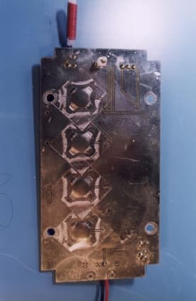
Click to zoom
Application Details
- Equipment Class
- DSC - Part 15 Security/Remote Control Transmitter
- Date of Grant
- Apr 10, 2000
- Application Purpose
- Original Equipment
- Date of Application
- Feb 09, 2000
- Frequency Range
- 418.00000000 - 418.00000000
- Company
- Base Engineering Inc.
- Country
- Canada
Documents & Files
Document Text
Text extracted from the exhibit documents filed with the FCC. Open a document above to read the original.
Users Manual
BASE ENGINEERING INSTALLATION & OPERATION RADIO REMOTE CONTROL SYSTEM ProControl Model RVC400 FCC ID: N8K-4401B THIS DEVICE COMPLIES WITH PART 15 OF THE FCC RULES. OPERATION IS SUBJECT TO THE FOLLOWING CONDITIONS:(1) THIS DEVICE MAY NOT CAUSE HARMFUL INTERFERENCE AND (2) THIS DEVICE MUST ACCEPT ANY INTERFERENCE THAT MAY CAUSE UNDESIRED OPERATION. DRAFT COPY READ THIS FIRST We all know how painful it is to read equipment manuals. In the interest of satisfying the novelty of “hooking it up and trying it out” without going through the entire manual first, we have provided a short “minimal” connection system to try it out; 1) Connect a 12 volt power supply to the receiver at the power supply pigtail-see picture for what connection is a +12V and what is Gnd. Be sure it’s correct before you turn the power on! 2) Hook nothing else up to the receiver. 3) Turn the 12V power on – the led indicator beside the setup button should blink once then go out. 4) Press the set-up button 5 times in a row – not too fast – about 2 times a second. The led should blink 5 times and go out. 5) Take the transmitter and press any button on it – the corresponding led beside the relay channel on the circuit board should light up – the relays are the little white blocks on the circuit board – the red indicator LED’s are close to each of them. THAT’S IT! – You have just taught the receiver to work with the transmitter and can operate the channels in momentary mode. There’s a lot more you can do but ... you guessed it ... you will have to read the manual. Thanks very much for purchasing this BASE Engineering remote control system. Setting Operation Mode for Each Channel Each channel of the receiver can be programmed to operate in one of four modes; 1) Momentary 2) Latched 3) Emergency Latched 4) Safety Timer Momentary Momentary The output channel on the receiver is activated ONLY when the corresponding transmitter button is depressed. This operation is similar to a momentary push-button; push to activate, release to de-activate. Latched The output channel on the receiver is changed from deactivated to activated when the corresponding button is pressed on the transmitter. Once the transmitter button is released, the channel remains activated on the receiver. Pressing the button a second time and releasing it on the transmitter causes the receiver channel to change from activated to de-activated. This operation is similar to a push-on, push off switch. Push once to activate, push again to deactivate. Emergency Latched The output channel on the receiver is changed from deactivated to activated when the corresponding button on the transmitter is pressed. Pressing the button on the transmitter and releasing it further will have no effect – the channel on the receiver will remain activated. The only way to deactivate the channel on the receiver is to press the reset button on the RECEIVER unit. This operation is similar to a kill button on a piece of machinery – once the button is pressed the machine will be immediately stopped, but releasing and pressing the button again has no effect. Safety Timer Momentary The output channel on the receiver operates identically as the momentary operation with one exception – if the transmitter button is pressed continuously for longer than 30 seconds, the receiver unit will automatically deactivate the channel. To activate the channel for longer than 30 seconds, the button on the transmitter must be momentarily released and then re-pressed again at least once every 30 seconds. This operation is commonly used for a “smart dead-man” operation. It allows the unit to be used as a dead-man switch but with the added feature that a bypassed switch (i.e. button permanently forced closed) will not allow the system to operate indefinitely. Programming Each Channel’s Operation Mode Each channel can be individually set to operate in one of the four modes described earlier. The programming operation involves removing the cover on the receiver unit and pressing a set-up button on the internal circuit board several times while watching the red led indicator. Steps to program each channel; 1) Turn power off to the receiver unit. 2) Remove the cover of the receiver unit and locate the set-up push button on the internal circuit board as well as the indicator led beside it. This button is used to program all internal settings in the receiver. 3) Turn power on to the receiver unit – watch that the indicator led blinks once – this indicates that the receiver is functioning properly. Once you have started the programming operation if you lose track of your place in the sequence, turn the power off and then on again to start the operation over. 4) Press the set-up button 10 times in a row – not too slow – about 2 times a second. Once the button has been pressed 10 times in a row – watch the led indicator. It should blink 10 times, repeat the 10 presses again. 5) Once the led has blinked 10 times, the receiver unit is now waiting for the channel number. Press the button the number of times corresponding to the channel you wish to set. For example, one press for channel 1, two presses for channel 2. 6) The led will blink the number of times to verify that you have selected the correct channel. If you have not selected the proper channel or lose track of how many times you have pressed the button, turn the power off and then on again and start from the first step above. 7) Now that the channel has been selected, the operating mode for this channel will be set. Press the button the number of times below for the mode of operation desired for the channel – see elsewhere in the manual for a description of these modes of operation; 1 Press-Channel will be momentary operation 2 Presses-Channel will be latched operation 3 Presses-Channel will be emergency latched operation 4 Presses-Channel will be momentary with 30’s safety timer 8) The led will blink the number of times you have pressed the button and then will go out. …
Text truncated - open the document above for the full version.
Block Diagram
BASE Engineering Page 1 of 14 RVC 400T FCC Certification Application FCC ID# N8K-4401B RVC400T Transmitter Circuit Description Keypad Four momentary buttons are constructed with contacts on the circuit board (etched as part of the traces on the board) and metal snap dome components affixed with tape. Pressing a rubber pushbutton on the front panel of the hand-held transmitter pushes an integral rubber plunger that in turn presses the metal dome and causes the contacts to close. These domes are specified for several million operations before failure and only make contact while the operator is holding pressure on the front panel rubber pushbutton. They can not be “latched” down and therefore ensure only momentary operation. Code Generator Chip The code generator integrated circuit is connected to the four keypad switches as outlined above, as well as a 4MHz resonator, a led indicator, a low battery detection circuit, and an RF transmitter module. As long as a button is being held down, the code generator applies power to the transmitter module and emits the control code for the button to the RF transmitter module. Low Battery Detection Circuit This circuit generates a logic signal that is used to feed to the generator chip. When the battery is low, the open collector output of the detection circuit is pulled low, and this low signal is used by the code generator chip to determine when to flash the led. RF Transmitter Module An “Off the shelf” complete turn-key module (p/n TXM-418-F) requiring power, input signal, and antenna connections is utilized. Please see the attached data sheet provided by Radiometrix. T-Pad Attenuation Circuit A 3 resistor circuit is used to provide a matched attenuator between the RF output of the transmitter module and the antenna. During certification testing it was found that this attenuator is not needed and this 3 resistor network is strapped with 0 ohm resistors enabling a “straight through” connection from the output of the transmitter module to the antenna. Antenna & Ground System A helically wound antenna is utilized which consists of 26 turns of .020” diameter wire on a 0.125” diameter nylon form. It is installed in a small grommet protruding from the end of the enclosure and then soldered directly to the circuit board. This is a permanently installed antenna and is not replaceable by the end user. The unit must be sent back to the factory for repair or replacement if broken. BASE Engineering Page 2 of 14 Block Diagram The attached block diagram details all circuit functions introduced above and also shows all of the oscillators in RVC400T device. Schematic Diagram The attached schematic diagram details all circuit components and interconnections. NOTE ON TRANSMISSION OF BUTTON CODES The RF Transmitter Module used in this transmitter is an off the shelf product produced in England. The manufacturer’s data sheets and technical information have been included as part of this information package. Much of the data sheets and literature from this manufacturer, refer to the transmission of “data” and “serial data streams” using this device. BASE AVIATION IS NOT TRANSMITTING DATA OR SERIAL INFORMATION WITH THIS MODULE - CONTROL CODES ONLY ARE BEING TRANSMITTED to signal the receiver that the hand-held transmitter’s momentary push buttons are being pressed. Page 3 of 14 SHEET 1 o f 1 Drawn By:Stephan Beyea Date:September 14/99Title: RVC 400T - Four Button Transmitter Block Diagram Rev: 0 BASE Aviation Ltd. FCC Grantee Code – N8K KeypadButtons LED Indicato r POWER SUPPLY CIRCUIT LOW BATTERY DETECTION CIRCUIT CODE GENERATOR POWER CODE RF TRANSMITTER MODULE Antenna T-Pad Attenuato r 9 Volt Battery Page 4 of 14 Page 5 of 14 Page 6 of 14 Page 7 of 14 Page 8 of 14 Page 9 of 14 Page 10 of 14 Page 11 of 14 Page 12 of 14 Page 13 of 14 Page 14 of 14
Cover Letter(s)
RVC 400T FCC Certification Application FCC ID# N8K-4401B FCC EA# EA96746 LIST OF ATTACHMENTS No.DescriptionFile NameFile Type 1Proposed FCC ID LabelFCC Label.docWord 97 2RVC 400T External and Internal Photos.RVC400T Photos.docWord 97 3RVC400T Transmitter Circuit Description (including block diagram and schematics). RVC400T Description.docWord 97 4MPB Technologies Inc. Test Report ( including test set-up photos). MPB Report.exeWord 97 (self extracting ZIP) 5RVC 400T Installation and Operation ManualRVC400 FCC Manual.docWord 97
Cover Letter(s)
Re: FCC ID N8K4401B Applicant: BASE Engineering Ltd. Correspondence Ref. Number: 12392 731 Confirmation Number: EA96746 March 2, 2000 Dear Mr. Dichoso: I have resubmitted the MPB Technologies test report for our product that we are requesting FCC approvals. The original submission was done on Feb 21 but perhaps transmission errors prevented it from arriving at your site. It is titled “MPB Report A.doc” and is a Word 97 document. The submission has been done through the OET electronic submission on the Internet web page. Sincerely Mark G. Sanford Base Engineerin g Ltd. Cc Sean Darrah
External Photos
BASE ENGINEERING Page 1 of 6 RVC 400T FCC Certification Application FCC ID# N8K-4401B RVC400T Transmitter Photos RVC400T Front View BASE ENGINEERING Page 2 of 6 RVC 400T Rear View BASE ENGINEERING Page 3 of 6 RVC 400T Internal View Keypad BASE ENGINEERING Page 4 of 6 RVC 400T Internal View Circuitry Antenna RF Transmitter Module 9V Battery Connection Code Generator BASE ENGINEERING Page 5 of 6 RVC 400T Internal View Installed Circuitry BASE ENGINEERING Page 6 of 6 RVC 400T Internal View Enclosure Lid Removed
ID Label/Location Info
Page 1 of 1 RVC400T Transmitter Proposed FCC Label RVC 400T FCC Certification Application FCC ID# N8K-4401B Transmitter Enclosure Bottom View (Not to Scale) Adhesive backed foil label Overall dimensions 1.5” x 3” MANUFACTURED BY BASE BASEBASE BASE ENGINEERING 1714 Rothesay Rd., Saint John, NB, E2H 2J4 1-800-924-1010 DATESERIAL # MODEL # FCC ID# N8K-4401B
ID Label/Location Info
Page 1 of 1 RVC400T Transmitter Proposed FCC Label Revised Feb 21, 2000 RVC 400T FCC Certification Application FCC ID# N8K4401B EA# EA96746 Transmitter Enclosure Bottom View (Not to Scale) Adhesive backed foil label Overall dimensions 1.5” x 3” MANUFACTURED BY BASE BASEBASE BASE ENGINEERING 1714 Rothesay Rd., Saint John, NB, E2H 2J4 1-800-924-1010 DATESERIAL # MODEL # FCC ID: N8K4401B
Contact Information
Applicant
Christina Desjardins(Production Engineering Manager)
Technical Contact
C-Tek ControlsLewis H Cobb
[email protected](506) 451-2142
Incutech Center · Fredericton, New Brunswick · Canada
Non-Technical Contact
Base Aviation Ltd.Sean B Darrah
[email protected](506) 847-2273
Test Firm
MPB Technologies Inc.Daniele Zanette
Technical Specifications
| # | Rule Parts | Frequency Range | Power Output | Tolerance |
|---|---|---|---|---|
| 1 | 15C | 418 MHz - 418 MHz | - | Hz |
Other Applications from Base Engineering Inc.
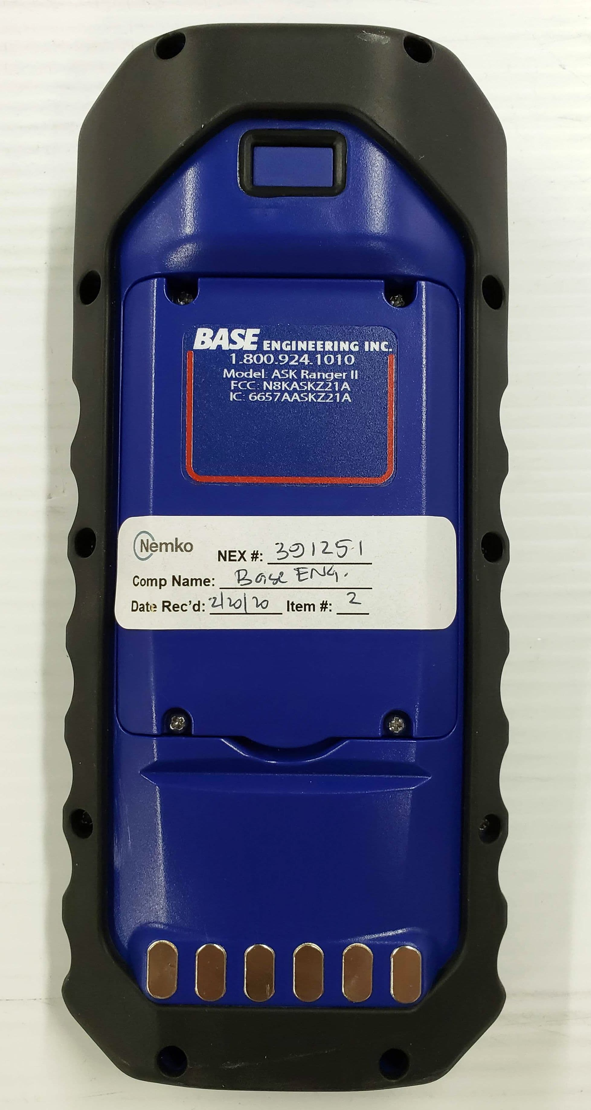
N8KASKZ21A
Feb 18, 2021HANDHELD DEVICE
Equipment Class
DSC - Part 15 Security/Remote Control Transmitter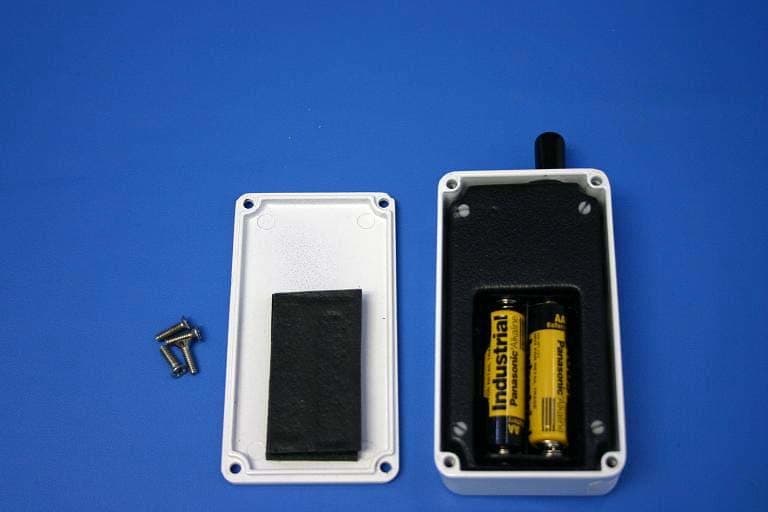
N8KJ8T6J11
Oct 18, 2006The Base Engineering ASK Remote
Equipment Class
DSC - Part 15 Security/Remote Control Transmitter