N8TSOV333ATS3-A/B Transmitter
Sovereign Tracking Systems, L.L.C.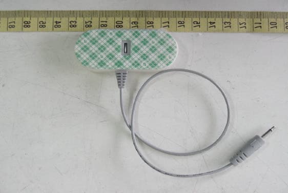
Click to zoom
Application Details
- Equipment Class
- DSC - Part 15 Security/Remote Control Transmitter
- Date of Grant
- Mar 08, 2004
- Application Purpose
- Original Equipment
- Date of Application
- Mar 08, 2004
- Equipment Note
- ATS3-A/B Transmitter
- Frequency Range
- 418.00000000 - 418.00000000
- Country
- United States
Documents & Files
Document Text
Text extracted from the exhibit documents filed with the FCC. Open a document above to read the original.
Users Manual
Sovereign Tracking Systems L.L.C. 1108 Industrial Pkwy, Brick New Jersey 08724 (732) 836-3400 FAX (732) 836-9899 URL http://www.sovtechcorp.com ® Tracking Systems L.L.C. PalTrack ATS3-A/B Operational Manual Asset Tracking System III (A/B) The ATS3 designed by Sovereign Tracking System LLC. provides a very affordable and accurate tracking system for locating and position asset and product within localized facilities. The attachment of the ATS3 unit to an asset or product is performed in the following steps: 1. Open the packaging and remove the ATS3 transmitter. 2. Attach the ATS3 to an asset or product by orienting the transmitter assembly to the asset or product so that the adhesive side of the transmitter is facing towards object. 3. Remove the protective adhesive paper from the ATS3 transmitter. 4. Orient the ATS3 to the desired location on the asset or product, and press the ATS3 FIRMLY to the asset or product. 5. DO NOT TRY TO RELOCATE OR REMOVE THE ATS3 FROM THE ATTACHED ITEM. 6. IF THE ATS3 IS REMOVED FROM THE Asset, it will be set to alarm mode. 7. Once the ATS3 is secured to and asset or product, verify operation of the system by moving the ATS3 transmitter either up or down, or side to side, and verify the data on the computer. For details on computer operation, reference PalTrack installation manual. PalTrack ATS3-A/B Transmitter ATS3-A/B unit Installation and Operational Instructions Adhesive side Activation Pin ATS3-B Shown Sovereign Tracking Systems L.L.C. 1108 Industrial Pkwy, Brick New Jersey 08724 (732) 836-3400 FAX (732) 836-9899 URL http://www.sovtechcorp.com ® Tracking Systems L.L.C. ATS3-A Configuration: The ATS3-A is the base configuration transmitter with out data input capability. This configuration provides normal operation under motion and emergency transmit notification when the transmitter is removed form an asset or object once affixed and activated. ATS3-B Configuration: The ATS3-B provides a configuration whereby external data input can be detected from an asset or object. This data input feature allows for a transistor to transistor (TTL) logic input e.g. “0” or “1”. The logic input voltage is either zero “0” Vdc for logic “0” or a maximum of 5.5Vdc for a logic “1”. The status of this logic is transmitter as a status bit during normal or emergence transmit modes. The data input in accomplished through the use of a “Mini Phone” plug. The outer shell of the mini phone plug is ground with the center tip at a positive potential of no more than 5.5Vdc. For details on computer operation, reference PalTrack installation manual. Notice: The changes or modifications not expressly by the party responsible for compliance could void the user’s authority to operate the equipment. Model: ATS3-(A/B) FCC ID: N8TSOV333 THIS DEVICE COMPLIES WITH PART I5 OF THE FCC RULES. OPERATION IS SUBJECT TO THE FOLLOWING TWO CONDITIONS: (1) THIS DEVICE MAY NOT CAUSE HARMFUL INTERFERENCE AND (2) THIS DEVICE MUST ACCEPT ANY INTERFERENCE RECEIVED, INCLUDING INTERFERENCE THAT MAY CAUSE UNDESIRED OPERATION. MADE IN TAIWAN
Cover Letter(s)
1 Mike Kuo From: S. S. Liou Sent: March052004Friday 12:33 AM To: Mike Kuo Cc: R00/; R00/ Subject: Re: SOVEREIGN TRACKING SYSTEMS L.L.C., FCC ID:N8TSOV333, AN04T3664 Exhibit-D-ID_Label_ revised.pdf... Revised Operational Descriptio... Dear Mike, Ans. #1: This device will be attached to the asset or product to be monitored. Please refer to page 1 of user manual for installation instructions. Ans. #2: Please refer to revised label format. Ans. #3: This device is a portion of the tracking system which is designed for security / remote monitoring of asset and product. After been attached to the tracked object, this transmitter is in the standby mode. When the object is moved, it will transmit signals to the system. If this device is separated from the object, it will transmit emergency code to the system. The mini-phone plug is designed for detecting data input from object. Zero Vdc stand for "0" and 5.5(max) Vdc stand for "1". By detecting the change from "0" to "1" or from "1" to "0", it transmits signal to the system. This function has various applications depending on system definition. The signal pulse train of each condition is described in the revised operational description. Ans. #4: Please refer to revised operational description. Best regards, ================================ S. S. Liou Engineer / EMC Dep. II ETC ----- Original Message ----- From: "Mike Kuo" <[email protected]> To: "ETC/Iris (E-mail)"; "Liou, S. S. (E-mail)" Cc: "Will Yauo (E-mail)" < Sent: Thursday, March 04, 2004 10:55 AM Subject: FW: SOVEREIGN TRACKING SYSTEMS L.L.C., FCC ID:N8TSOV333, AN04T3664 > > > -----Original Message----- > From: CERTADM > Sent: Wednesday, March 03, 2004 6:54 PM > To: Mike Kuo > Subject: SOVEREIGN TRACKING SYSTEMS L.L.C., FCC ID:N8TSOV333, AN04T3664 > > > Notice_content > ------------- > Question #1: Please provide PalTrack installation manual as mentioned in the > user manual and operational description. > 2 > Question #2: FCC ID number can not be read. Please provide a clear copy of > FCC ID label format. > > Question #3: The function of this device can not be understood. In the > operational description or in the user manual, there is no information > provided to indicate that this device complies with periodical transmitter > per 15.231 definition. What is the device will be connected via " > mini-phone " jack? > > Question #4: The operational description is same as the information contain > in the user manual. Please provide a clear technical description in the > operational description to justify periodical transmitter and how the device > will be activated ? > > Best Regards > > > Mike Kuo > The items indicated above must be submitted before processing can continue > on the above referenced application. Failure to provide the requested > information within 30 days of the original e-mail date may result in > application dismissal and forfeiture of the filing fee. Also, please note > that partial responses increase processing time and should not be submitted. > Any questions about the content of this correspondence should be directed to > the e-mail address listed below the name of the sender.
External Photos
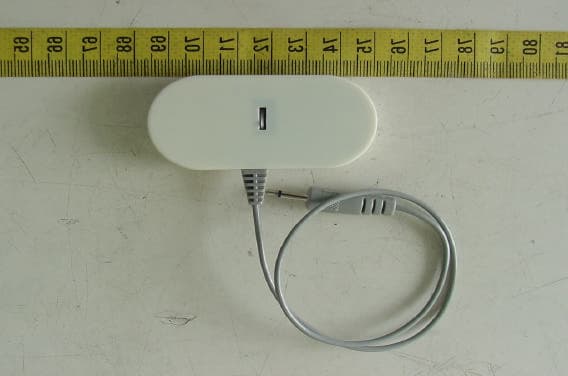
ETC Report No.:ET93R-01-053 FCC ID.: N8TSOV333 Rev. No 1.0 CONSTRUCTED PHOTOS of EUT Top View of EUT Rear View of EUT
Internal Photos
ETC Report No.:ET93R-01-053 FCC ID.: N8TSOV333 Rev. No 1.0 CONSTRUCTED PHOTOS of EUT Internal View of EUT Component View of Main PCB ETC Report No.:ET93R-01-053 FCC ID.: N8TSOV333 Rev. No 1.0 CONSTRUCTED PHOTOS of EUT Solder View of Main PCB
Operational Description
Operational Description This device is the transmitter portion of the tracking system which is designed for security / remote monitoring of asset and product. By receiving the signal from the transmitter, this system can monitor the tracking object. The condition that will activate this transmitter is described as following: 1. Power on. When the battery is put on this transmitter, an one second no modulation signal and then a 6 codes (70ms * 6 = 420 ms) signal will be transmitted once for checking the system. 2. Start up. When the switch on the back (adhesive side) of the transmitter is pressed more than 5 seconds, a 6 codes (70ms * 6 = 420 ms) signal will be transmitted once. 3. Vibrated or moved. When the tracking object is moved, the transmitter attached to the object is also moved. This action will activate the transmitter. A 3 codes (70ms * 3 = 210 ms) signal will be transmitted. If the motion continues, the transmitter will continue to send the 3 codes signal with a time interval of 10 seconds. In this condition the transmitting time is 210 ms and the silent period is 10 seconds which is longer than 210 ms * 30 = 6.3 s. So it complies with the requirement of section 15.231(e) of FCC rules. 4. Standby mode. After the transmitter is started up, it is in standby mode. In standby mode the 3 codes (70ms * 3 = 210 ms) signal will be transmitted in every 15 minutes. This also complies with the requirement of section 15.231(e) of FCC rules. 5. Emergency mode. When the switch is off (usually when the transmitter is separated from the attached object) the 3 codes (70ms * 3 = 210 ms) signal with a time interval of 10 seconds will be transmitted 5 times. Then this transmitter will not transmit until been started up again. Following the calculation above, this also complies with the requirement of section 15.231(e) of FCC rules. 6. External activation. When the voltage change (5.5 Vdc to 0 Vdc) is detected from the “mini-phone” plug, a 3 codes signal is transmitted. Frame 1 : 70mSFrame 2 : 70mS PilotAddressData 70 x 3 = 210mS 210mS10 Sec Frame 3 : 70mS IMTS/ATS Normal Transmission Code Format
Test Report
Rev. No 1.0 FCC Part 15 EMI TEST REPORT of E.U.T. : ATS3-A/B Transmitter FCC ID. : N8TSOV333 MODEL : ATS3-A/B Working Frequency : 418 MHz for APPLICANT : Sovereign Tracking Systems L.L.C. ADDRESS :1108 Industrial Pkwy, Brick New Jersey 08724 U.S.A.. Test Performed by ELECTRONICS TESTING CENTER, TAIWAN NO. 34, LIN 5, DING FU TSUN, LINKOU HSIANG TAIPEI HSIEN, TAIWAN, R.O.C. Tel : (02)26023052 Fax : (02)26010910 http://www.etc.org.tw ; e-mail: [email protected] Report Number : ET93R-01-053 ETC Report No.:ET93R-01-053 FCC ID.: N8TSOV333 Rev. No 1.0 TEST REPORT CERTIFICATION Applicant : Sovereign Tracking Systems L.L.C. 1108 Industrial Pkwy, Brick New Jersey 08724 U.S.A.. Manufacturer : Mingtek Electronics Inc. 8F-5, No.81, Hsin Tai Wu Rd, sec1, His-Chih City, Taipei 221, Taiwan, R.O.C. Description of EUT : a) Type of EUT : ATS3-A/B Transmitter b) Trade Name : Soverigan c) Model No. : ATS3-A/B d) FCC ID : N8TSOV333 e) Working Frequency : 418MHz f) Power Supply : DC 3V Battery Regulation Applied : FCC Rules and Regulations Part 15 Subpart C (2002) I HEREBY CERTIFY THAT; The data shown in this report were made in accordance with the procedures given in ANSI C63.4 and the energy emitted by the device was founded to be within the limits applicable. I assume full responsibility for accuracy and completeness of these data. Note : 1. The results of the testing report relate only to the items tested. 2. The testing report shall not be reproduced except in full, without the written approval of ETC. Issued Date : Feb. 09, 2004 Test Engineer : (Jiapeng Chen) Approve & Authorized Signer : Will Yauo, Manager EMC Dept. II of ELECTRONICS TESTING CENTER, TAIWAN ETC Report No.:ET93R-01-053 FCC ID.: N8TSOV333 Rev. No 1.0 Table of Contents Page 1. GENERAL INFORMATION.....................................................................................................................................................1 1.1 PRODUCT DESCRIPTION...........................................................................................................................................................1 1.2 CHARACTERISTICS OF DEVICE:...............................................................................................................................................1 1.3 TEST METHODOLOGY..............................................................................................................................................................1 1.4 TEST FACILITY..........................................................................................................................................................................1 2. DEFINITION AND LIMITS.......................................................................................................................................................2 2.1 DEFINITION................................................................................................................................................................................2 2.2 RESTRICTED BANDS OF OPERATION.....................................................................................................................................2 2.3 LIMITATION...............................................................................................................................................................................2 2.4 LABELING REQUIREMENT.......................................................................................................................................................4 2.5 USER INFORMATION.................................................................................................................................................................4 3 SYSTEM TEST CONFIGURATION.........................................................................................................................................5 3.1 JUSTIFICATION..........................................................................................................................................................................5 3.2 DEVICES FOR TESTED SYSTEM...............................................................................................................................................5 4. RADIATED EMISSION MEASUREMENT.............................................................................................................................6 4.1 APPLICABLE STANDARD.........................................................................................................................................................6 4.2 MEASUREMENT PROCEDURE..................................................................................................................................................6 4.3 TEST DATA.................................................................................................................................................................................8 4.4 FIELD STRENGTH CALCULATION..........................................................................................................................................9 4.5 ACTIVATE TIME........................................................................................................................................................................9 4.6 CALCULATION OF DUTY FACTOR.........................................................................................................................................9 4.8 MEASURING INSTRUMENT SETUP.......................................................................................................................................15 4.9 RADIATED MEASUREMENT PHOTOS...................................................................................................................................16 5. BANDWIDTH OF EMISSION...............................................................................................................................................17 5.1…
Text truncated - open the document above for the full version.
Test Setup Photos
ETC Report No.:ET93R-01-053 FCC ID.: N8TSOV333 Rev. No 1.0 Radiated Measurement Photos
Contact Information
Applicant
William A. Robinson(President and Chief Executive Officer)
732-223-9798Fax: 732-223-7925
Test Firm
Electronics Testing Center, TaiwanWin-Po Tsai
Technical Specifications
| # | Rule Parts | Frequency Range | Power Output |
|---|---|---|---|
| 1 | 15.231(e) | 418 MHz - 418 MHz | - |
Other Applications from Sovereign Tracking Systems, L.L.C.
N8TSOV333B
Jul 01, 2004ATS3-A/B Transmitter
Equipment Class
DSC - Part 15 Security/Remote Control Transmitter
N8TSOV230
May 21, 2001Asset Tracking Transmitter
Equipment Class
DSC - Part 15 Security/Remote Control Transmitter
N8TSOV222
May 20, 1999DSC - Part 15 Security/Remote Control Transmitter
Equipment Class
DSC - Part 15 Security/Remote Control Transmitter