NB31032Highway Safety Transmitter
Highway Technologies Inc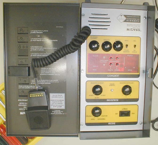
Click to zoom
Application Details
- Equipment Class
- TNB - Licensed Non-Broadcast Station Transmitter
- Date of Grant
- Jul 22, 2002
- Application Purpose
- Original Equipment
- Date of Application
- Jan 14, 2002
- Equipment Note
- Highway Safety Transmitter
- Frequency Range
- 26.96500000 - 27.40500000
- Company
- Highway Technologies Inc
- Country
- United States
Documents & Files
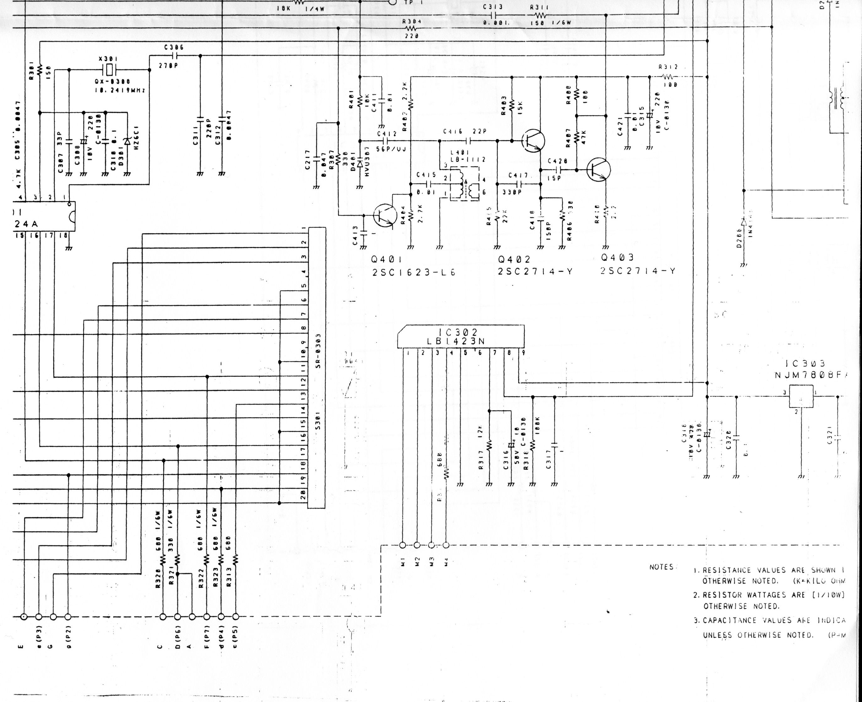
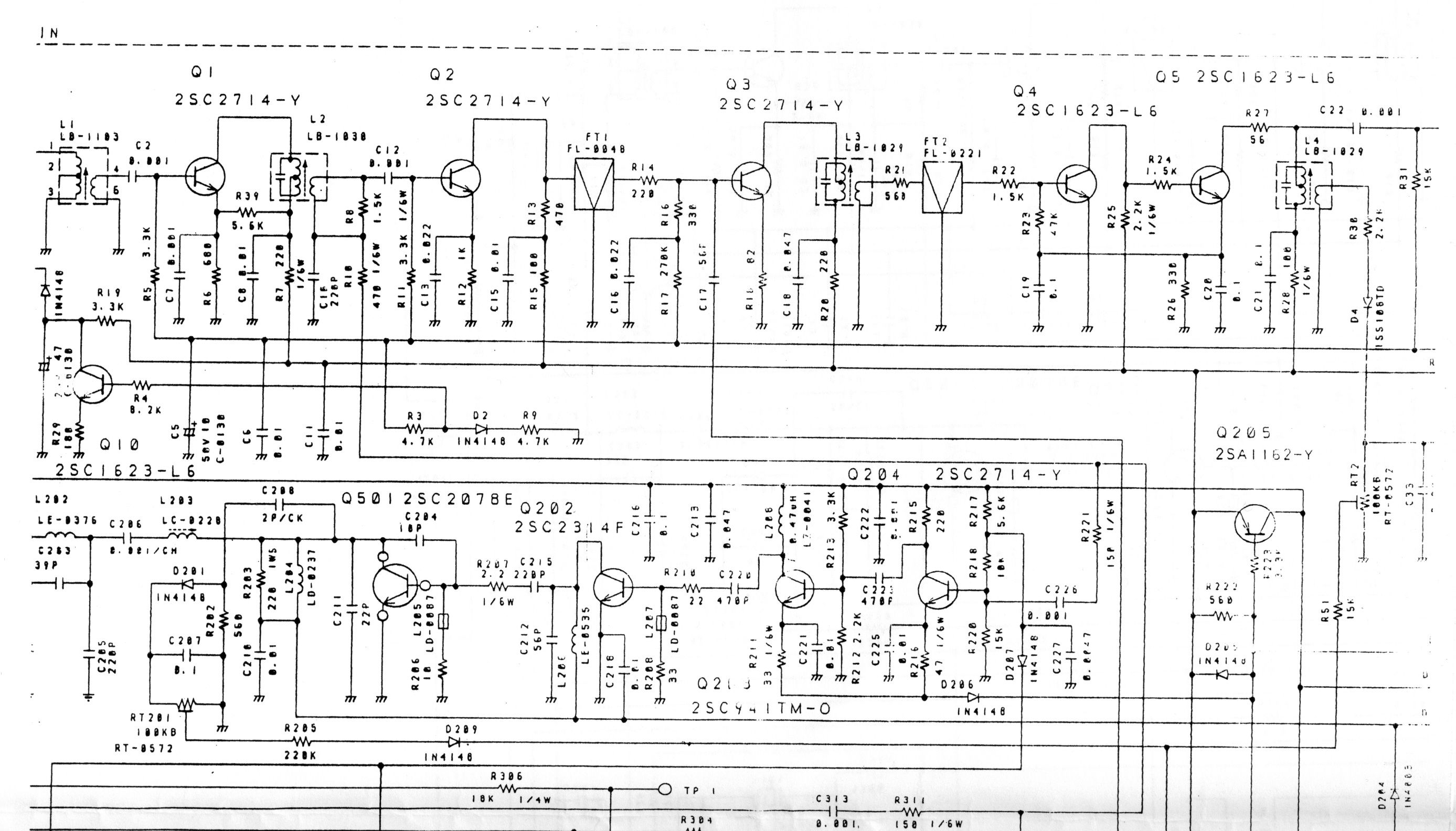
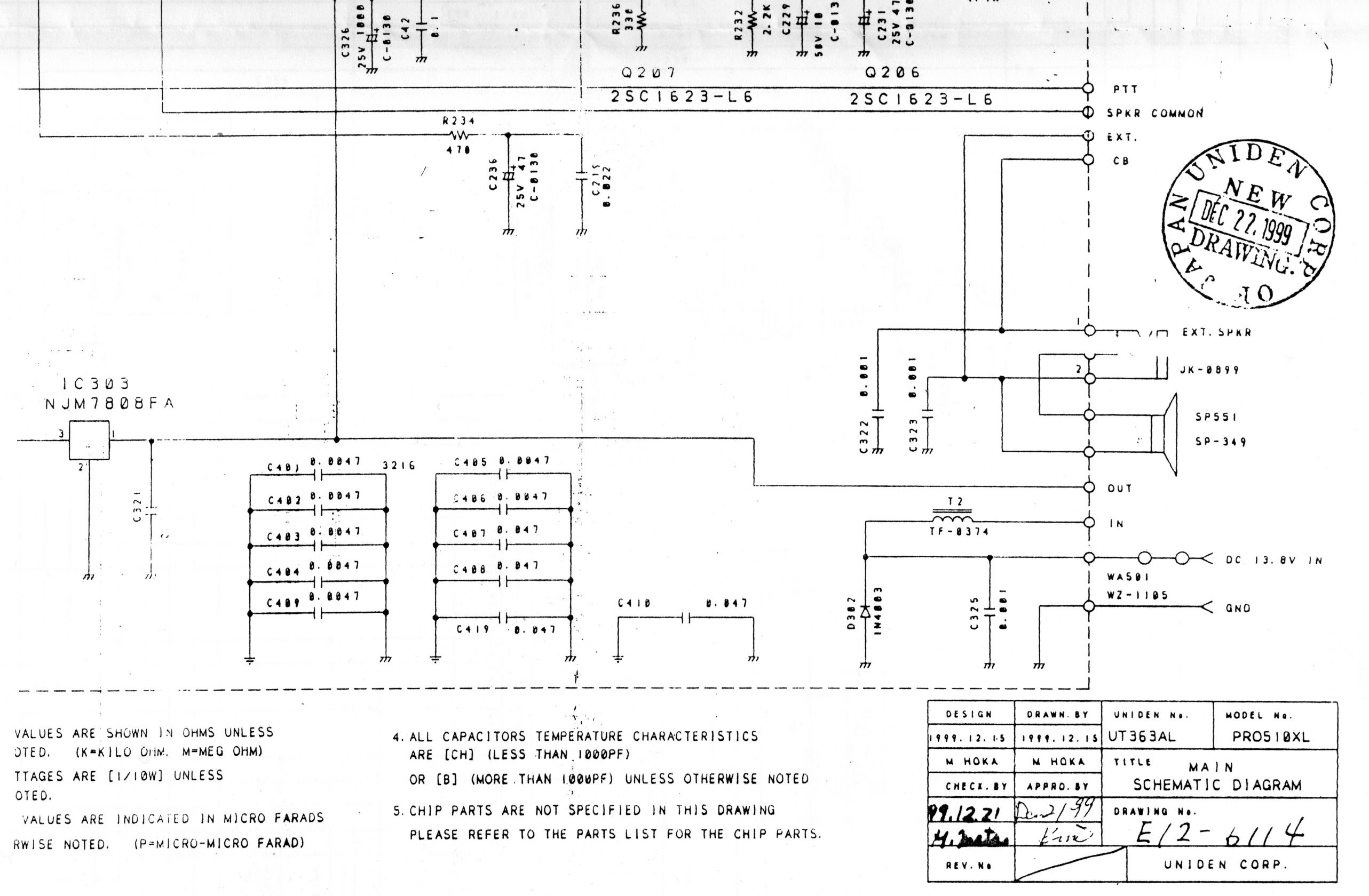
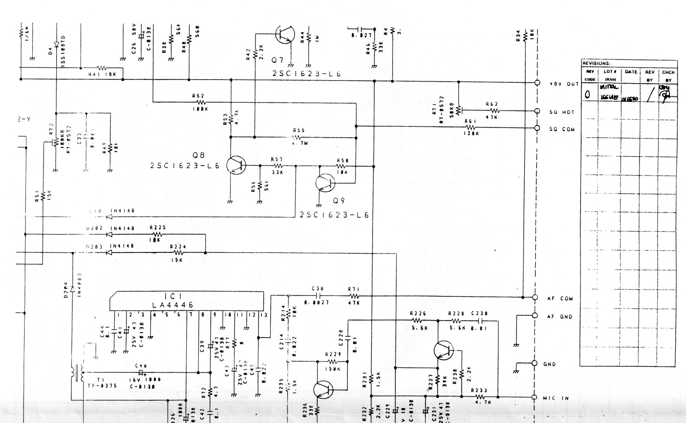
Document Text
Text extracted from the exhibit documents filed with the FCC. Open a document above to read the original.
Users Manual
THE W IZARD Work Zone Alert and Information Radio THE W IZARD ® Wizard Field Operation Procedures A guide for settings and message selection under varying operating conditions. Highway Technologies, Inc 81 Texaco Road • Mechanicsburg, PA 17050 • 717-691-8007 Highway Technologies, Inc 81 Texaco Road • Mechanicsburg, PA 17050 • 717-691-8007 RF Safety Warning The antenna for this device must be mounted on top of the roof of the vehicle or on top of the construction site trailer away from nearby personnel. All personnel must remain at least 7” from an unobstructed antenna to avoid extended peri- ods of RF exposure. With trucks logging more than 50 billion vehicle miles on the nation's roads, more maintenance and more work zones increases the opportunity for more accidents. Higher speeds, inattentive driving and closer spacing contribute to rear-end vehicle collisions and hazardous conditions for road construction workers. The Wizard® is designed to provide advanced warning of impending traffic slowdowns to give all vehicles, especially heavy trucks, the necessary time to stop. The Wizard is a completely portable wireless broadcasting system adaptable to any work site, sending localized messages on selected CB channels. The Wizard counts down the selected interval for sending, listens for a break in activity on channels 9 and 19 (or other user selected and emergency CB chan- nels), and broadcasts when clear. Care is taken to not interfere with normal CB communication between vehicles. A short message alerts the driver to slow down. The message can be broad- cast on a second user selected channel if desired. Messages can be changed at the site, broadcast distances adjusted for traffic backup, and message frequency modified to compensate for average speeds. WARNING The Citizens Band (CB) Radio Service is under the jurisdiction of the Federal Communications Commission (FCC). Any adjustments or alterations which alter the performance of the transceiver's original FCC type acceptance, or change the frequency determining method, are strictly prohibited. Replacement or substitution of crystals, transistors, ICs, regulator diodes, or any other part of a unique nature, with parts other than those recommended by Highway Technologies, Inc., may cause violation of the technical regulations of Part 95 of the FCC rules or violation of type acceptance require- ments of Part 2 of the rules. This radio has been type accepted and certified by the FCC. Page 2 Select desired Transmit Channel using the “Channel Selector” switch Adjust Squelch and Volume Controls to desired levels Listen for “break” in conversations Squeeze (and hold) microphone switch while speaking. As soon as you finish your message release the micro- phone switch and listen for a response. Be sure to hold the microphone near your mouth so that your voice - not just background noise - can be heard. Release microphone switch to listen for response Enclosure General Specifications The Wizard enclosure is a protected, weather resistant box. Boxes that are fully weather protected are available as an option. Internal components are securely mounted to the case and inter - connected with industrial connectors It may be used in many weather conditions so long as no part of the box is submerged. Care should be taken to protect the unit with appropriate security measures if placed in an unattended location. Page 11 Set The Wizard to Broadcast Automatically Set “MODE” switch to “TRANSMIT” position. Remote Antenna Installation Construction Site Trailer If unit is used inside a trailer, external antenna (optional) may be mounted in any convenient outside location accord - ing to instructions Plug lead-in shielded cable to “antenna in” connector. Operate the system according to all previous instructions. No personnel should be closer to the antenna than 7 unob - structed inches. NOTE: DO NOT OPERATE WITHOUT A PROPERLY CONNECTED AND LOCATED ANTENNA ! Power Panel Indicators There are two light bar indicators that provide dynamic strength infor - mation Meters The “VOLTS” bar indicates the level of DC power being provided to the unit. It should read about 12V for proper operation . The “ACTIVITY” bar gives an indication of how frequent and strong the signals are that are being received by the CB. Distant transmissions (weak signals) will not cause the system to interpret the channel as being busy. CB Microphone Operation Operator Communication The “Microphone” may be used if desired for live communications Rotate “MODE” switch to “STD CB” Page 10Page 3 Elimination of licensing .............................................4 Rules You Should Know .............................................4 Easy to Operate ......................................................5 Operation ...............................................................6 If the Transceiver is placed Indoors...........................6 If the Transceiver is placed Outdoors ........................6 Select power source .............................................6 12 volt operation .............................................6 Initial Set-up.........................................................6 Message Set-up ...................................................7 To Record A Message ....................................7 To Listen and Confirm Recorded Message(s).........7 Transmit Set-up ...................................................7 CB Channel Selection .......................................8 To Designate Working Channels ........................8 CB Broadcast Message ....................................9 To Confirm Complete Setup ..............................9 Set The Wizard to Broadcast Automatically .........10 Remote Antenna Installation .................................10 Construction Site Trailer .................................10 Power Panel Indicators .......................................10 Meters .........................................................10 CB Microphone Opera…
Text truncated - open the document above for the full version.
Attestation Statements
Highway Technologies, Inc. • 81 Texaco Road, Mechanicsburg, PA 17050 • 717 691-8007 HARRISBURG, PENNSYLVANIA HIGHWAY TECHNOLOGIES, INC Mr. Joe Dichoso Federal Communications Commission 7435 Oakland Mills Road Columbia, MD 21046 Re: FCC ID NB31032 Applicant: Highway Technologies Inc Correspondence Reference Number: 23337 731 Confirmation Number: EA555689 Dear Mr. Dichoso, Most Wizards are placed in the front seat of a DOT cab. This could be for a snow plow, paint truck or crash truck. It is within 2 feet of the driver, who monitors the channel traffic to make sure the message is getting out. The antenna is placed on the roof of the vehicle with a magnetic mount. It can also be used in the front seat of a trooper car under similar circumstances. Our contemplation of remote operation was in response to PennDOT requests to be able to place a permanent roadside Wizard which could be activated by telephone for quicker response, especially during foul weather. The presumption was that having the Wizard listen electronically for busy conditions was equivalent to being under direct control. That model does not yet exist. If and when we wish to seek approval for such a device, we will request a suitable ruling. However, that issue does not apply to the current model. David C. Johnson Vice President Highway Technologies, Inc.
Cover Letter(s)
Highway Technologies, Inc. • 81 Texaco Road, Mechanicsburg, PA 17050 • 717 691-8007 HARRISBURG, PENNSYLVANIA HIGHWAY TECHNOLOGIES, INC December 6, 2001 Chief, Equipment Authorizations Branch Federal Communications Commission 7435 Oakland Mills Road Columbia, MD 21046 To Whom It May Concern: Please be advised that Highway Technologies, Inc. authorizes Washington Laboratories, Inc. to act on our behalf, until otherwise notified, for applications submitted to the Federal Communications Commission. We certify that we are not subject to denial of federal benefits, that includes FCC benefits, pursuant to Section 5301 of the Anti-Drug Abuse ACT of 1988, U.S.C. 862. Further, no party, as defined in 47 CFR 1.2002(b), to the application is subject to denial of federal benefits, that includes FCC benefits. Thank you for your attention to this matter. Sincerely, David C. Johnson David C. Johnson Vice President
Cover Letter(s)
To: Joe Dichoso [email protected] FCC Application Processing Branch Re: FCC ID NB31032 Applicant: Highway Technologies Inc Correspondence Reference Number: 23337 731 Confirmation Number: EA555689 Please respond to the items below by July 22, 2002 or the application will be dismissed per 2.917(a). 1) With regard to RF safety, please correct the following. The worst case time on/off is 20 seconds on with 30 second interval or 40%. MPE calculations used 60%. The antenna installation requirements in the MPE exhibit does not agree with the manual. The antennas and antenna locations in the MPE exhibit must agree with the manual. Please make the appropriate connections. If the calculated distance can be maintained with normal use and with appropriate RF safety warnings then no testing is required. If the distance cannot be maintained, testing is required. Provide the RF safety warning. The MPE exhibit has been revised per this request and has been uploaded as file “MPE Data Rev 1.pdf” 2) With regards to 95.402(c), your reply stated that there is no remote operation. This does not satisfy 95.402(c), someone has to be operating the device at all times. It appears that the device is meant to be left alone and operating standalone. The device will not be un-attended. The device will only be operated by personnel at all times during operation. A letter attesting to the usage of the unit has been uploaded, see exhibit “Attestation Letter.pdf”. Additionally, a revised manual has been uploaded under file name “Revised Wizard Manual.pdf”. Please note that the manual was provided to us in print galley format- the pages are out of numerical order. Thank you, Greg Snyder
External Photos
AR-103 Exterior Photos Side View, Fuse Holder, Connectors: Power and Antenna Side, Bottom View Door Open, Front Panel
ID Label/Location Info
FCC Label Model AR-103 FCC ID: NB31032 Highway Technologies, Inc. Made in USA Serial Number: XX X X X X ______________________________ This device complies with Part 15 of the FCC rules. Operation is subject to the following two conditions: 1. This device may not cause harmful interference, and 2. This device must accept any interference received, including interference that may cause undesired operation. Patented
Internal Photos
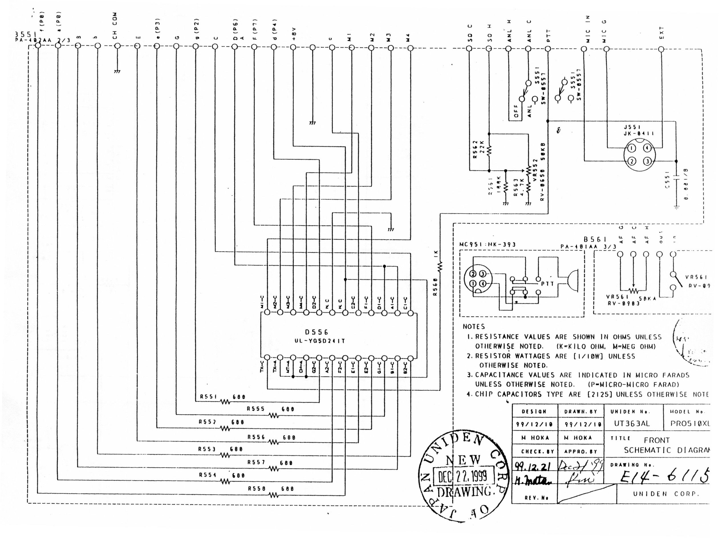
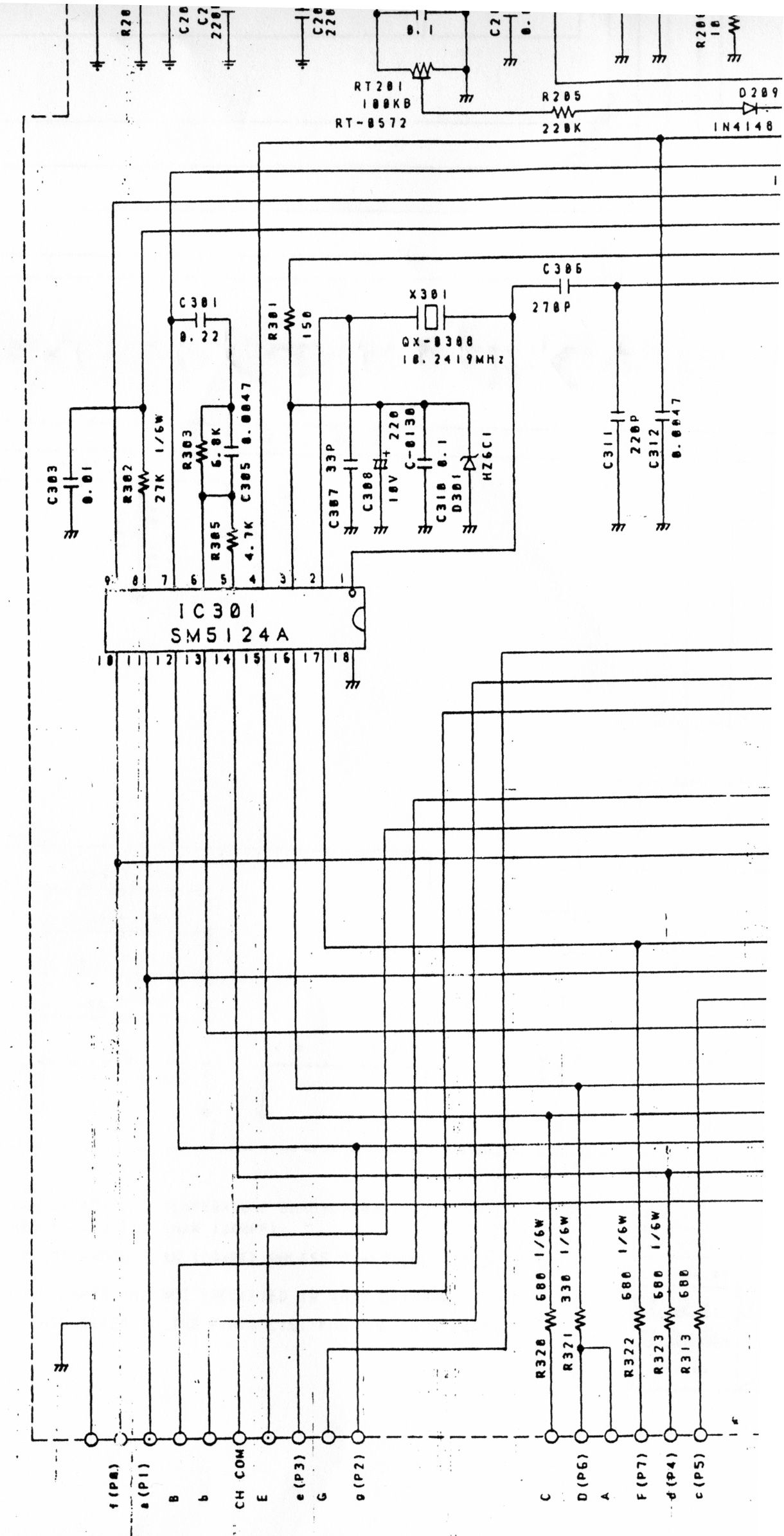
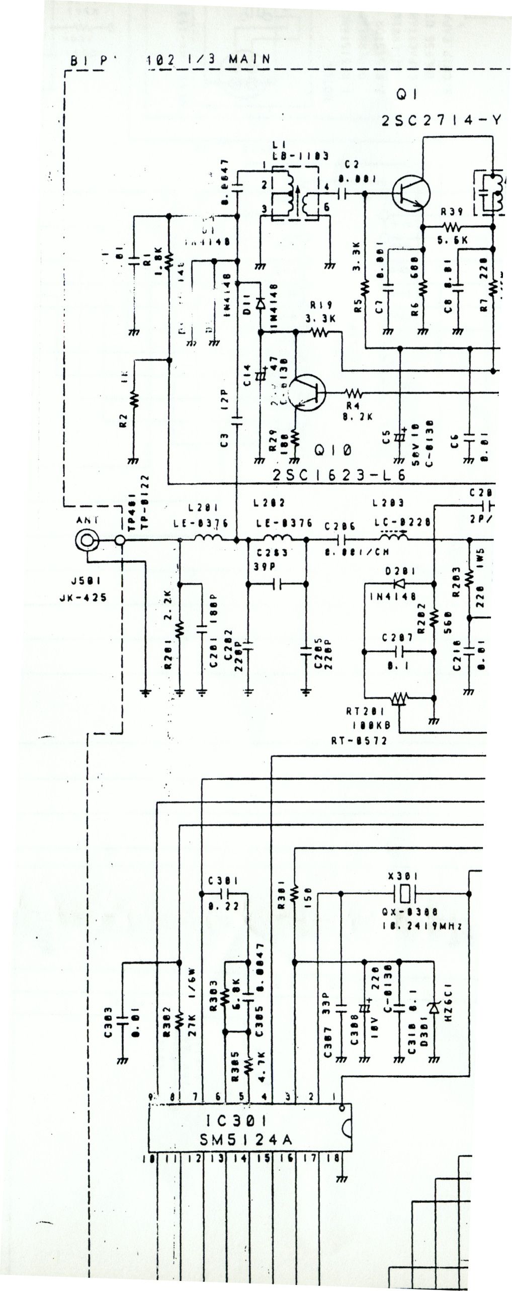
AR-103 Internal Photos Door Open, Front Panel Panel Removed, Uniden CB Visible Detail View, Uniden CB Interface Panel PCB Bottom, Microphone removed for clarity Detail, Second PCB Panel, PCB Removed PCB, Top View
Operational Description
WIZARD® Work Zone Alert and Information Radio GENERAL DESCRIPTION The WIZARD is a safety device which broadcasts prerecorded traffic alert and warning voice messages to the motoring public to prevent accidents and improve traffic flow. It employs the Citizens Band radio to air these messages. The messages are transmitted at regular fixed intervals of 30, 60, or 90 seconds as determined by the operator of the WIZARD. Three messages - each with a length of up to 18 seconds - may be recorded for transmission. A typical message takes 12 seconds. The WIZARD can broadcast any one of the prerecorded messages on 2 selected CB radio channels in a sequential manner. As an example, MESSAGE # 2 might be selected for broadcast. It will be transmitted on channel A (the first CB channel assigned). Immediately thereafter, the same message could be broadcast on channel B if a second CB channel was assigned and active. With a standard configuration, the operator can choose channel 3, 9, 17,19, 21, or 36. Channel 19 is the favorite channel because it is the choice of truckers. However, on request to the factory, any of the 40 normal CB channels may be designated as one of the 6 available. SEQUENCE OF OPERATION 1. The operator selects the time interval between messages, and assigns one of the 6 available channels as Channel A. If desired, another channel may be assigned as channel B. Using the microphone, an alert message can be recorded. If a suitable message has previously been recorded, it can be selected instead. The message can be previewed by pressing the PUSH TO LISTEN switch. It can be re-recorded if needed to improve clarity and completeness. Once set up, the mode is switched to TRANSMIT, and the rest is automatic. 2. The WIZARD begins by examining channel A for activity. If the activity on this channel is below the factory set threshold, the channel is considered clear and the message is broadcast. If the channel is found to be "busy", activity is continuously monitored until it is found to be clear. The message is broadcast immediately after the channel is found to be clear. Once the message has been transmitted, the interval timer starts the countdown to the next channel A transmission. While it is counting down, the Wizard checks to see if channel B has been enabled. If so, activity is monitored on that channel until it is clear. Then the message is broadcast. 3. In a typical configuration, the channel chosen to be channel B is likely to be a relatively quiet channel that will usually be clear at first try. However, If channel B should be “busy” for very long, it will not be allowed to interfere with the next scheduled channel A transmission. Thus, if channel B is busy for more than 20 seconds, no message will be broadcast on this channel for this cycle. After the next channel A transmission, the system will test channel B again and transmit promptly when the channel is determined to be clear. IMPORTANT NOTE A UNIDEN (brand) Citizens Band transceiver model PRO 510 XL as produced by the manufacturer is used as the transmitter for the WIZARD. The F.C.C. I.D. number for this transceiver is AMW3K2-317. Please refer to the appropriate documents for this make and model of transceiver for details on the operation of this device. This unit is very similar to the previously approved unit (NB3103) except that a different Uniden model CB is used and the control circuitry is driven by a microprocessor rather than discrete components.
RF Exposure Info
MPE Calculations FCC § 1.1307, Radio Frequency Exposure The EUT described in this report has been evaluated to the MPE limits for General Population/Uncontrolled Environment. As the manufacturer does not specify or sale any antenna with the radio the MPE calculations are based on commercially available CB antennas. According to Section 1.1310 of the FCC rules, the uncontrolled RF exposure limit for this frequency range is 180/f 2 (mW/cm 2 ). To comply with the exposure limits for this section, humans must not be too close to the transmit antenna. The following formula was used to calculate the minimum safe distance from the antenna that must be maintained during use (no time averaging was used): S = (PG)/(4πR 2 ) Where, S = Power Density P = Output Power at the Antenna Terminals in mW G = Gain of Transmit Antenna (linear gain) R = Distance from Transmitting Antenna in cm For this device, the calculation is as follows: (Based on worst case power and frequency) S = FCC Limit = 180/(26.9848) 2 mW/ cm 2 = 0.25 mW/ cm 2 P = Output Power = 3550 mW G* = Antenna Gain = 2.15 dBi = INVLOG(2.15/10) = 1.64 *Antenna Gain based on an ideal ½-wave dipole. Therefore: R = 43cm (Continuous operation) From this calculation, the minimum safe distance is 43 cm for continuous operation. Based on the worst- case usage of the device the source-based time averaging would be a 40% duty cycle. This would reduce the minimum safe distance to be 17.2 cm. R = 17.2 cm (Source-based time-averaging) The antenna for this radio is either located on top of a construction trailer roof or on top of a road construction vehicle and will be located greater than 17.2cm from personnel. For this reason the minimum safe distance is met by the typical mounting of the antenna. )()(25.0464.13550××÷×=πmWR
Test Report
Document 6919-01, Rev. 0 FCC ID: NB31032 FCC Certification Test Report Washington Laboratories, Ltd January 2002 FCC Certification Test Report for Highway Technologies, Inc. NB31032 January 15, 2002 Prepared for: Highway Technologies, Inc. 81 Texaco Road Mechanicsburg, PA 17050 Prepared By: Washington Laboratories, Ltd. 7560 Lindbergh Drive Gaithersburg, Maryland 20879 FCC Certification Test Report Document 6919-01, Rev. 0 FCC ID: NB31032 FCC Certification Test Report Washington Laboratories, Ltd January 2002 FCC Certification Test Program FCC Certification Test Report for the Highway Technologies, Inc. AR-103 Wizard NB31032 January 15, 2002 WLL JOB# 6919 Prepared by: Brian J. Dettling Documentation Specialist Reviewed by: Michael F. Violette President Document 6919-01, Rev. 0 FCC ID: NB31032 FCC Certification Test Report Washington Laboratories, Ltd January 2002 ii Abstract This report has been prepared on behalf of Highway Technologies, Inc. to support the attached Application for Equipment Authorization. The test report and application are submitted for a Citizens Band (CB) radio under Part 95 of the FCC Rules and Regulations. This Federal Communication Commission (FCC) Certification Test Report documents the test configuration and test results for a Highway Technologies, Inc. AR- 103 Wizard. Testing was performed on an Open Area Test Site (OATS) of Washington Laboratories, Ltd, 7560 Lindbergh Drive, Gaithersburg, MD 20879. Site description and site attenuation data have been placed on file with the FCC's Sampling and Measurements Branch at the FCC laboratory in Columbia, MD. Washington Laboratories, Ltd. has been accepted by the FCC and approved by NIST NVLAP (NVLAP Lab Code: 200066-0) as an independent FCC test laboratory. The Highway Technologies, Inc. AR-103 Wizard complies with the limits for a Citizens Band (CB) radio under Part 95 of the FCC Rules and Regulations. Document 6919-01, Rev. 0 FCC ID: NB31032 FCC Certification Test Report Washington Laboratories, Ltd January 2002 iii Table of Contents Abstract......................................................................................................ii 1 Introduction.................................................................................................................1 1.1 Compliance Statement..........................................................................................1 1.2 Test Scope..........................................................................................................1 1.3 Contract Information............................................................................................1 1.4 Test Dates...........................................................................................................1 1.5 Test and Support Personnel..................................................................................1 1.6 Abbreviations.......................................................................................................2 2 Equipment Under Test..................................................................................................3 2.1 EUT Identification & Description..........................................................................3 2.2 Test Configuration................................................................................................4 2.3 Testing Algorithm.................................................................................................4 2.4 Test Location.......................................................................................................4 2.5 Measurements......................................................................................................4 2.5.1 References.......................................................................................................4 2.6 Measurement Uncertainty.....................................................................................4 3 Test Equipment............................................................................................................5 4 Test Results.................................................................................................................5 4.1 RF Power Output: (FCC Part §2.1046)...............................................................5 4.2 Occupied Bandwidth: (FCC Part §2.1049)..........................................................6 4.3 Spurious Emissions at Antenna Terminals (FCC Part §2.1051.............................10 4.4 Radiated Spurious Emissions: (FCC Part §2.1053).............................................20 4.4.1 Test Procedure..............................................................................................20 List of Tables Table 1. Device Summary....................................................................................................3 Table 2: Test Equipment List...............................................................................................5 Table 3. RF Power Output...................................................................................................5 Table 4. Occupied Bandwidth Results..................................................................................6 Table 5. Conducted Spurious Emission Limits.....................................................................10 Table 6. Radiated Spurious Emissions Limits.......................................................................20 Table 7: Radiated Emission Test Data, Channel 3...............................................................21 Table 8: Radiated Emission Test Data, Channel 19.............................................................22 Table 9: Radiated Emission Test Data, Channel 36.............................................................23 Document 6919-01, Rev. 0 FCC ID: NB31032 FCC Certification Test Report Washington Laboratories, Ltd January 2002 iv List of Figures Figure 1. Occupied Bandwidth, Channel 3 (26.98 MHz)...................…
Text truncated - open the document above for the full version.
Test Report
Document 6919-01, Rev. 0 FCC ID: NB31032 FCC Certification Test Report Washington Laboratories, Ltd January 2002 FCC Certification Test Report Addendum for Highway Technologies, Inc. NB31032 April 02, 2002 Prepared for: Highway Technologies, Inc. 81 Texaco Road Mechanicsburg, PA 17050 Prepared By: Washington Laboratories, Ltd. 7560 Lindbergh Drive Gaithersburg, Maryland 20879 FCC Certification Test Report Document 6919-01, Rev. 0 FCC ID: NB31032 FCC Certification Test Report Washington Laboratories, Ltd January 2002 FCC Certification Test Program FCC Certification Test Report Addendum for the Highway Technologies, Inc. AR-103 Wizard NB31032 April 2, 2002 WLL JOB# 6919 Prepared by: Gregory M. Snyder Chief EMC Engineer Document 6919-01, Rev. 0 FCC ID: NB31032 FCC Certification Test Report Washington Laboratories, Ltd January 2002 ii Abstract This report addendum has been prepared on behalf of Highway Technologies, Inc. to address the FCC issues contained in FCC Correspondence Reference Number: 22257 for the Highway Technologies, Inc. AR-103 Wizard; FCC ID: NB31032. Document 6919-01, Rev. 0 FCC ID: NB31032 FCC Certification Test Report Washington Laboratories, Ltd January 2002 iii Table of Contents ABSTRACT II 1 INTRODUCTION...............................................................................1 1.1 COMPLIANCE STATEMENT................................................................1 1.2 TEST SCOPE...................................................................................1 1.3 CONTRACT INFORMATION.................................................................1 1.4 TEST DATES..................................................................................1 1.5 TEST AND SUPPORT PERSONNEL........................................................1 2 TEST EQUIPMENT............................................................................2 3 TEST RESULTS.................................................................................2 3.1 EMISSION DESIGNATION CALCULATION...............................................2 3.2 FREQUENCY STABILITY: (FCC PART §2.1055).......................................3 3.3 MODULATION CHARACTERISTICS: (FCC PART §2.1047); AUDIO FREQUENCY RESPONSE...............................................................................................5 3.4 MODULATION CHARACTERISTICS: (FCC PART §2.1047); MODULATION LIMITING................................................................................................7 List of Tables Table 1: Test Equipment List.........................................................................2 Table 2: Frequency Stability Over Temperature..................................................4 Table 3: Frequency Stability Over Voltage........................................................5 List of Figures Figure 1: Audio Frequency Response...............................................................6 Figure 2. Modulation Limiting........................................................................7 Document 6919-01, Rev. 0 FCC ID: NB31032 FCC Certification Test Report Washington Laboratories, Ltd January 2002 Page 1 of 7 1 Introduction 1.1 Compliance Statement The Highway Technologies, Inc. AR-103 Wizard complies with the limits for a Citizens Band (CB) radio device under Part 95 of the FCC Rules and Regulations. 1.2 Test Scope This test report addendum provides the test results for frequency stability, modulation characteristics, and calculation of the emission designator. 1.3 Contract Information Customer: Highway Technologies, Inc. 81 Texaco Road Mechanicsburg, PA 17050 Purchase Order Number: 1165 Quotation Number: 59604 1.4 Test Dates Testing was performed from March 22 to April 1, 2002. 1.5 Test and Support Personnel Washington Laboratories, LTD Greg Snyder, Santo Lavorata Document 6919-01, Rev. 0 FCC ID: NB31032 FCC Certification Test Report Washington Laboratories, Ltd January 2002 Page 2 of 7 2 Test Equipment Table 1 shows a list of the test equipment used for measurements along with the calibration information. Table 1: Test Equipment List Equipment Serial Number Date Calibrated Calibration Due Hewlett-Packard 8901B Modulation Analyzer 223893 8/27/01 8/27//02 B&K Precision 4040A Sweep/Function Generator N/A N/A N/A Racal-Dana 1992 Frequency Counter 2894 1/16/02 1/16/03 Tenney Engineering TR64 Temp. Chamber 11128 5/7/01 5/7/02 BK Precision 1610 Power Supply 145-08663 N/A N/A Fluke 87 Multimeter 55150371 6/8/01 6/8/02 3 Test Results 3.1 Emission Designation Calculation The following formula was used to calculate the necessary bandwidth and emission designator for the Wizard. Necessary Bandwidth: 2M+2D M = Maximum Modulation Frequency D = Maximum Deviation Frequency M = 2000 Hz D = 2000 Hz 2(2000) + 2(2000) = 8 kHz Type of emission: A3E Therefore: Emissions Designator = 8K00A3E Document 6919-01, Rev. 0 FCC ID: NB31032 FCC Certification Test Report Washington Laboratories, Ltd January 2002 Page 3 of 7 3.2 Frequency Stability: (FCC Part §2.1055) Frequency as a function of temperature and voltage variation shall be maintained within the FCC-prescribed tolerances. The temperature stability was measured with the unit in an environmental chamber used to vary the temperature of the sample. The sample was held at each temperature step to allow the temperature of the sample to stabilize. The EUT is powered by DC voltage supplied externally. The power requirements for the EUT include the following: Low DC Voltage of 10.2 Vdc (85% of 12 Vdc) High DC Voltage of 13.8 Vdc (115% of 12 Vdc) The frequency stability of the transmitter was examined at the voltage extremes and for the temperature range of -30°C to +50°C. The carrier frequency was measured while the EUT was in the temperature chamber. The reference frequency of the EUT was measured at the ambient room temperature with the frequency counter. The following are the reference frequencies at ambient for the Low, Middle, and High channels. Document 6919-01, Rev. 0 FCC ID: …
Text truncated - open the document above for the full version.
Test Setup Photos
Emissions Test Setup
Contact Information
Applicant
David C. Johnson(Vice President)
717 691-8007Fax: 717 697-0813
Technical Contact
Washington Laboratories, Ltd.Gregory M Snyder
[email protected]301/ 417-0220
7560 Lindbergh Drive · Gaithersburg, Maryland · United States
Non-Technical Contact
Washington Laboratories, Ltd.Brian J Dettling
[email protected]301/ 417-0220
Technical Specifications
| # | Rule Parts | Frequency Range | Power Output | Emission | Tolerance |
|---|---|---|---|---|---|
| 1 | 95D | 26.965 MHz - 27.405 MHz | 3.5 W | 8K00A3E | 0.0050000000 ppm |
Other Applications from Highway Technologies Inc

NB31033
Mar 15, 2004Work Zone Alert and Information Radio
Equipment Class
TNB - Licensed Non-Broadcast Station TransmitterNB3103
Sep 25, 1997CB Transceiver
Equipment Class
CXX - Communications Rcvr for use w/ licensed Tx and CBs