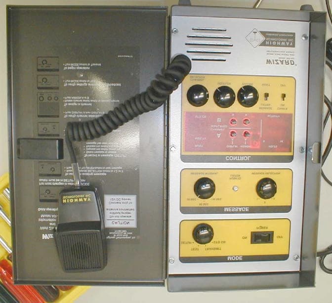
NB31033Work Zone Alert and Information Radio
Highway Technologies Inc
Click to zoom
Application Details
- Equipment Class
- TNB - Licensed Non-Broadcast Station Transmitter
- Date of Grant
- Mar 15, 2004
- Application Purpose
- Original Equipment
- Date of Application
- Mar 15, 2004
- Equipment Note
- Work Zone Alert and Information Radio
- Frequency Range
- 26.96500000 - 27.40500000
- Company
- Highway Technologies Inc
- Country
- United States
Documents & Files
Document Text
Text extracted from the exhibit documents filed with the FCC. Open a document above to read the original.
Users Manual
IZARD W THE Wizard Messages - Suggested Guidlines Wizard will accept any message. Each message can be up to 15 sec- onds long. However, to maximize effectiveness, please follow the following guidelines as much as possible. Bear in mind that the Wizard is an FCC-approved device, intended for specific traffic advice, not generic messages (such as “Drive safely”). The antenna for this device must be mounted on top of the roof of the vehicle or on top of the construction site trailer away from near- by personnel. All personnel must remain at least 8“ from an unob- structed antenna to avoid extended periods of RF exposure. 1. Minimize background noise Recording in a quiet area (in a vehi- cle or off site) is best. When recording on site, try to choose a break in the traffic noise and hold the mic close to the mouth. 2. Keep the message short Most messages can be delivered in less than 10 seconds. Include only enough information to get the mes- sage across. 3. Keep the message relevant A pattern of broadcasting outdated or not at the moment applicable messages will eventually cause them to be ignored. 4. Include key information If the message only concerns north- bound traffic or a particular exit or location, say so. 5. Use a higher pitch Female voices are more likely to get every- one’s attention. Extremely low male voices do not transmit as well. 6. Speak clearly Be sure to enunciate and speak slowly enough to avoid run-together words 7. Be Pleasant In many situations, the message may be heard sever- al times. An unpleasant message will be annoying. 8. Identify the authority Messages should first announce the author- ity giving the message, i.e. “This is the Colorado DOT” or “This is the Maryland State Police”. This gives credibility to the message that follows. Highway Technologies, Inc. 81 Texaco Road, Mechanicsburg, PA 17050 717 691-8007 CASE Height – 5” Width – 8” Depth – 3“ Weight – 5 lbs. Epoxy Powder Coat Mounting – Dash or seat POWER 12v Neg. Grd. Connector – 2 pin Amphenol Fuse – 5 amp TRANSMISSION 5 Watts Output Transmit Interval - 30 to 90 sec. Messages - any 1 of 3 user recordable Transmit Channels - 1 or 2 of any CB channel (1-40) ANTENNA Not Supplied Connector – Std., PL259 Recommended Antennas: Wilson 500 American Antenna– K40 RF Safety Warning STANDARD SPECIFICATIONS THE W ® Highwa y Tech nolog ies, I nc 81 Texaco Road • Mechanicsburg , PA 17050 • 717-691-8007 Wizard Field Operations Procedures A guide for settings and message selection under varying operating conditions Work Zone alert and Information Radio IZARD Elimination of Licensing The Federal Communications Commission has ruled that Citizens Band Radio Service operators are no longer required to obtain an FCC license to operate their CB equipment. In doing so, the FCC also permits CB stations to operate without station identification. Elimination of individual station licenses results in no lessening of the operating privileges or responsibilities of CB users. An operator of a CB radio station is still required to comply with the Communications Act and with the rules of CB Radio Service. Rules You Should Know In common with all other CB operators, you must comply with the general rules prohibiting music, profanity, promotion of illegal activities, selling of merchandise or services, and blasting others off the air with illegally amplified transmitters. Although one-way communications are generally not allowed, operation of the Wizard for its intended purpose is permitted. Rule 18 (d) provides specific permission to establish one-way communications concerning highway conditions to assist travelers. Since Rule 7 (b) reserves Channel 9 for emergency communications or travelers assistance, channel 9 may be a good choice as channel B. Why a Wizard? With trucks logging more than 50 billion vehicle miles on the nation's roads, more maintenance and more work zones increases the opportunity for more accidents. Higher speeds, inattentive driving and closer spacing contribute to rear-end vehicle collisions and hazardous conditions for road construction workers. The Wizard® is designed to provide advanced warning of impending traffic slowdowns to give all vehicles, especially heavy trucks, the necessary time to stop. The Wizard is a completely portable wireless broadcasting system adaptable to any work site, sending localized messages on selected CB channels. The Wizard counts down the selected interval for sending, listens for a break in activity on channels 9 and 19 (or other user selected and emergency CB chan- nels), and broadcasts when clear. Care is taken to not interfere with normal CB communication between vehicles. A short message alerts the driver to slow down. The message can be broad- cast on a second user selected channel if desired. Messages can be changed at the site, broadcast distances adjusted for traffic backup, and message frequency modified to compensate for average speeds. WARNING The Citizens Band (CB) Radio Service is under the jurisdiction of the Federal Communications Commission (FCC). Any adjustments or alterations which alter the performance of the transceiver's original FCC type acceptance, or change the frequency determining method, are strictly prohibited. Replacement or substitution of crystals, transistors, ICs, regulator diodes, or any other part of a unique nature, with parts other than those recommended by Highway Technologies, Inc., may cause violation of the technical regulations of Part 95 of the FCC rules or violation of type acceptance require- ments of Part 2 of the rules. This radio has been type accepted and certified by the FCC. The Wizard is not intended for unattended operation. An operator should be in control of the system at all times. Elimination of Licensing Rules You Should Know Standard Menu Structure Although the Wizard is capable of many variations of set- tings, experience to date has shown that most operators use only channel 19 with a brief message. If this is your inten…
Text truncated - open the document above for the full version.
Cover Letter(s)
Highway Technologies, Inc. • 81 Texaco Road, Mechanicsburg, PA 17050 • 717 691-8007 HARRISBURG, PENNSYLVANIA HIGHWAY TECHNOLOGIES, INC February 28, 2004 American Telecommunications Certification Body, Inc. 6731 Whittier Avenue Suite C110 McLean, VA 22101 To Whom It May Concern: Please be advised that Highway Technologies, Inc. authorizes Washington Laboratories, Inc. to act on our behalf, until otherwise notified, for applications submitted to American Telecommunications Certification Body, Inc. (ATCB). We certify that we are not subject to denial of federal benefits, that includes FCC benefits, pursuant to Section 5301 of the Anti-Drug Abuse ACT of 1988, U.S.C. 862. Further, no party, as defined in 47 CFR 1.2002(b), to the application is subject to denial of federal benefits, that includes FCC benefits. Thank you for your attention to this matter. Sincerely, David C. Johnson David C. Johnson Vice President
Cover Letter(s)
American Telecommunications Certification Body Inc. 6731 Whittier Ave, McLean, VA 22101 March 15, 2004 RE: FCC ID: NB31033_ATCB001198 Attention: Brian J. Dettling I have a few comments on this Application. 1. Please note that the 7 inch separation distance mentioned in the manual puts this device in the portable category. Please note that the separation distance needs to be 20cm or 7.9 inches. Please revise the manual for mobile use separation distances. Please use either the standard 20cm separation or alternately please use 7.9 or 8 inches as the separation distance. 2. Please provide the tune-up procedure for this device. Dennis Ward mailto:[email protected] The items indicated above must be submitted before processing can continue on the above referenced application. Failure to provide the requested information may result in application termination. Correspondence should be considered part of the permanent submission and may be viewed from the Internet after a Grant of Equipment Authorization is issued. Please do not respond to this correspondence using the email reply button. In order for your response to be processed expeditiously, you must submit your documents through the AmericanTCB.com website. Also, please note that partial responses increase processing time and should not be submitted. Any questions about the content of this correspondence should be directed to the sender.
Cover Letter(s)
Response to ATCB Comments FCC ID: NB31033 1 Washington Laboratories, Ltd. 7560 LINDBERGH DRIVE GAITHERSBURG, MD 20879 (301) 417 – 0220 FAX # (301) 417 - 9069 March 16, 2004 Mr. Dennis Ward American Telecommunications Certification Body Inc. 6731 Whittier Ave McLean, VA 22101 RE: Comments of March 15, 2004 APPLICATION: NB31033 Highway Technologies, Inc. Dear Mr. Ward: Below are the comments that you have provided regarding the application for certification referenced above. Our responses to those comments are in bold italic. Many responses refer you to additional exhibit(s) which has been uploaded to the application folder at the ATCB website. Thank you for your attention. Please feel free to contact us for any additional information that you may require. Regards, Gregory M. Snyder Chief EMC Engineer, Wireless/Telco Services Manager Brian J. Dettling Documentation Specialist WLL Project: 7871 1) Please note that the 7 inch separation distance mentioned in the manual puts this device in the portable category. Please note that the separation distance needs to be 20cm or 7.9 inches. Please revise the manual for mobile use separation distances. Please use either the standard 20cm separation or alternately please use 7.9 or 8 inches as the separation distance. R. The manual has been changed to reflect the correct separation distance. Please see exhibit “Wizard User Manual rev1.pdf.” 2) Please provide the tune-up procedure for this device. Response to ATCB Comments FCC ID: NB31033 2 R. The manufacturer attests that the Uniden radio (FCC ID: AMW3K2-317) contained in the device is not operationally altered, therefore no additional tuning is required. Please see exhibit “HTI Tuning Attestation Letter.pdf.”
Cover Letter(s)
Highway Technologies, Inc. • 81 Texaco Road, Mechanicsburg, PA 17050 • 717 691-8007 HARRISBURG, PENNSYLVANIA HIGHWAY TECHNOLOGIES, INC February 28, 2004 American Telecommunications Certification Body, Inc. 6731 Whittier Avenue Suite C110 McLean, VA 22101 To Whom It May Concern: RE: Certification Application FCC ID: NB31033 Please be advised that the following exhibits are to be held confidential on behalf of Highway Technologies, Inc: Schematics Operational Description Block Diagram Parts List The application contains technical information that Highway Technologies, Inc. deems to be trade secrets and proprietary. If made public, the information might be used to the disadvantage of the applicant in the market place. Thank you for your attention to this matter. Sincerely, David C. Johnson David C. Johnson Vice President
External Photos
Overall View User Interface Module – Front User Interface Module – Back Wizard Radio Module – Top Wizard Radio Module – Front / Right Wizard Radio Module – Rear / Left Wizard Radio Module – Rear Wizard Radio Module – Bottom
ID Label/Location Info
FCC Label Model: Wizard FCC ID: NB31033 Highway Technologies, Inc. Made in USA Serial Number: xxxxxxxx ________________________ This device complies with Part 15 of the FCC rules. Operation is subject to the following two conditions: 1. This device may not cause harmful interference, and 2. This device must accept any interference received, including interference that may cause undesired operation. Patented FCC Label Location
Internal Photos
Cover Removed Uniden Radio Top View Uniden Radio Bottom (No components located under shield) End Panel of Uniden Radio Highway Technologies Control Module - Top Highway Technologies Control Module – Bottom
RF Exposure Info
MPE Calculations FCC § 1.1307, Radio Frequency Exposure The EUT described in this report has been evaluated to the MPE limits for General Population/Uncontrolled Environment. As the manufacturer does not specify or sale any antenna with the radio the MPE calculations are based on commercially available CB antennas. According to Section 1.1310 of the FCC rules, the uncontrolled RF exposure limit for this frequency range is 180/f 2 (mW/cm 2 ). To comply with the exposure limits for this section, humans must not be too close to the transmit antenna. The following formula was used to calculate the minimum safe distance from the antenna that must be maintained during use (no time averaging was used): S = (PG)/(4πR 2 ) Where, S = Power Density P = Output Power at the Antenna Terminals in mW G = Gain of Transmit Antenna (linear gain) R = Distance from Transmitting Antenna in cm For this device, the calculation is as follows: (Based on worst case power and frequency) S = FCC Limit = 180/(26.9848) 2 mW/ cm 2 = 0.25 mW/ cm 2 P = Output Power = 3960 mW G* = Antenna Gain = 2.15 dBi = INVLOG(2.15/10) = 1.64 *Antenna Gain based on an ideal ½-wave dipole. Therefore: R = 45cm (Continuous operation) From this calculation, the minimum safe distance is 45 cm for continuous operation. Based on the worst- case usage of the device the source-based time averaging would be a 40% duty cycle. This would reduce the minimum safe distance to be 18 cm. R = 18 cm (Source-based time-averaging) The antenna for this radio is either located on top of a construction trailer roof or on top of a road construction vehicle and will be located greater than 18cm from personnel. For this reason the minimum safe distance is met by the typical mounting of the antenna. )()( 25.0464.13960××÷×=πmWR
Test Report
Document 7871-01, Rev. 0 FCC ID: NB31033 FCC Certification Test Report March 2004 Washington Laboratories, Ltd. FCC Certification Test Report for Trafcon Industries, Inc. NB31033 March 12, 2004 Prepared for: Trafcon Industries, Inc. 81 Texaco Road Mechanicsburg, PA 17050 Prepared By: Washington Laboratories, Ltd. 7560 Lindbergh Drive Gaithersburg, Maryland 20879 FCC Certification Test Report Document 7871-01, Rev. 0 FCC ID: NB31033 FCC Certification Test Report March 2004 Washington Laboratories, Ltd. FCC Certification Test Report for the Trafcon Industries, Inc. Traffic Wizard Alert & Information Radio System NB31033 March 12, 2004 WLL JOB# 7871 Prepared by: Brian J. Dettling Documentation Specialist Reviewed by: Gregory M. Snyder Chief EMC Engineer Document 7871-01, Rev. 0 FCC ID: NB31033 FCC Certification Test Report March 2004 Washington Laboratories, Ltd. ii Abstract This report has been prepared on behalf of Trafcon Industries, Inc. to support the attached Application for Equipment Authorization. The test report and application are submitted for a Citizens Band (CB) radio under Part 95 of the FCC Rules and Regulations. This Federal Communication Commission (FCC) Certification Test Report documents the test configuration and test results for a Trafcon Industries, Inc. Traffic Wizard Alert & Information Radio System. Testing was performed on an Open Area Test Site (OATS) of Washington Laboratories, Ltd, 7560 Lindbergh Drive, Gaithersburg, MD 20879. Site description and site attenuation data have been placed on file with the FCC's Sampling and Measurements Branch at the FCC laboratory in Columbia, MD. Washington Laboratories, Ltd. has been accepted by the FCC and approved by NIST NVLAP (NVLAP Lab Code: 200066-0) as an independent FCC test laboratory. The Trafcon Industries, Inc. Traffic Wizard Alert & Information Radio System complies with the limits for a Citizens Band (CB) radio device under Part 95 of the FCC Rules and Regulations. Document 7871-01, Rev. 0 FCC ID: NB31033 FCC Certification Test Report March 2004 Washington Laboratories, Ltd. iii Table of Contents Abstract ............................................................................................................................... ii 1 Introduction..............................................................................................................1 1.1 Compliance Statement .........................................................................................1 1.2 Test Scope ............................................................................................................1 1.3 Contract Information............................................................................................1 1.4 Test Dates ............................................................................................................1 1.5 Test and Support Personnel .................................................................................1 1.6 Abbreviations .......................................................................................................2 2 Equipment Under Test .............................................................................................3 2.1 EUT Identification & Description .......................................................................3 2.2 Test Configuration ...............................................................................................3 2.3 Testing Algorithm................................................................................................3 2.4 Test Location .......................................................................................................4 2.5 Measurements ......................................................................................................4 2.5.1 References........................................................................................................4 2.6 Measurement Uncertainty....................................................................................4 3 Test Equipment ........................................................................................................5 4 Test Results ..............................................................................................................6 4.1 RF Power Output: (FCC Part §2.1046) ...............................................................6 4.2 Occupied Bandwidth: (FCC Part §2.1049) ..........................................................6 4.3 Spurious Emissions at Antenna Terminals (FCC Part §2.1051...........................8 4.4 Radiated Spurious Emissions: (FCC Part §2.1053)...........................................13 4.4.1 Test Procedure ...............................................................................................13 5 MPE Calculations ..................................................................................................17 5.1 FCC § 1.1307, Radio Frequency Exposure .......................................................17 List of Tables Table 1. Device Summary................................................................................................... 3 Table 2: Test Equipment List.............................................................................................. 5 Table 3. RF Power Output .................................................................................................. 6 Table 4. Occupied Bandwidth Results................................................................................ 6 Table 5. Conducted Spurious Emission Limits .................................................................. 8 Table 6. Radiated Spurious Emissions Limits .................................................................. 13 Table 7: Radiated Emission Test Data, Channel 1 .......................................................... 14 Table 8: Radiated Emission Test Data, Channel 20 ........................................................ 15 Table 9: Radiated Emi…
Text truncated - open the document above for the full version.
Test Setup Photos
Emissions Test Configuration
Contact Information
Applicant
David C. Johnson(Vice President)
717 691-8007Fax: 717 697-0813
Technical Contact
Washington Laboratories, Ltd.Gregory M Snyder
[email protected]301/ 417-0220
7560 Lindbergh Drive · Gaithersburg, Maryland · United States
Technical Specifications
| # | Rule Parts | Frequency Range | Power Output | Emission | Tolerance |
|---|---|---|---|---|---|
| 1 | 95D | 26.965 MHz - 27.405 MHz | 4 W | 8K00A3E | 0.0050000000 ppm |
Other Applications from Highway Technologies Inc
NB31032
Jul 22, 2002Highway Safety Transmitter
Equipment Class
TNB - Licensed Non-Broadcast Station TransmitterNB3103
Sep 25, 1997CB Transceiver
Equipment Class
CXX - Communications Rcvr for use w/ licensed Tx and CBs