ND28000000000Spread Spectrum Transmitter
Cadco Systems Inc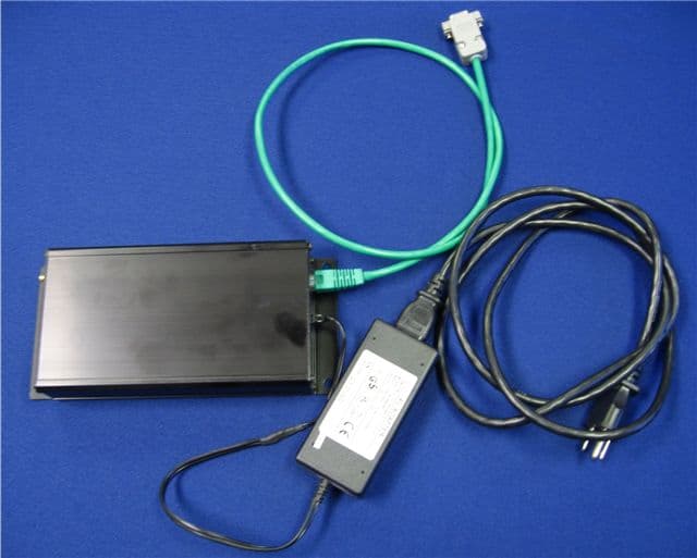
Click to zoom
Application Details
- Equipment Class
- DSS - Part 15 Spread Spectrum Transmitter
- Date of Grant
- Feb 01, 2007
- Application Purpose
- Original Equipment
- Date of Application
- Feb 01, 2007
- Equipment Note
- Spread Spectrum Transmitter
- Frequency Range
- 902.50000000 - 927.00000000
- Company
- Cadco Systems Inc
- Country
- United States
Documents & Files
Document Text
Text extracted from the exhibit documents filed with the FCC. Open a document above to read the original.
Cover Letter(s)
=CADCO svsTrn4s 1t23t2007 Equipment Autorisation Division Federal Communications Commission 7435 Oakland Mills Road Columbia, MD 21046 FCC lD: ND28000000000 Product Name: Dia-Trac Request for Confi dentialitv Pursuant to Sections 0.457 and 0.459 of the commissions rules, we hereby request that the following documents be held confidential: o schematics-4129908_SCH.pdf,413002A_SCH_PDF.pdf;TRUSION_CADCO BOX.pdf o Blockdiagnams- 91 5MHz_RADIO_SEVER_BLOCKDIAGRAM. pdf;91 5MHz-RADIO-TRUCK-BLOCKDIA GRAM. pdf; J 1 708-TRUCK-CONTROLLER-CARD-DIAGMM. pdf e Parts List(sFBOM412-0990-120revB.pdf . User Manual- Installation FINAL.pdf o Internal Photographs-lnternal Photos.pdf; Picture 043.jpeg User manual- Since this product is a professional install the Installation manual is not given to the end user. It is intended to be given to the installation professionals only. Internal photos- Since this is a professional install product access to the equipment is limited to authorized dealers or the installation group. These materials contain trade secrets and proprietary information and are not customarily released to the public. The public disclosure of this information might be harmfulto the company and provide unjustified benefits to our competitor. Dated this By: 2363 Menitt Dr Garland Tx7504l 972271365r //' Dav or /ga/.r', oy 20 g7 ,v u ,4rctr' Printed Title: anp On behalf of : 4zz >7/ 3b5/ Telephone:
Operational Description
1/10/2007 Operational Description The DIA-TRAC Product will be used to collect various types of data from a truck. This data is collected and stored in flash memory until the truck approaches a designated hub. At this point a communication link is established and the data is transmitted to the host server. The data will be transmitted to the server using a pair of 915 Mhz ISM Band frequency hopping radios. The DIA-TRAC Product consists of two systems. The Truck System, which is used to collect, store, and transmit the data. And the Server Radio System, which is used to receive the data from the trucks, then to send the data to a Data Collection Server thru a RS-232 interface. The following is a list of components that make up each of the systems. Truck System - The Truck system consists of the following: 1. Truck Radio Module 2. Antennae/GPS Dome assembly. 3. Wiring Harness to connect the Truck Module to Antennae/GPS Dome. 4. Wiring Harness to connect the Truck Module to the Sensors 5. Wiring Harness to connect the Truck Module to the J-Buss and +12 VDC power. 6. Current sensors and temperature sensor. Server Radio System – The Server Radio System consist of the following: 1. Server Radio Module. 2. AC power adapter with +9 VDC out. 3. Antennae. 4. RF Cable to connect Server Module to antennae. 5. RS232 cable to connect Server Radio Module to a Server Computer. The J1708 Controller Card, which is located inside the DIA-TRAC Truck Radio Module housing, is the device that gathers and stores the information. The various types of collected data would include: 1. J-Buss information. The J1708 Controller Card will collect data from the J-Buss system, which is standard on most of the trucks manufactured today. The DIA-TRAC system is configurable to collect any or all the data that is available from the J-Buss system. 2. GPS information. The J1708 Controller Card has a RS-232 interface to collect data from the GPS module. The controller card collects the time stamp and the location from the external GPS module. 3. Current data. There are 3 analog inputs connected to the DB-15 Analog Input Connector. These will be connected to current sensors to monitor various points of the trucks charge and discharge systems. 4. Temperature data. There is 1 analog input connected to the DB-15 Analog Input Connector. This will be connected to a temperature sensor to monitor the batteries temperature. 5. There is also an optional RS-232 interface labeled FPS on the box. This port is for future uses. The J1708 Controller card (412-0990-000) uses a Phillips LPC2212FBD144 Microcontroller CPU (U13) to control all of its functions. The LP2212FBD144 uses a 14.7456 Mhz Crystal (Y2) to set the clock of the CPU. The operational program and the boot program are programmed into the LPC2212’s internal memory. There is an additional memory device M29W641DH (U14), this is a flash memory device used to store the accumulated truck data. Another flash memory device AT240C4(U11) is for future use. It is not used at this time. The DS3777 (U25) is the J-Buss transceiver interface between the external connector P1, and the LPC2212 Microcontroller. This IC serves as a level translator between the trucks J-Buss system and the microcontroller. The TL16C754BPN IC is a quad serial interface. This IC interfaces the GPS system (J8), the unused FPS connector (J9), and the interface to the 413-0002-000 Radio Board. This chip uses a 3.6864 Mhz crystal (Y3) to set the timing. The Truck Radio Module will be powered by the battery system of the truck. The power supply input comes in on pins 7 and 8 of connector P1. This input voltage will be approx +12 to +14 VDC. The power input then goes thru a 1 amp fuse, a low pass filter and is applied to U27 a LT1076HVIR step- down switching regulator. The input voltage is converted down to +6VDC. The +6 VDC is routed to the 413-002-000 to provide power to the radio board. The +6VDC is also routed to U2 which provides +5VDC. The +5VDC is routed to U4 to provide +3.3VDC. The +3.3VDC is routed to U18 to provide 1.8VDC. All of the various power supply voltages are used to provide power to the components that populate the 412-0990-000. 413-002-000 915 Mhz Radio Board is also located inside the DIA-TRAC truck module housing. This board handles the communication between the J1708 Controller card and the Data Collection Server at the data collection area. The 915 MHz Radio (413-0002-000) uses a Atmel Mega128 Microcontroller CPU (U9) to control all of its functions. The Atmel Mega128 uses a 14.7456 Mhz Crystal (Y1) to set the clock on the CPU. The operational program and the boot program are programmed into the Mega128’s internal memory. The AT45B011 (U2) is a 1Mbit SRAM memory chip used to store a new program if a software upgrade should become necessary. The Chipcon CC1021 (U4) is the radio transceiver chip used to transmit and receive the data. The radio is programmed to transmit with the following specifications. Frequency Band: 902-928 Mhz Power Output: .823Watt Channel Separation: 500 Khz Channel Bandwidth: 307Khz Number of Channels 50 Hop interval 200 mS (198mS active dwell, 2 mS blanking period) Hop Sequence pseudo-random The transmitted RF signal from the CC1021 is sent to a MAAPSS095 (U11). (U11) is a 1 watt power amplifier. The amplifier is turned on and off by the Mega128 CPU (U2). The control line from the CPU is connected to a SN74AHCT1G04 (U8) a single inverter buffer which controls a NDS352PCT mosfet switch (Q1). The switch is configured to bias the amplifier to its on an off state. The amplified RF signal from (U11) is routed to the MASWSS0006 (SW2) RF switch. This switch is also controlled by the Mega128 (U2). The same control line from (U2) is used to control another SN74AHCT1G04 (U7). (U7) is used to toggle the RF switch (SW2) between transmit and receive modes. The amplified RF signal is routed thru (FL1) a 915 Mhz center frequency filter to the RF Output Connector (P1). The DIA-TRAC Truck Modu…
Text truncated - open the document above for the full version.
Test Report
Nemko Test Report: 2024RUS1 Applicant: Cadco Systems 2363 Merritt Drive Garland, TX 75041 USA Equipment Under Test: Dia-Track Truck Diagnostics and Tracking System (E.U.T.) In Accordance With: FCC Part 15, Subpart C, 15.247 Frequency Hopping Transmitters Tested By: Nemko USA Inc. 802 N. Kealy Lewisville, Texas 75057-3136 TESTED BY: DATE: 17 January 2007 Kevin Rose, Senior Wireless Engineer APPROVED BY: DATE: 17 January 2007 David Light, Senior Wireless Engineer Total Number of Pages: 40 Nemko USA, Inc. FCC PART 15, SUBPART C FREQUENCY HOPPING SPREAD SPECTRUM TRANSMITTER EUT: Dia-Track Truck Diagnostics and Tracking System PROJECT NO.:2024RUS1 Page 2 of 40 Table of Contents SECTION 1. SUMMARY OF TEST RESULTS 3 SECTION 2. EQUIPMENT UNDER TEST (E.U.T.) 5 SECTION 3. CHANNEL SEPARATION 7 SECTION 4. TIME OF OCCUPANCY 12 SECTION 5. PEAK POWER OUTPUT 17 SECTION 6. SPURIOUS EMISSIONS (ANTENNA CONDUCTED) 18 SECTION 7. SPURIOUS EMISSIONS (RADIATED) 24 SECTION 8. TEST EQUIPMENT LIST 28 ANNEX A - TEST DETAILS 29 ANNEX B - TEST DIAGRAMS 38 Nemko USA, Inc. FCC PART 15, SUBPART C FREQUENCY HOPPING SPREAD SPECTRUM TRANSMITTER EUT: Dia-Track Truck Diagnostics and Tracking System PROJECT NO.:2024RUS1 Page 3 of 40 Section 1. Summary of Test Results Manufacturer: Cadco Systems Part No.: 413-0002-000revA Serial No.: None General: All measurements are traceable to national standards. These tests were conducted on a sample of the equipment for the purpose of demonstrating compliance with Part 15, Subpart C, Paragraph 15.247 for Frequency Hopping Spread Spectrum devices. Radiated tests were conducted is accordance with ANSI C63.4-2003. Radiated emissions are made on an open area test site. A description of the test facility is on file with the FCC. New Submission Production Unit Class II Permissive Change Pre-Production Unit THIS TEST REPORT RELATES ONLY TO THE ITEM(S) TESTED. THE FOLLOWING DEVIATIONS FROM, ADDITIONS TO, OR EXCLUSIONS FROM THE TEST SPECIFICATIONS HAVE BEEN MADE. See “ Summary of Test Data”. Nemko USA Inc. authorizes the above named company to reproduce this report provided it is reproduced in its entirety and for use by the company’s employees only. Any use which a third party makes of this report, or any reliance on or decisions to be made based on it, are the responsibility of such third parties. Nemko USA Inc. accepts no responsibility for damages, if any, suffered by any third party as a result of decisions made or actions based on this report. This report applies only to the items tested. Nemko USA, Inc. FCC PART 15, SUBPART C FREQUENCY HOPPING SPREAD SPECTRUM TRANSMITTER EUT: Dia-Track Truck Diagnostics and Tracking System PROJECT NO.:2024RUS1 Page 4 of 40 Summary Of Test Data NAME OF TEST PARA. NO. RESULT Powerline Conducted Emissions 15.207(a) NA Channel Separation 15.247(a)(1) Complies Time of Occupancy 15.247(a)(1) Complies 20 dB Occupied Bandwidth 15.247(a)(1) Complies Peak Power Output 15.247(b) Complies Spurious Emissions (Antenna Conducted) 15.247(d) Complies Spurious Emissions (Radiated) 15.247(d) Complies Footnotes: The device is not powered via AC mains. Nemko USA, Inc. FCC PART 15, SUBPART C FREQUENCY HOPPING SPREAD SPECTRUM TRANSMITTER EUT: Dia-Track Truck Diagnostics and Tracking System PROJECT NO.:2024RUS1 Page 5 of 40 Section 2. Equipment Under Test (E.U.T.) General Equipment Information Frequency Band: 902 – 928 MHz 2400 – 2483.5 MHz 5725 – 5850 MHz Operating Frequency Range: 902.5-927.0 MHz Number of Channels: 50 Channel Spacing: 500 kHz User Frequency Adjustment: Software controlled Nemko USA, Inc. FCC PART 15, SUBPART C FREQUENCY HOPPING SPREAD SPECTRUM TRANSMITTER EUT: Dia-Track Truck Diagnostics and Tracking System PROJECT NO.:2024RUS1 Page 6 of 40 Description of EUT The Dia-Track Truck Diagnostics and Tracking System is composed of a Truck Radio Module and a Server Radio Module. The Server Radio Module will be located in a truck stop and the Truck Radio Module will be located inside a truck. System Diagram Nemko USA, Inc. FCC PART 15, SUBPART C FREQUENCY HOPPING SPREAD SPECTRUM TRANSMITTER EUT: Dia-Track Truck Diagnostics and Tracking System PROJECT NO.:2024RUS1 Page 7 of 40 Section 3. Channel Separation NAME OF TEST: Channel Separation PARA. NO.: 15.247(a)(1) TESTED BY: Kevin Rose DATE:12 January 2007 Test Results: Complies. Measurement Data: See 20 dB BW plot Measured 20 dB bandwidth: 332 kHz Channel Separation: 500 kHz Equipment Used: 1036-1478-1479-1629 Measurement Uncertainty: 1X10 -7 ppm Temperature: 22°C Relative Humidity: 49% Nemko USA, Inc. FCC PART 15, SUBPART C FREQUENCY HOPPING SPREAD SPECTRUM TRANSMITTER EUT: Dia-Track Truck Diagnostics and Tracking System PROJECT NO.:2024RUS1 Page 8 of 40 Test Data – Channel Separation Nemko USA, Inc. FCC PART 15, SUBPART C FREQUENCY HOPPING SPREAD SPECTRUM TRANSMITTER EUT: Dia-Track Truck Diagnostics and Tracking System PROJECT NO.:2024RUS1 Page 9 of 40 Test Data – 20 dB Bandwidth Low Channel Nemko USA, Inc. FCC PART 15, SUBPART C FREQUENCY HOPPING SPREAD SPECTRUM TRANSMITTER EUT: Dia-Track Truck Diagnostics and Tracking System PROJECT NO.:2024RUS1 Page 10 of 40 Test Data – 20 dB Bandwidth Mid Channel Nemko USA, Inc. FCC PART 15, SUBPART C FREQUENCY HOPPING SPREAD SPECTRUM TRANSMITTER EUT: Dia-Track Truck Diagnostics and Tracking System PROJECT NO.:2024RUS1 Page 11 of 40 Test Data – 20 dB Bandwidth High Channel Nemko USA, Inc. FCC PART 15, SUBPART C FREQUENCY HOPPING SPREAD SPECTRUM TRANSMITTER EUT: Dia-Track Truck Diagnostics and Tracking System PROJECT NO.:2024RUS1 Page 12 of 40 Section 4. Time of Occupancy NAME OF TEST: Time of Occupancy PARA. NO.: 15.247(a)(1) TESTED BY: Kevin Rose DATE: 12 January 2007 Test Results: Complies. Measurement Data: Maximum Dwell Time On Any Channel: Equipment Used: 1036-1478-1479-1629 Measurement Uncertainty: 1X10 -7 ppm Temperature: 22 °C Relative Humidity: 45 % Nemko USA, Inc. FCC PART 15, SUBPART C FREQUENCY HOPPING SPREAD SPECTRUM TRANSMITTER EUT: Dia-Track Truck Diagnostics and Tr…
Text truncated - open the document above for the full version.
Contact Information
Applicant
Steven Johnson(President)
Test Firm
Nemko Dallas, Inc.Michael Cantwell
Technical Specifications
| # | Rule Parts | Frequency Range | Power Output |
|---|---|---|---|
| 1 | 15C | 902.5 MHz - 927 MHz | 813.00 mW |
Other Applications from Cadco Systems Inc
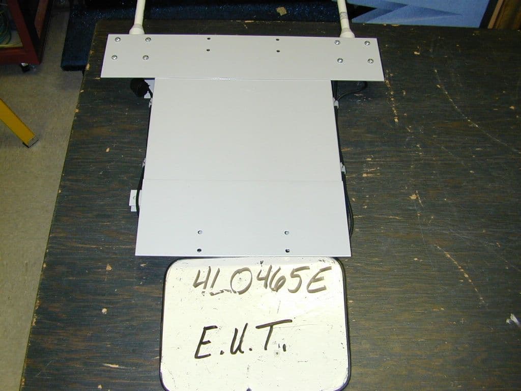
ND2PAP2400
Sep 28, 2004Power Access Point
Equipment Class
DTS - Digital Transmission System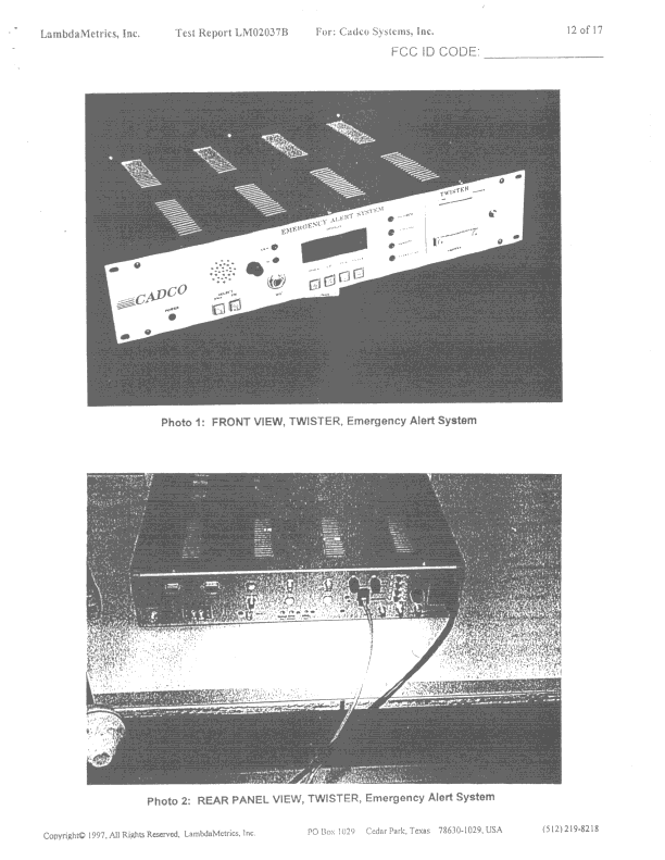
ND2EAS
Sep 30, 1998EAS Encoder/Decoder
Equipment Class
EAD - Part 11 Emergency Alert Devices