ND2PAP2400Power Access Point
Cadco Systems Inc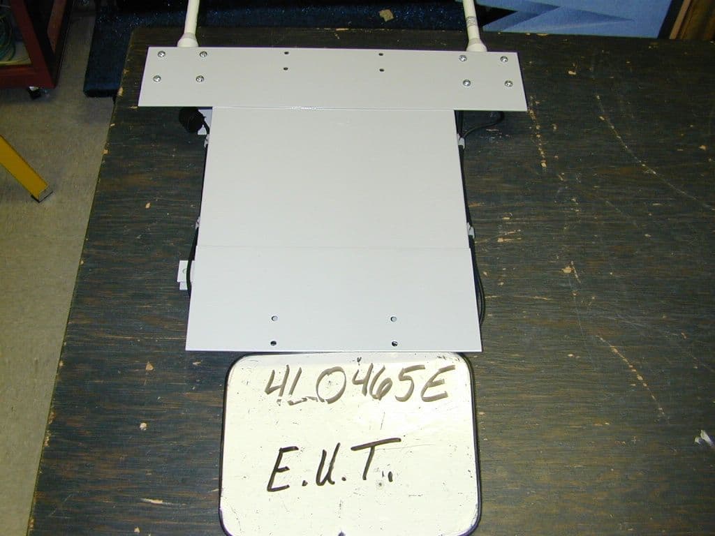
Click to zoom
Application Details
- Equipment Class
- DTS - Digital Transmission System
- Date of Grant
- Sep 28, 2004
- Application Purpose
- Original Equipment
- Date of Application
- Sep 28, 2004
- Equipment Note
- Power Access Point
- Frequency Range
- 2412.00000000 - 2462.00000000
- Company
- Cadco Systems Inc
- Country
- United States
Documents & Files
Document Text
Text extracted from the exhibit documents filed with the FCC. Open a document above to read the original.
Users Manual
CADCO SYSTEMS DUAL RADIO HOT SPOT & SERVER START GUIDE QUICK Inventory 1. - 5 ft. Mast Pipe- 4 Clamps- Bag of Bolts - Access Point - Ethernet- RS232- Power - Server - AC Adapter Note: Verify that all equipment has been recieved and is of the correct type. Installation 2. Step 1. Make sure you have all ofthe appropriate tools, wrench &socket and screwdriver. Step 2. Position one set of clampsaround the center satellite pole.Partially screw in eight of the bolts.Leave space to slide in the adjacentpole.Step 4. Align the Access Point so thatthe top of the box is even with the topof the satellite. Fasten the box to thetop of the pole with the small clamp andremaining bolts. Step 3. Slide the adjacent pole betweenthe clamps. Fasten the bolts. Position thesecond set of clamps around bothpoles and fasten the remaining bolts. Server Setup 3. Molex Connector To Linkstar RCST RS232 Ethernet Truck Stop Line of Site to the Roadway Line of Site to the Parking Area 4. Hot Spot & Server Positioning This product intentionally uses RF enerergy and has been evaluated for RF exposure at a distance of 20 cm (8 inches). The antenna used with this product must be mounted to maintain a separation distance of 20cm to all persons. Operation at a separation distance less than 20 cm (8 inches) from the radiating element to nearby persons will expose nearby persons to RF levels that exceed the FCC rules for RF exposure and will violate FCC rules and regulations. THIS EQUIPMENT COMPLIES WITH PART 15 OF THE FCC RULES. ANY CHANGES OR MODIFICATIONS NOT EXPRESSLY APPROVED BY THE MANUFACTURER COULD VOID THE USER'S AUTHORITY TO OPERATE THE EQUIPMENT. WARNING CADCO SYSTEMS 2363 Merritt Dr. Garland, TX 75041 Phone: (972) 271-3651 Toll Free: (800) 877-2288 Fax: (972) 271-3654
ID Label/Location Info
PAP2400 FCC LABEL Label Dimensions: The label format as presented is actual size. Length: 1.256” Width: 0.916” Label Location:
RF Exposure Info
Prediction of MPE limit at a given distance Equation from page 18 of OET Bulletin 65, Edition 97-01 where:S = power density P = power input to the antenna G = power gain of the antenna in the direction of interest relative to an isotropic radiator R = distance to the center of radiation of the antenna Maximum peak output power at antenna input terminal:28.00(dBm) Maximum peak output power at antenna input terminal:630.9573(mW) Antenna gain(typical):8(dBi) Maximum antenna gain:6.309573(numeric) Prediction distance:20(cm) Prediction frequency:2400(MHz) MPE limit for uncontrolled exposure at prediction frequency:1(mW/cm^2) Power density at prediction frequency:0.792009(mW/cm^2) 2 4R PG S π =
Test Report
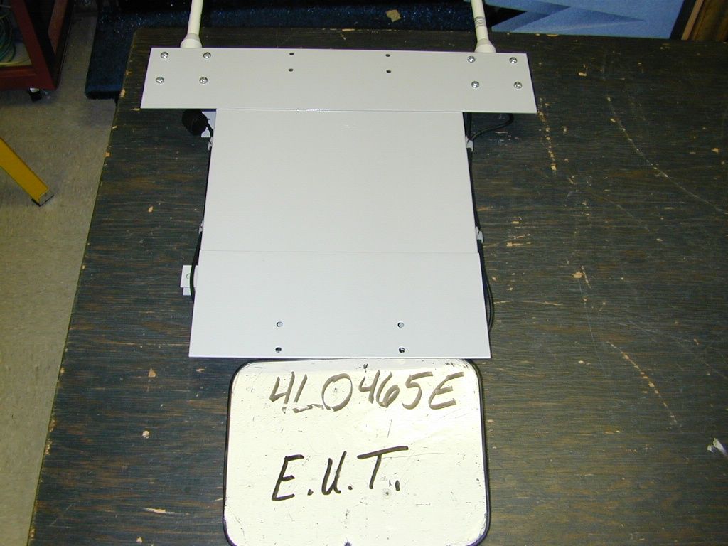
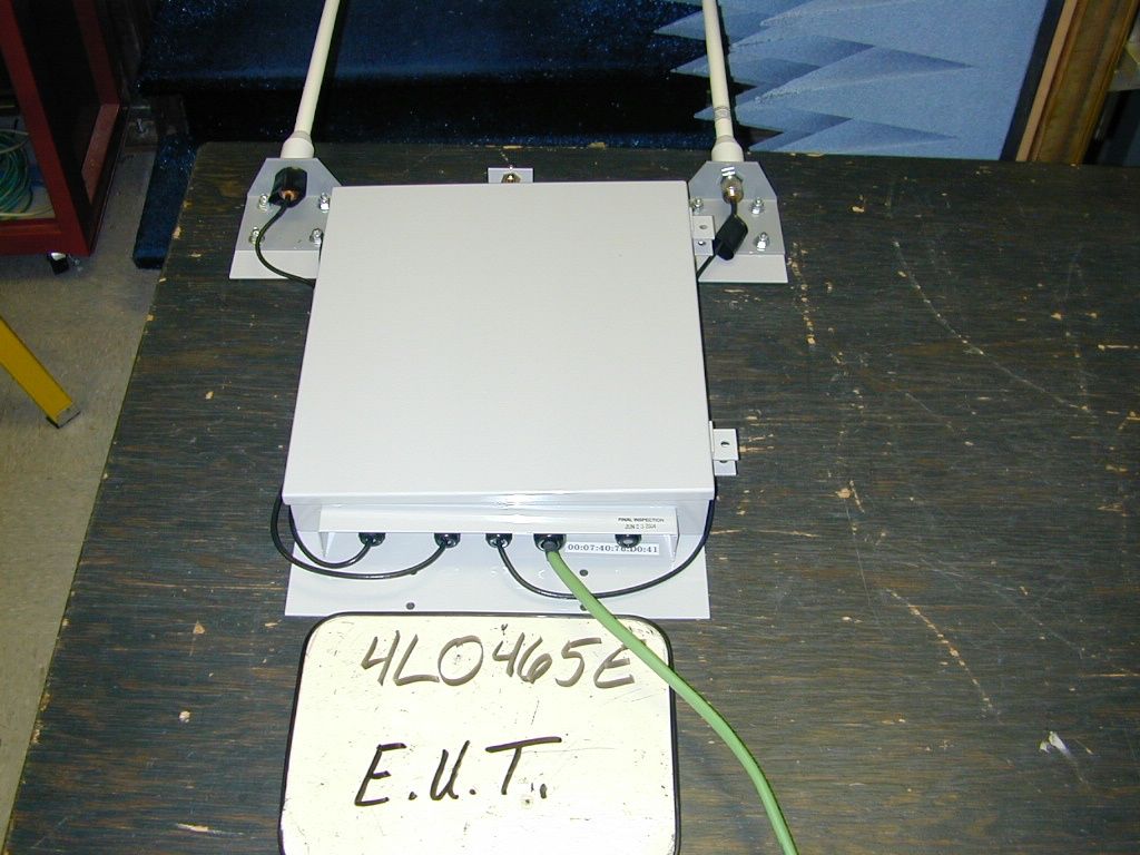
Nemko Test Report: 4L0465RUS1 Applicant: Cadco Systems 2363 Merritt Drive Garland, TX Equipment Under Test: Power Access Point 2400 (E.U.T.) In Accordance With: FCC Part 15, Subpart C, 15.247 Direct Sequence Spread Spectrum Transmitters Tested By: Nemko Dallas Inc. 802 N. Kealy Lewisville, Texas 75057-3136 Authorized By: Tom Tidwell, Frontline Group Manager Date: 25_Aug_2004 Total Number of Pages: 39 Nemko Dallas FCC PART 15, SUBPART C SPREAD SPECTRUM TRANSMITTER EQUIPMENT: Power Access Point 2400 TEST REPORT NO.: 4L0465RUS1 Page 2 of 39 Table of Contents Section 1. Summary of Test Results.................................................................... 3 Section 2. Equipment Under Test (E.U.T.) ......................................................... 5 Section 3. Powerline Conducted Emissions........................................................ 7 Section 4. Minimum 6 dB Bandwidth...............................................................10 Section 5. Maximum Peak Output Power .........................................................14 Section 6. Spurious Emissions (Conducted) .....................................................15 Section 7. Spurious Emissions (Radiated) ........................................................20 Section 8. Peak Power Spectral Density ...........................................................23 Section 9. Test Equipment List .............................................................................27 ANNEX A - TEST DETAILS................................................................................28 ANNEX B - TEST DIAGRAMS ...........................................................................36 Nemko Dallas FCC PART 15, SUBPART C SPREAD SPECTRUM TRANSMITTER EQUIPMENT: Power Access Point 2400 TEST REPORT NO.: 4L0465RUS1 Page 3 of 39 Section 1. Summary of Test Results Manufacturer: Cadco Systems Model No.: Power Access Point 2400 Serial No.: 1000 General: All measurements are traceable to national standards. These tests were conducted on a sample of the equipment for the purpose of demonstrating compliance with Part 15, Subpart C, Paragraph 15.247 for Direct Sequence Spread Spectrum devices. Radiated tests were conducted is accordance with ANSI C63.4-2001. Radiated emissions are made on an open area test site. A description of the test facility is on file with the FCC. New Submission Production Unit Class II Permissive Change Pre-Production Unit THIS TEST REPORT RELATES ONLY TO THE ITEM(S) TESTED. THE FOLLOWING DEVIATIONS FROM, ADDITIONS TO, OR EXCLUSIONS FROM THE TEST SPECIFICATIONS HAVE BEEN MADE. NONE NVLAP LAB CODE: 100426-0 Nemko Dallas Inc. authorizes the above named company to reproduce this report provided it is reproduced in its entirety and for use by the company’s employees only. Any use which a third party makes of this report, or any reliance on or decisions to be made based on it, are the responsibility of such third parties. Nemko Dallas Inc. accepts no responsibility for damages, if any, suffered by any third party as a result of decisions made or actions based on this report. This report applies only to the items tested. Nemko Dallas FCC PART 15, SUBPART C SPREAD SPECTRUM TRANSMITTER EQUIPMENT: Power Access Point 2400 TEST REPORT NO.: 4L0465RUS1 Page 4 of 39 Summary Of Test Data NAME OF TEST PARA. NO. SPEC. RESULT Powerline Conducted Emissions 15.207(a) 48 dBμV Complies Minimum 6 dB Bandwidth 15.247(a)(2) >500 kHz Complies Maximum Peak Power Output 15.247(b)(1)<1 Watt Complies Spurious Emissions (Antenna Conducted) 15.247(c) -20 dBc/100kHz Complies Spurious Emissions (Restricted Bands) 15.247(c) < 74 dBuV/m Peak < 54 dBuV/m Avg Complies Peak Power Spectral Density 15.247(d) +8 dBm/3kHz Complies Footnotes: Nemko Dallas FCC PART 15, SUBPART C SPREAD SPECTRUM TRANSMITTER EQUIPMENT: Power Access Point 2400 TEST REPORT NO.: 4L0465RUS1 Page 5 of 39 Section 2. Equipment Under Test (E.U.T.) General Equipment Information Frequency Band: 2412 to 2462 MHz Modulation: DBPSK – 1 Mbps, DQPSK - 2 Mbps (11Msps) Channel Spacing: 5 MHz User Frequency Adjustment: Software controlled Note: It was determined that the worst-case operating mode was 11 Mbps DQPSK. Full testing was performed on three channels at 11 Mbps. Nemko Dallas FCC PART 15, SUBPART C SPREAD SPECTRUM TRANSMITTER EQUIPMENT: Power Access Point 2400 TEST REPORT NO.: 4L0465RUS1 Page 6 of 39 Description of EUT An 802.11b Access Point with LNA & Power Amp in a weather tight enclosure System Diagram Nemko Dallas FCC PART 15, SUBPART C SPREAD SPECTRUM TRANSMITTER EQUIPMENT: Power Access Point 2400 TEST REPORT NO.: 4L0465RUS1 Page 7 of 39 Section 3. Powerline Conducted Emissions NAME OF TEST: Powerline Conducted Emissions PARA. NO.: 15.207(a) TESTED BY: Brian Boyea DATE: 7/6/04 Test Results: Complies. Measurement Data: See attached plots. Measurement Uncertainty: +/- 1.7 dB Nemko Dallas FCC PART 15, SUBPART C SPREAD SPECTRUM TRANSMITTER EQUIPMENT: Power Access Point 2400 TEST REPORT NO.: 4L0465RUS1 Page 8 of 39 Test Data – Powerline Conducted Emissions Dallas Headquarters: 802 N. Kealy Lewisville, TX 75057 Tel: (972) 436-9600 NEMKO Dallas, Inc. Fax: (972) 436-2667 Conducted Emissions Powerline Voltage Measurement CompleteXJob # : 4L0465ETest # : CEPV-01 PreliminaryPage1of1 Client Name :Cadco Systems EUT Name :Power Access Point 2400 EUT Model # :PAP2400 EUT Part # :776-0000-000 EUT Serial # :1000 EUT Config. :802.11b Specification :FCC 15.207 Reference : Transducer # :1258Temp. (deg. C) :23Date : 07/06/04 HP Filter # :968Humidity (%) :42Time : 10:30 A.M. Cable 1 # :1551EUT Voltage :120 VacStaff : Brian Boyea Cable 2 # :1266EUT Frequency : 60 HzLocation : SR Detector 1 # :966Peak Bandwidth: 10kHzPhoto ID: 4L0465E CEPV-01 Detector 2 # :1464QP Bandwidth10kHz Limiter # :N/AAvg. Bandwidth10kHz Meas.EUTDetectorLimitMeterPathTransducerCorrectedSpec.limitCR/SLPass Freq. TestTypeTypeReadingLossFactorReading(dBuV)Diff.Fail (MHz)Point(P,QP, A)(QP, A)(dBuV)(dB)(dB)(dBuV)Q.P.Avg.(dB)Unc.Com…
Text truncated - open the document above for the full version.
Contact Information
Applicant
Steven Johnson(President)
Test Firm
Nemko Dallas, Inc.Michael Cantwell
Technical Specifications
| # | Rule Parts | Frequency Range | Power Output |
|---|---|---|---|
| 1 | 15C | 2.41 GHz - 2.46 GHz | 3.98 W |
Other Applications from Cadco Systems Inc
ND28000000000
Feb 01, 2007Spread Spectrum Transmitter
Equipment Class
DSS - Part 15 Spread Spectrum Transmitter
ND2EAS
Sep 30, 1998EAS Encoder/Decoder
Equipment Class
EAD - Part 11 Emergency Alert Devices