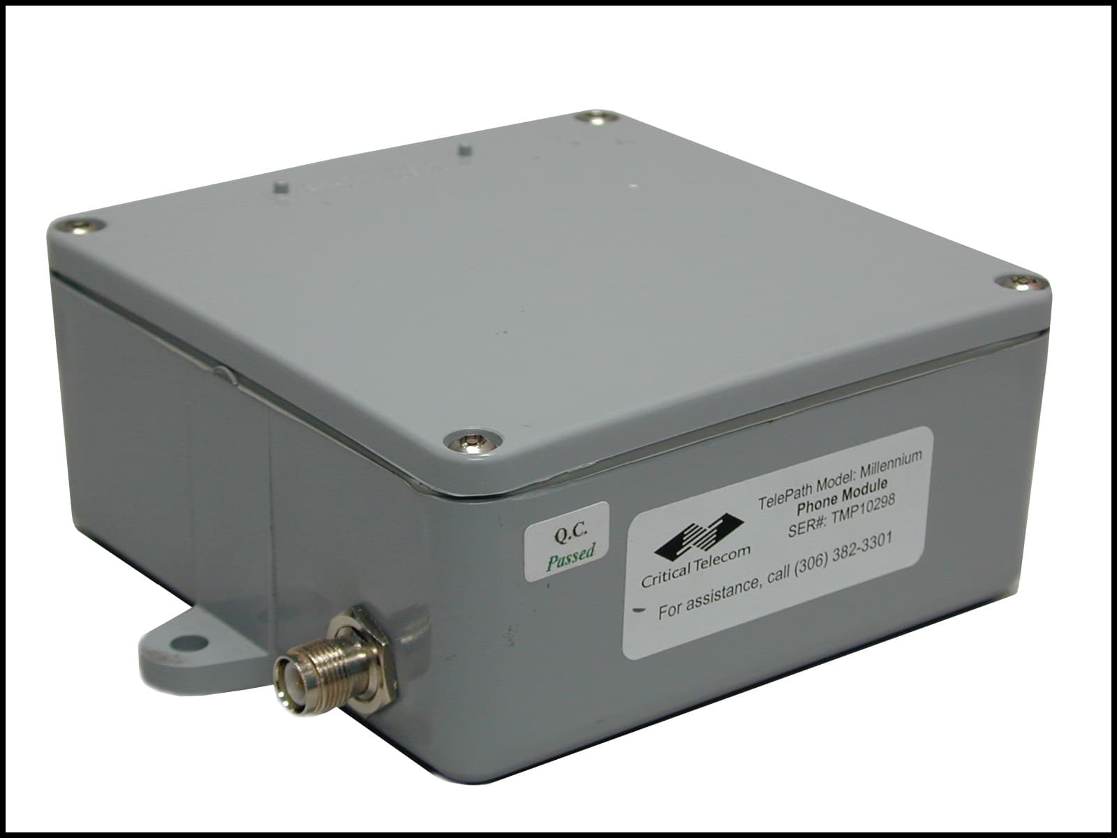
NE9TM2000TelePath Millenium System
Critical Telecom Corp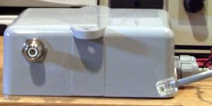
Click to zoom
Application Details
- Equipment Class
- DSS - Part 15 Spread Spectrum Transmitter
- Date of Grant
- Dec 13, 2000
- Application Purpose
- Original Equipment
- Date of Application
- Jun 25, 2000
- Equipment Note
- TelePath Millenium System
- Frequency Range
- 908.43000000 - 925.32000000
- Company
- Critical Telecom Corp
- Country
- Canada
Documents & Files
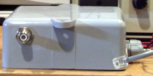
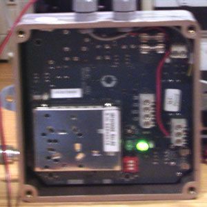
Document Text
Text extracted from the exhibit documents filed with the FCC. Open a document above to read the original.
Users Manual
USER MANUAL TelePATH Millennium Copyright Critical Control Corp. 2000, 1999 Table of Contents 1) Overview .................................................................................................................... 2 2) Description and Features........................................................................................... 2 3) Installation..................................................................................................................2 A) Equipment Required..........................................................................................................2 B) Line Module and Antenna..................................................................................................2 i)Mounting Module ............................................................................................................................ 2 ii)Mounting Antenna........................................................................................................................... 2 iii)Antenna Connection ....................................................................................................................... 2 iv)Tip and Ring Connection ................................................................................................................ 3 v)Power and Ground Connections .................................................................................................... 3 vi)Channel Selection........................................................................................................................... 3 C) Phone Module and Antenna ..............................................................................................3 i)Mounting Module ............................................................................................................................ 3 ii)Mounting Antenna........................................................................................................................... 3 iii)Antenna Connection ....................................................................................................................... 3 iv)Tip and Ring Connection ................................................................................................................ 3 v)Power and Ground Connections ................................................................................................... 3 vi)Channel Selection........................................................................................................................... 4 D) System Registration ..........................................................................................................4 i)How can I tell that registering is needed?....................................................................................... 4 ii)What should I do ?.......................................................................................................................... 4 iii)How do I know it worked ?.............................................................................................................. 4 E) Ganged Multiple Line Installations .....................................................................................4 i)Burst-sync Connections.................................................................................................................. 4 ii)Channel Selection........................................................................................................................... 4 iii)Registration..................................................................................................................................... 4 F) Craft Interface ...................................................................................................................5 4) Service Information .................................................................................................... 5 5) Specifications............................................................................................................. 6 6) Limited Warranty........................................................................................................ 7 7) Customer Information ................................................................................................ 7 A) Analogue Device Warnings ...............................................................................................7 B) Industry Canada Warnings ................................................................................................7 C) Radio Interference Statement............................................................................................8 TelePATH2 1) OVERVIEW Thank you for purchasing a TelePATH Millennium digital wireless link from Critical Control. Your new TelePATH Millennium is a carefully engineered, high-quality, durable product. It is designed to deliver the quality and performance you expect from telecommunications equipment. The TelePATH Millennium digital wireless link is a cost effective solution for point-to-point voice and data communication. The system provides a reliable toll-quality wireless connection between a public telephone and the wire connection back to the central office. The TelePATH Millennium may be used for both temporary and permanent installations where circumstances make conventionally wired installations impractical. 2) DESCRIPTION AND FEATURES The TelePATH Millennium system consists of two Modules, two antennas, and two coaxial cables. Once installed, the components provide a transparent wireless link between a phone and the central office. The “Line Module” connects to the central office line. The “Phone Module” connects to the phone. The Phone and Line Modules are similar in appearance but each is clearly labelled to avoid confusion. The TelePATH Millennium has been specifically designed for use with the Nortel Millennium payphone and supports all of its functions. The TelePA…
Text truncated - open the document above for the full version.
Users Manual
TelePATH 2 1) OVERVIEW Thank you for purchasing a TelePATH Millennium digital wireless link from Critical Control. Your new TelePATH Millennium is a carefully engineered, high-quality, durable product. It is designed to deliver the quality and performance you expect from telecommunications equipment. The TelePATH Millennium digital wireless link is a cost effective solution for point-to-point voice and data communication. The system provides a reliable toll-quality wireless connection between a public telephone and the wire connection back to the central office. The TelePATH Millennium may be used for both temporary and permanent installations where circumstances make conventionally wired installations impractical. 2) DESCRIPTION AND FEATURES The TelePATH Millennium system consists of two Modules, two antennas, and two coaxial cables. Once installed, the components provide a transparent wireless link between a phone and the central office. The “Line Module” connects to the central office line. The “Phone Module” connects to the phone. The Phone and Line Modules are similar in appearance but each is clearly labelled to avoid confusion. The TelePATH Millennium has been specifically designed for use with the Nortel Millennium payphone and supports all of its functions. The TelePATH Millennium system may be used only with approved antennas (see the Specifications section for a list of approved antennas). Either module may be used with any of the three antennas. The TelePATH Millennium system must be professionally installed in compliance with FCC part 15 subpart C and Industry Canada’s Radio Standards Specification RSS-210, Issue 2, Rev.1. 3) INSTALLATION A) EQUIPMENT REQUIRED • Digital Multi-Meter • 5/32” Security Allen Key • 1/8” Width Flat Blade Screw Driver • #8 Philips Head Screw Driver • Cordless Drill with appropriate bits (Optional) • Static Ground Strap B) LINE MODULE AND ANTENNA I) MOUNTING MODULE Identify and locate the Line Module in an area suitable for obtaining access to dial-tone and power. The location selected must also allow for connection to the antenna. Fix the Module to the desired location using the two screws provided. II) MOUNTING ANTENNA To comply with FCC requirements for RF exposure, antennas must be installed such that no persons will be closer than 20 cm from any part of the antenna while operational. Using the hardware provided, select and install the Line antenna in the desired location. For mast type antenna installations keep the mast as close as possible to the Line Module. Antennas must be installed a least two meters above grade. Masts are not provided as part of the TelePATH Millennium system. Where directional antennas are employed, the antenna elements must be oriented vertically (Figure 1). For optimal system performance the antenna should be mounted as far above grade as possible. Where Phantom antennas are employed, mounting is possible by drilling a 1” hole through the surface on which the antenna will be mounted provided the surface is no thicker than ¼”. Alternatively, an L bracket with a 1” hole and three mounting holes is supplied.
Users Manual
TelePATH 3 III) ANTENNA CONNECTION Connect the Line Module to the Line antenna using the coaxial cable provided. For long-term out-door installations it recommended that the antenna connections be protected from corrosion by some suitable method (i.e. Tape Coat). IV) TIP AND RING CONNECTION Route the cable, providing tip and ring signalling from the central office, through the appropriate strain relief connector and terminate the tip and ring wires at the screw terminals labelled “T” and “R” respectively (Figure 2). Tighten the strain relief connector onto the cable finger tight. Do not use a wrench! It is recommended that ground strap be used when making connections to the printed circuit boards in the Module enclosures. Failure to use a ground strap may result in permanent damage to the Module from static discharge! V) POWER AND GROUND CONNECTIONS The Line Module will operate from DC voltages in the range of 10 Vdc to 36 Vdc. Route cable providing the DC power and ground through the appropriate strain relief connector and terminate the wires at the screw terminals labelled “+” and “-“. Terminate the earth ground wire at the screw terminal labelled “E” (Figure 1). Tighten the strain relief connector onto the cable finger tight. Do not use a wrench! VI) CHANNEL SELECTION Any of the eight channels may be selected; however, your selection must be the same for both the Line and Phone Modules. Using the dip-switches (Figure 6), select the desired channel and then momentarily press the button labelled “RESET”. If interference is encountered, repeat the procedure with a different channel. C) PHONE MODULE AND ANTENNA I) MOUNTING MODULE Identify and locate the Phone Module in a secure area suitable for obtaining access to power and the phone (Booth Header, Pedestal Module, etc.). The location selected must allow for connection to the antenna. Fix the Module to the desired location using the two screws provided. II) MOUNTING ANTENNA To comply with FCC requirements for RF exposure, antennas must be installed such that no persons will be closer than 20 cm from any part of the antenna while operational. Using the hardware provided, select and install the Line antenna in the desired location. For mast type antenna installations keep the mast as close as possible to the Line Module. Antennas must be installed a least two metres above grade. Masts are not provided as part of the TelePATH Millennium system. Where directional antennas are employed, the antenna elements must be oriented vertically (Figure 1). For optimal system performance the antenna should be mounted as far above grade as possible. Where Phantom antennas are employed, mounting is possible by drilling a 1” hole through the surface on which the antenna will be mounted provided the surface is no thicker than ¼”. Alternatively, an L bracket with a 1” hole and three mounting holes is supplied. III) ANTENNA CONNECTION Connect the Phone Module to the antenna using the coaxial cable provided. For long-term out-door installations it recommended that the antenna connections be protected from corrosion by some suitable method (i.e. Tape Coat). IV) TIP AND RING CONNECTION Route the cable, providing tip and ring signalling to the phone, through the appropriate strain relief connector and terminate wires at the screw terminals labelled “T” and “R” (Figure 3). Tighten the strain relief connector onto the cable finger tight. Do not use a wrench!
Users Manual
TelePATH 6 5) SPECIFICATIONS General Digital voice coding 32 kbps ADPCM Voice delay <10 ms end-to-end Signalling Hook status, Pulse dialing, T&R polarity, Ring cadence Data Rate Up to 14.4 kbps (supports Bell 212A, V.32bis) Dimensions 6.0”x6.5”x2.5” (HxWxD) Weight 600 g Operating temperature Extended -40° to 70° C Humidity 0 to 95% non-condensing Radio Frequency Range ISM, 902-928 MHz Channels 8 RF Modulation GMSK Digital Modulation Direct Sequence Digital Spread Spectrum Bandwidth 2.3 MHz Output power 100 mW (20 dBm +/- 2 dBm) Receiver sensitivity -90 dBm @ 10e-3 BER Approved antennas 3 dBd / 5 dBi omni-directional “Phantom” (ANTENEX TRA9023NP) 6 dBd / 8 dBi directional (MAXRAD MYA-9153) 11 dBd / 13 dBi directional (MAXRAD MYA-91512) Certification IC RSS210 Issue 2, FCC Part 15 Subpart B and C Phone Interface 600 Ω, loop-start Ringing Amplitude > 45 Vrms @ 1 REN Ringing Frequency 20 Hz Ringer Waveform Sinusoidal Battery Voltage -48 Vdc Loop Current 25 mA Supply Voltage 10 to 36 Vdc Supply Power 2.75 W (max) Power Termination Screw Terminal (2 position) + / - Loop Termination Screw terminal (2 position) T / R Burst-sync Termination Screw Terminal (4 position) M, D, /D, G Cable Access Through weather resistant strain relief Antenna Termination External reverse TNC connector Protection Secondary Certification IC CS03 Issue 8, FCC Part 68 Subpart D Line Interface > 600 Ω, loop-start Ringing load < 1 REN Ring detect 40 - 120 Vrms Supply Voltage 10 to 36 Vdc Supply Power 1.75 W (max) Power Termination Screw Terminal (3 position) + / - / Earth ground Loop Termination Screw terminal (2 position) T / R Burst-sync Termination Screw Terminal (4 position) M, D, /D, G Cable Access Through weather resistant strain relief Antenna Termination External reverse TNC connector Protection Primary, Secondary Certification IC CS03 Issue 8, FCC Part 68 Subpart D Craft Support Power On LED Communication Link LED RF Receive Signal Strength Analog output, 0 to 1 Vdc Registration Push-button switch Monitor Port 3 pin header
Block Diagram
MCU (11.0592 MHz) GMSK Radio Module (902 – 928 MHz) Specific T/R Interface ADPCM CODEC (10.368 MHz) Spread Spectrum Transceiver (16.384 MHz) Test Port Channel Selection MCU Supervisor Non-volatile Memory 50 Ω Antenna TDD Sync. Interface Spread Data (1.365 Mbps) Rx Tx TDD RefClk De-spread Data (85.32 kbps) Rx Tx Clk Fsync Analog Signal Rx Tx Serial Frequency Data Configuration, Li nk sta tus , & App. status T/R Co ntro l, T/R Sta tus Serial Config Data 3 bits Serial Test Data H/ware Reset Watch- dog Strobe
Cover Letter(s)
6 – 816 First Avenue North, Saskatoon, Saskatchewan, Canada S7K 1Y3 Tel: 306 382 3301 www.cc.ca [email protected] Fax: 306 978 3301 REQUEST FOR NONDISCLOSURE OF INFORM ATION IN CERTIFICATION APPLICAT IONS 1. Identification of information to be withheld from the public • Schematics (“Line Schematic RevA.pdf” and “Phone Schematic RevA.pdf”) – 3 pages each • Parts Lists (“Line Parts List RevA.pdf” and “Phone Parts List RevA.pdf”) – 5 pages each • System Description (“Description.pdf”) – 7 pages 2. Applications in which the information appears • FCC Rules part 15 subpart C (FCC ID: NE9TM2000) • FCC Rules part 68 3. Degree to which the information is commercial in nature, or contains trade secrets All of the identified information is confidential and includes trade secrets. It is not publicly known how our product performs its tasks. The submitted schematics, parts lists, and technical description documentation reveal intellectual property that is proprietary and should not be released. 4. Degree to which the information concerns a product or service that is subject to competition All of the identified information concerns a system that is marketed in the highly competitive wireless telecommunications market. 5. How disclosure of the information will cause competitive harm Disclosure of any of the identified information could enable competitors to benefit improperly from our hard-won intellectual property and harm our competitive advantage. 6. Measures taken to keep the information confidential Confidentiality agreements have been signed with personnel who have access to this information. The identified information is stored in a secure area that is not accessible to wide-area-networks. 7. Statement of information privacy None of the identified information is available to the public, and no previous disclosures have been made to third parties. 8. Period of time over which protection is requested Projections show that the marketable life-cycle of this system is 7 years; therefore, we request confidentiality protection for a period of at least 7 years. 9. Additional information that may help the FCC in determining whether to grant the request A very large investment of time and money has been made in the development of this proprietary system. Disclosure of any of the identified information would undermine the competitive process. Signed ______________________________ Printed Michael D. Lockerbie Title El ectrical/Software Engineer
Cover Letter(s)
6 – 816 First Avenue North, Saskatoon, Saskatchewan, Canada S7K 1Y3 Tel: 306 382 3301 www.cc.ca [email protected] Fax: 306 978 3301 April 20, 2000 Federal Communicatio ns Commission 7435 Oakland Mills Road Columbia, MD 21046 USA Authority to Act as Agent to the Federal Communications Commission On o ur behalf, I appoint Electro nics Test Centre MPB Technologies Inc. to act as agent in the preparation of this application for equipment authorization to the Federal Communications Commission. I certify that submitted exhibits properly describe the device or system for which equipment authorizatio n is sought. I also certify that each unit manufactured, imported or marketed, as defined in the Commissio n’s regulations will have affixed to it a label identical to that submitted for approval with this application. Dated this20th Day ofApril 2000 Agency agreement expiration date: December 1, 2000 By:Michael D. Lockerbie SignaturePrinted Title: Electrical/Software Engineer Telephone:(306) 382-3301 Applicant: Critical Control Corp.
ID Label/Location Info
CriticalControl MFR's NO. DIMENSIONS IN COMPUTER GENERATED DRAWING FILENAME: -1 - NO. FINISHAPPD DWNCHKD SCALEDATE QTY 5/31/00 Tolerances IF DUAL DIMS: DMN INCHES PART NO. NEXT ASSY: UM SHEET OF 1 DOCUMENT NUMBERDOCUMENT NUMBER 1 LABEL, REGULATORY,TELEPATH MILLENNIUM - PHONETELEPATH MILLENNIUM - PHONE DESCRIPTION INCHES mm (inches) MM TITLE: DCN NUMBER DESCRIPTION DOCUMENT NO.DOCUMENT NO. REV (unless otherwise specified)(unless otherwise specified) .xx ± .01 ANGLES ± 1°FRACTIONS ± 1/32 FRACTIONS ± 1/32 .xxx ± .005 ANGLES ± 1° .x ± 0.25 Critical Control Corporation. Critical Control Corporation. ction without written permission fromction without written permission fromto others, copied or used for produ-This document is not to be disclosedThis document is not to be disclosed .xx ± 0.15 © 2000 18-33-P MATERIAL: 3M-3650 PLASTIC SHEET, ADHESIVE-BACKED 1.40" BLACK PRINT 1.60" WHITE 2:1 FONTS:ARIAL - 5.5ptARIAL - 4.7pt CC PART NUMBER: 61-TP-ICP REV. REMARKS ITEM DATE APPDAPPD DWN 1.1 This devices complies with Part 15 of the FCC Rules.Operation is subject to the following two rules:(1) This device may not cause harmful interference,and(2) This device must accept any interference received,including interference that may cause undesiredoperation. Made in Canada Critical Control Corp.Complies with Part 68, FCC RulesCANADA: 27641031875A Model No.: TelePath MillenniumReg. No.:FCC ID: NE9TM2000 6QQUSA-35126-OT-N
ID Label/Location Info
CriticalControl MFR's NO. DIMENSIONS IN COMPUTER GENERATED DRAWING FILENAME: -1 - NO. FINISHAPPD DWNCHKD SCALEDATE QTY 5/31/00 Tolerances IF DUAL DIMS: DMN INCHES PART NO. NEXT ASSY: UM SHEET OF 1 DOCUMENT NUMBERDOCUMENT NUMBER 1 LABEL, REGULATORY,TELEPATH MILLENNIUM - LINETELEPATH MILLENNIUM - LINE DESCRIPTION INCHES mm (inches) MM TITLE: DCN NUMBER DESCRIPTION DOCUMENT NO.DOCUMENT NO. REV (unless otherwise specified)(unless otherwise specified) .xx ± .01 ANGLES ± 1°FRACTIONS ± 1/32 FRACTIONS ± 1/32 .xxx ± .005 ANGLES ± 1° .x ± 0.25 Critical Control Corporation. Critical Control Corporation. ction without written permission fromction without written permission fromto others, copied or used for produ-This document is not to be disclosedThis document is not to be disclosed .xx ± 0.15 © 2000 18-33-L MATERIAL: 3M-3650 PLASTIC SHEET, ADHESIVE-BACKED 1.40" BLACK PRINT 1.60" WHITE 2:1 FONTS:ARIAL - 5.5ptARIAL - 4.7pt CC PART NUMBER: 61-TP-ICL REV. REMARKS ITEM DATE APPDAPPD DWN 1.1 This devices complies with Part 15 of the FCC Rules.Operation is subject to the following two rules:(1) This device may not cause harmful interference,and(2) This device must accept any interference received,including interference that may cause undesiredoperation. Made in Canada Critical Control Corp.Complies with Part 68, FCC RulesIC REN: 0.4CANADA: 27641031875A Model No.: TelePath MillenniumReg. No.:FCC REN: 0.4BFCC ID: NE9TM2000 6QQUSA-35126-OT-N
ID Label/Location Info
Note that this one system/product has two different labels (one for each line- and phone-module). The difference is only the lack of REN numbers for the phone-module's label since the phone-module does not have a ringer. Please advise whether this is the right approach. Please find attached two PDF files each of the regulatory labels for phone- and line-modules (18-33-p-rev1.1.pdf & 18-33-l-rev1.1.pdf respectively). The line-module's label has the REN numbers; the phone-module's label has not. Further, please see the drawing that indicates label placement; each label is placed at the same location of its respective enclosure. Note that the text found on the label in the placement drawing is not current.
Operational Description
T 020-MS-OM-A2 IRF9096DS T 021-MS-OM-A2 IRF9192DS T 022-MS-OM-A2 IRF9250DS Single VCO 900MHz RF Module InnoMedia Technology Inc. 3F, No 3, Industry East Rd. IX, Science-Based Industrial Park, Hsinchu, Taiwan, R.O.C. TEL : +886-3-5641299 FAX : +886-3-5641589 1999/6/8 1 1 InnoMedia IRF9XXXDS Single VCO 900MHz RF Module -------------------------------------------------------------------------------------------------------------------------------------- ---- INTRODUCTION InnoMedia IRF9XXXDS RF Module is a radio transceiver that provides all of the baseband-to-RF and RF-to-baseband signal conversion functions needed for 902 - 928 MHz digital communication. It can accompany the ALFA AIC9001 Spread Spectrum Transceiver integrated circuit to support either digital voice or data communication, in both full-duplex and half-duplex operations. The IRF9XXXDS‘s high performance, compact size and low power consumption make it ideal for portable, battery-powered wireless products such as digital cordless phone and wireless modem. It also can meet FCC part requirements to let your wireless products get FCC approval easily. Figure 1 and 2 show the typical system applications for cordless phone and wireless modem. Figure 1. Block diagram of Cordless phone Figure 2. Block diagram of Wireless modem FEATURES Antenn Ma ste r osc illa tor Voice Codec Line Interface Microprocessor SST A SI C AIC9001 PSTN RF Module IRF9XXXDS Antenn Ma ste r osc illa tor Microprocessor SST A SI C AIC9001 RF Module IRF9XXXDS Exte r na l PC (DTE) RS- 232 Driver 2 2 • Designed for 902-928 MHz wireless communication systems. • Time Division Duplexing ( TDD ). • GMSK Modulation/Demodulation. • Single conversion receiver. • Conforms to FCC part 15 requirements. • Power management for supply current minimization. • Low material cost. • Two tuning points only. • Provides 8/4/3 non-overlapping channels with AIC9001 SST chip. • Compact size (45mm x 60mm x 10 mm) RF MODULE BLOCK DIAGRAM The IRF9XXXDS RF Module is a complete combination of transmitter and receiver . The functional block diagram is shown in Figure 3. Figure3:Block Diagram of RF Module A) TRANSMITTER Antenn Loop Filte r Ga ussia n Filte rPA T /R Switc h BPF Synthesizer Data I n From DSP Clock L a tc h Ena ble Channel Select Lock Detect 1 16.384 MHz D/C IF AMPLNA BPFBPFL imite r AMPPDLPF Da ta Slic e r Data To DSP RSSI 90 Degr ee RSSI Ba tt IN RF 4V IN Demodulator 902- 928MHz 902- 928MHz BW=1.5MHz Fc= 44MHz SU M VCO Drive Amp. Tx:902-928MHz Rx:956-972MHz Buff er Amp. Power Control RF Power PL L SW Lock Detect 2 DIVIDER BandWidth Can be Change 3 3 The module employs a T/R switch to switch between transmit and receive in the time domain. The MODOUT spread baseband digital data signal is filtered and up-converted to RF by the GMSK modulator. Due to the following properties: constant envelope, compact spectrum, fast roll-off of higher-order sideband, and easy detection, GMSK is used herein. High or low PA output power levels are selectable via the PWR CTL control pin. Then the PA output routes through the transmit/receive ( T/R ) switch and a ceramic band pass filter is used to remove out- band harmonics before exiting the module at the antenna port. B) RECEIVER From the antenna port, the RF signal passes through the ceramic bandpass and the T/R switch to remove the signals outside the 902-928 MHz band before entering the low noise amplifier ( LNA). It then is down-converted to IF signals and filtered by a very high selective SAW filter to reject the out-band spurious and interference. Before going to the Discriminator Demodulator, the IF signals is processed by a limiting amplifier with a gain over 70 dB to improve the noise performance. It finally passes through the LPF and Comparator to get the raw data information. The Receiving Signal Strength Indicator ( RSSI ) coming out of the limiter can be used as a power control reference for the baseband microprocessor ( uP ). C) VCO’s & SYNTHESIZER A single frequency synthesizer is used together with Single voltage controlled oscillator (VCO’s) to form synthesized phase locked loop (PLL’s) for transmission and receiving channel selection. Channel selection is done by programming a control register in the MB15E03SL serial interface by a microcontroller. The PLL specification and related information is described in a later section. Detailed specifications for the MB15E03SL can be found in data books from Fujitsu. SPECIFICATIONS OF RF MODULE • Frequency Band :902 to 928 MHz • Air Data Rate: 96K/192K/250K • Channel Spacing :2.304MHz/4.608MHz/6MHz • Non-overlapping channels:8/4/3 (with the AIC9001 SST chip ) • Frequency Stability +/- 50 ppm ( depends on input reference ) • Phase Noise :-90 dBc/Hz @ 100 KHz (depends on input reference ) • PLL Lock Up Time :< 300 us • Transmission Data Rate :1.536Mbps/3.072Mbps/4Mbps • Power Output : 20+/-2 dBm/high power (with BATT IN >= 4.8V ) • Modulation :GMSK • Dynamic Range :-30 to -90 dBm @ BER < 10 e-3 (typically) • Emission :FCC part 15 compliance • Current Consumption :150 mA /TX (Typical) 70 mA /RX (Typical) • T/R Access :TDD • T/R Time Frame/ Time Slot :9.0 ms/ 4.5 ms MECHANICAL & ENVIRONMENTAL 4 4 • Module Dimensions : 45 mm x 60 mm x 10 mm ( including shield case ) • Operating Temperature :0 ° C to + 50 ° C • Storage Temperature :-30 ° C to + 70 ° C RECOMMENDED ANTENNA SPECIFICATION • Frequency Range :890 to 940 MHz • Frequency Center :915 MHz • Gain :2 dBi • VSWR :2:1 RF-BASEBAND INTERFACE DESCRIPTIONS & ASSIGNMENTS The RF Module interface defined herein is the interface to the baseband portion and it is a 16-pin male connector (refer to appendix A). The pin-assignment and description of RF-to-BASEBAND interface is explained as follows and the pin-allocation diagram is depicted in appendix C : Pin# Pin Name Type Description 1BATT INInput DC power supply input ( min 4.4 V ) to provide the DC power of the power amplifiers. current consumption : 100 mA @ 5 V (Typical) 218.432 MHz / Input Input as t…
Text truncated - open the document above for the full version.
RF Exposure Info
From: "Michael Lockerbie" <[email protected]> To: "David Raynes (E-mail)" <[email protected]> Subject: MPE related minimum distance from antenna Date: Friday, 03 November, 2000 12:05 PM Dear David, Please see our calculation of minimum distance from our largest antenna so as not to exceed the Maximum Permissible Exposure (MPE) regulation of 1.1310. Table 1(B) - General Population/Uncontrolled Exposure gives the MPE limit in the 900 MHz ISM band as follows: MPE = f/1500 where MPE is in units of [mW/cm 2 ] and f is in units of [MHz] (1) At the highest frequency in the band (928 MHz), MPE is then 0.619 mW/cm 2 . (2) The power output of our radio device was measured and found to be always less than 100 mW. (3) Of the three antennas tested with our system, the greatest antenna gain is 13 dBi (4) The antenna gain (4) can be applied to the maximum output power (3) to yield an effective isotropic radiated output power as follows: Piso = 100 mW * 10 (13/10) (5) Piso = 2000 mW (6) The minimum distance permissible can be computed based on the surface area of the isotropic sphere: Aiso = 4 * pi * r 2 where Aiso is the area [cm 2 ] and r is the radius of the sphere [cm](7) MPE * Aiso = Piso (8) r = (Piso / (MPE * 4 * pi)) (1/2) (9) r = (2000 [mW] / (0.619 [mW/cm 2 ] * 4 * pi)) (1/2) (10) r = 16.0 cm or 6 5/16"(11) To protect the general public from undue radio exposure, antennas should be installed such than persons would not be closer than 16 cm (6 5/16") from any part of the antenna. Please submit this calculation and statement on our behalf. Regards, Mike.
Test Report
1 Processing Gain Measurement and Calculation The processing gain of this spread spectrum system was measured using the CW jamming method. Figure 1 illustrates the measurement setup. The output power of the spread spectrum…
Text truncated - open the document above for the full version.
Contact Information
Applicant
Michael Lockerbie(Project Engineer)
Technical Contact
Critical Control Corp.Michael Lockerbie
[email protected](306) 382-3301
27 East Lake Hill · Saskatoon · Canada
Test Firm
MPB Technologies Inc.Daniele Zanette
Technical Specifications
| # | Rule Parts | Frequency Range | Power Output | Tolerance |
|---|---|---|---|---|
| 1 | 15C | 908.43 MHz - 925.32 MHz | 100.00 mW | Hz |
Other Applications from Critical Telecom Corp
NE9TM2001
Jun 28, 2001TELEPATH MILLENNIUM 2.4
Equipment Class
DSS - Part 15 Spread Spectrum TransmitterNE9FCR10096
Oct 01, 1997R/C Receiver
Equipment Class
CYY - Communications Receiver used w/Pt 15 TransmitterNE9FCT10097
Oct 01, 1997R/C Transmitter
Equipment Class
DSC - Part 15 Security/Remote Control TransmitterNE9PCC11089
Sep 22, 1997Vehicle Security System Transmitter
Equipment Class
DSC - Part 15 Security/Remote Control Transmitter