NE9TM2001TELEPATH MILLENNIUM 2.4
Critical Telecom Corp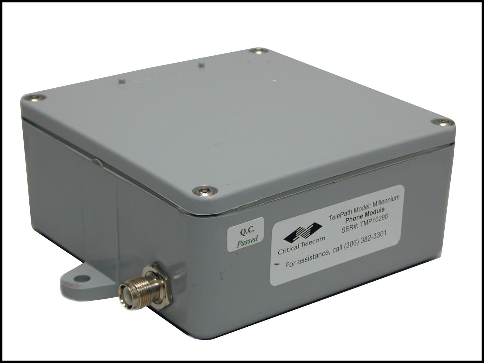
Click to zoom
Application Details
- Equipment Class
- DSS - Part 15 Spread Spectrum Transmitter
- Date of Grant
- Jun 28, 2001
- Application Purpose
- Original Equipment
- Date of Application
- May 28, 2001
- Equipment Note
- TELEPATH MILLENNIUM 2.4
- Frequency Range
- 2412.19200000 - 2472.10000000
- Company
- Critical Telecom Corp
- Country
- Canada
Documents & Files
Document Text
Text extracted from the exhibit documents filed with the FCC. Open a document above to read the original.
Users Manual
TelePATH 2.4GHz North Wireless Phone Link USER MANUAL Rev1.0 16 Mar 01 Copyright Critical Telecom Corp. 2000, 1999 Table of Contents 1)Overview....................................................................................................................2 2)Description and Features...........................................................................................2 3)Installation..................................................................................................................2 A)TOOLS Required..............................................................................................................2 B)Line module and Antenna.................................................................................................2 i)Mounting module.........................................................................................................................2 ii)Mounting Antenna.......................................................................................................................2 iii)Antenna Connection..................................................................................................................3 iv)Tip and Ring Connection............................................................................................................3 v)Power and Ground Connections.................................................................................................3 vi)Channel Selection......................................................................................................................3 C)Phone module and Antenna..............................................................................................3 i)Mounting module.........................................................................................................................3 ii)Mounting Antenna.......................................................................................................................3 iii)Antenna Connection..................................................................................................................3 iv)Tip and Ring Connection............................................................................................................3 v)Power and Ground Connections.................................................................................................4 vi)Channel Selection......................................................................................................................4 D)System Registration..........................................................................................................4 i)How can I tell that registering is needed?.....................................................................................4 ii)What should I DO?......................................................................................................................4 iii)How do I know it WORKED?......................................................................................................4 E)Ganged Multiple Line Installations.....................................................................................4 i)Registration.................................................................................................................................4 ii)Burst-sync Connections...............................................................................................................4 iii)Channel Selection......................................................................................................................5 F)Craft Interface...................................................................................................................5 4)Service Information....................................................................................................5 5)Specifications.............................................................................................................6 6)Limited Warranty........................................................................................................7 7)Customer Information.................................................................................................7 A)Analogue Device Warnings...............................................................................................7 B)Industry Canada Warnings................................................................................................7 C)Radio Interference Statement...........................................................................................8 Rev 1.0 TelePATH 2.4GHz North2 1) OVERVIEW Thank you for purchasing a TelePATH North digital wireless link from Critical Telecom. Your new TelePATH North is a carefully engineered, high-quality, durable product. It is designed to deliver the quality and performance you expect from telecommunications equipment. The TelePATH North digital wireless link is a cost effective solution for point-to-point voice and data communication. The system provides a reliable toll-quality wireless connection between a public telephone and the wire connection back to the central office. The TelePATH North may be used for both temporary and permanent installations where circumstances make conventionally wired installations impractical. 2) DESCRIPTION AND FEATURES The TelePATH North system consists of two modules, two antennas, and two coaxial cables. Once installed, the components provide a transparent wireless link between a phone and the central office. The “Line module” connects to the central office line. The “Phone module” connects to the phone. Phone and Line modules are similar in appearance but each is clearly labelled to avoid confusion. The TelePATH North has been specifically designed for use with payphones and supports all of their functions. The dimensions of TelePATH North are shown in figure #5. The TelePATH Millennium system may be used only with approved antennas (see the…
Text truncated - open the document above for the full version.
Users Manual
T 023-MS-OM-A3 IRF24085DS-02 T 023-MS-OM-A3 IRF24096DS-02 T 024-MS-OM-A3 IRF24192DS-02 T 010-MS-OM-A3 IRF24250DS-02 2400-2483.5 MHz RF Module InnoMedia Technology Inc. Science-Based Industrial Park, Hsinchu, Taiwan, R.O.C. TEL : +886-3-5641299 FAX : +886-3-5641589 Oct. 04, 1999 1 1 InnoMedia IRF24XXXDS 2400-2483.5 MHz RF Module ------------------------------------------------------------------------------------------------------------------------------------------ INTRODUCTION InnoMedia IRF24XXXDS RF Module is a radio transceiver that provides all of the baseband-to- RF and RF-to-baseband signal conversion functions needed for 2400-2483.5 MHz digital communication. It can accompany the ALFA AIC9001 Spread Spectrum Transceiver integrated circuit to support either digital voice or data communication, in both full-duplex and half-duplex operations. The IRF24XXXDS are high performance, compact size and low power consumption make it ideal for portable, battery-powered wireless products such as digital cordless phone and wireless modem. It also can meet FCC part requirements to let your wireless products get FCC approval easily. Figure 1 and 2 show the typical system applications for cordless phone and wireless modem. PC (DTE) RS-232 Driver ALFA AIC9001 SST ASIC InnoMedia IRF9085DS RF module Microprocessor Master Oscillator Figure 1. Block diagram of Wireless modem Note : MO = Master Oscillator 2 2 FEATURES • Designed for 2400-2483.5 Mhz wireless communication systems. • Time Division Duplexing ( TDD ). • GMSK Modulation/Demodulation. • Single conversion receiver. • Conforms to FCC part 15 requirements. • Power management for supply current minimization. • Low material cost. • Two tuning points only. • Provides 33/29/16/13 non-overlapping channels with AIC9001 SST chip. • Compact size (45mm x 60mm x 10 mm) RF MODULE BLOCK DIAGRAM The IRF24XXXDS RF Module is a complete combination of transmitter and receiver . The functional block diagram is shown in Figure 2. Figure 2. Block diagram of RF Module Antenna Drive AMP T/R Switch BPF Synthesizer Data In Clock Latch Enable Channel Select Lock Detect 16.384 MHz D/C IF AMPLNA BPFBPF Limiter AMP PDLPF Data Slicer Data Out RSSI U10 90 Degree RSSI T/R Control Demodulator 2.4-2.483GHz 2.4-2.483GHz BW=1.5MHz Fc=44MHz X2BPFPA Batt IN RF 4.5V IN Power Control RF Power PLL SW Loop Filter Gaussian Filter SUM VCO Tx::1200-1242MHz Rx::1220-1264MHz Buffer Amp. DIVIDER 3 3 A) TRANSMITTER The module employs a T/R switch to switch between transmit and receive in the time domain. The MODOUT spread baseband digital data signal is filtered and up-converted to RF by the GMSK modulator. Due to the following properties: constant envelope, compact spectrum, fast roll-off of higher-order sideband, and easy detection, GMSK is used herein. Then the PA output routes through the transmit/receive ( T/R ) switch and a ceramic band pass filter is used to remove out- band harmonics before exiting the module at the antenna port. B) RECEIVER From the antenna port, the RF signal passes through the ceramic bandpass and the T/R switch to remove the signals outside the 2400-2483.5 MHz band before entering the low noise amplifier ( LNA). It then is down-converted to IF signals and filtered by a very high selective SAW filter to reject the out-band spurious and interference. Before going to the Discriminator Demodulator, the IF signals is processed by a limiting amplifier with a gain over 70 dB to improve the noise performance. It finally passes through the LPF and Comparator to get the raw data information. The Receiving Signal Strength Indicator ( RSSI ) coming out of the limiter can be used as a power control reference for the baseband microprocessor ( uP ). C) VCO & SYNTHESIZER A Sigle frequency synthesizer (MB15E03SL by Fujitsu) is used together with single voltage controlled oscillator (VCO) to form a synthesized phase locked loop (PLL) for transmission and receiving channel selection. Channel selection is done by programming a control register in the MB15E03SL through a serial interface by a microcontroller. The PLL specification and related information is described in a later section. Detailed specifications for the MB15E03SL can be found in data books from Fujitsu. SPECIFICATIONS OF RF MODULE • Frequency Band :2400 to 2483.5 MHz • Channel Spacing :2.56/4.608/5.5 MHz • Non-overlapping channels:33/29/16/13 (with the AIC9001 SST chip ) • Frequency Stability +/- 30 ppm ( depends on input reference ) • Phase Noise :-90 dBc/Hz @ 100 KHz (depends on input reference ) • PLL Lock Up Time :< 300 us • Transmission Data Rate :1.536/3.072/4.0 Mbps • Power Output : 20+/-2 dBm/high power (with BATT IN >= 4.8V ) • Modulation :GMSK • Dynamic Range : -30 to -90 dBm @ BER < 10 e-3 for IRF24085DS -30 to –88 dBm @ BER < 10e-3 for IRF24096DS -30 to –87 dBm @ BER < 10e-3 for IRF24192DS -30 to –85 dBm @BER < 10e-3 for IRF24250DS • Emission :FCC part 15 compliance • Current Consumption :200 mA /TX (Typical) 70 mA /RX (Typical) 4 4 • T/R Access :TDD MECHANICAL & ENVIRONMENTAL • Module Dimensions : 45 mm x 60 mm x 10 mm ( including shield case ) • Operating Temperature :0°C to + 50°C • Storage Temperature :-30°C to + 70°C RECOMMENDED ANTENNA SPECIFICATION • Frequency Range :2400 to 2483.5 MHz • Frequency Center :2442 MHz • Gain :2 dBi • VSWR :2:1 RF-BASEBAND INTERFACE DESCRIPTIONS & ASSIGNMENTS The RF Module interface defined herein is the interface to the baseband portion and it is a 16-pin male connector (refer to appendix A). The pin-assignment and description of RF-to-BASEBAND interface is explained as follows and the pin-allocation diagram is depicted in appendix C : Pin# Pin Name Type Description 1BATT INInputDC power supply input ( min 4.4 V ) to provide the DC power of the power amplifiers. current consumption : 120 mA @ 5 V (Typical) 216.384/InputInput as the reference source of the synthesizer. 18.432/frequency stability: +/- 30 ppm 9.216/phase noise : < -110 dBc @ +/- 5 KHz 12MHzspurious : < -70 d…
Text truncated - open the document above for the full version.
Users Manual
TelePATH 2.4GHz North Wireless Phone Link INSTALLATION MANUAL Rev1.1 29 May 2001 Copyright Critical Telecom Corp. 2000, 1999 Table of Contents 1)Overview....................................................................................................................2 2)Description and Features...........................................................................................2 3)Installation..................................................................................................................2 A)TOOLS Required............................................................................................................2 B)Line module and Antenna...............................................................................................2 i)Mounting module..................................................................................................................2 ii)Mounting Antenna.................................................................................................................2 iii)Antenna Connection..............................................................................................................3 iv)Tip and Ring Connection.......................................................................................................3 v)Power and Ground Connections............................................................................................3 vi)Channel Selection.................................................................................................................3 C)Phone Module and Antenna............................................................................................3 i)Mounting Module..................................................................................................................3 ii)Mounting Antenna.................................................................................................................3 iii)Antenna Connection..............................................................................................................3 iv)Tip and Ring Connection.......................................................................................................4 v)Power and Ground Connections............................................................................................4 D)System Registration........................................................................................................4 i)How can I tell that the module needs registering?..................................................................4 E)Ganged Multiple Line Installations...................................................................................4 i)Registration..........................................................................................................................4 ii)Burst-sync Connections........................................................................................................4 iii)Channel Selection.................................................................................................................5 F)Craft Interface.................................................................................................................5 4)Service Information....................................................................................................5 5)Specifications.............................................................................................................6 6)Limited Warranty........................................................................................................7 7)Customer Information.................................................................................................7 A)Analogue Device Warnings.............................................................................................7 B)Industry Canada Warnings..............................................................................................8 C)Radio Interference Statement..........................................................................................8 Rev 1.1 TelePATH 2.4GHz North2 1) OVERVIEW Thank you for purchasing a TelePATH North digital wireless link from Critical Telecom. Your new TelePATH North is a carefully engineered, high-quality, durable product. It is designed to deliver the quality and performance you expect from telecommunications equipment. The TelePATH North digital wireless link is a cost effective solution for point-to-point voice and data communication. The system provides a reliable wireless connection between a telephone and the wire connection back to the Central Office. The TelePATH North may be used for both temporary and permanent installations where circumstances make conventionally wired installations impractical. 2) DESCRIPTION AND FEATURES The TelePATH North system consists of two modules, two antennas, and two coaxial cables. Once installed, the components provide a transparent wireless link between a phone and the Central Office. The “line module” connects to the Central Office line. The “phone module” connects to the telephone. Phone and line modules are similar in appearance but each is clearly labelled to avoid confusion. The TelePATH North system has been specifically designed for use with telephones including payphones and supports all of their functions. The dimensions of TelePATH North are shown in Figure 4. The TelePATH system may be used only with approved antennas (see the Specifications section for a list of approved antennas). Either module may be used with any of the three antennas. In Canada, the TelePATH system must be professionally installed and only channels 0, 1, 2 are to be used in compliance with Industry Canada’s Radio Standards Specification RSS-210, Issue 2, Rev.1. Critical Telecom accepts no responsibility or liability should the system be installed in violation of IC Radio Standards Specification RSS-210, Issue 2, Rev.1, when used in Canada. 3) INSTALLATIO…
Text truncated - open the document above for the full version.
Attestation Statements
116 – 116 Research Drive, Saskatoon, Saskatchewan, Canada S7N 3R3 Tel: 306 382 3301 www.criticaltelecom.com [email protected] Fax: 306 978 3301 REQUEST FOR NONDISCLOSURE OF INFORM ATION IN CERTIFICATION APPLICAT IONS 1. Identification of information to be withheld from the public • Schematics (“2.4GHz Line Schematic Rev1.1.pdf” and “2.4GHz Phone Schematic Rev1.0.pdf”) – 3 pages each • Parts Lists (“Parts List 2.4GHz Line PWA Rev1.0.pdf” – and “Parts List 2.4GHz Phone PWA Rev1.0.pdf”) – Line 6 pages – Phone 7 pages • System Description (“Description 2.4GHz Rev1.1.pdf”) – 9 pages 2. Applications in which the information appears • FCC Rules part 15 subpart C (FCC ID: NE9TM2001) • FCC Rules part 68 3. Degree to which the information is commercial in nature, or contains trade secrets All of the identified information is confidential and includes trade secrets. It is not publicly known how our product performs its tasks. The submitted schematics, parts lists, and technical description documentation reveal intellectual property that is proprietary and should not be released. 4. Degree to which the information concerns a product or service that is subject to competition All of the identified information concerns a system that is marketed in the highly competitive wireless telecommunications market. 5. How disclosure of the information will cause competitive harm Disclosure of any of the identified information could enable competitors to benefit improperly from our hard-won intellectual property and harm our competitive advantage. 6. Measures taken to keep the information confidential Confidentiality agreements have been signed with personnel who have access to this information. The identified information is stored in a secure area that is not accessible to wide-area-networks. 7. Statement of information privacy None of the identified information is available to the public, and no previous disclosures have been made to third parties. 8. Period of time over which protection is requested Projections show that the marketable life-cycle of this system is 7 years; therefore, we request confidentiality protection for a period of at least 7 years. 9. Additional information that may help the FCC in determining whether to grant the request A very large investment of time and money has been made in the development of this proprietary system. Disclosure of any of the identified information would undermine the competitive process. Signed ____ __________________________ Printed Jeff Hehn Title Product Engineer
ID Label/Location Info
Regulatory Label Bottom of Enclosure This devices complies with Part 15 of the FCC Rules. Operation is subject to the following two rules: (1) This device may not cause harmful interference, and (2) This device must accept any interference received, including interference that may cause undesired operation. Made in Canada Critical Control Corp. Complies with Part 68, FCC Rules IC REN: 0.4 CANADA: 27641031875A Model No.: TelePath Millennium Registration No.: ?????????? FCC REN: 0.4B FCC ID: NE9TM2000 This devices complies with Part 15 of the FCC Rules. Operation is subject to the following two rules: (1) This device may not cause harmful interference, and (2) This device must accept any interference received, including interference that may cause undesired operation. Made in Canada Critical Control Corp. Complies with Part 68, FCC Rules IC REN: 0.4 CANADA: 27641031875A Model No.: TelePath Millennium 2.4 Registration No.: ?????????? FCC REN: 0.4B FCC ID: NE9TM2001 1.40 " 1.60" Font: Arial, 5.5pt & 4.7pt Scale: 2:1
RF Exposure Info
2.4GHz Telepath MPE Calculation The following calculation is provided to determine the minimum distance that a person can be from the antenna so as not to exceed the Maximum Permissible Exposure (MPE) regulation of FCC 1.1310. Table 1(B) - General Population/Uncontrolled Exposure gives the MPE limit in the 2.4GHz MHz ISM band as follows: MPE = 1.0 where MPE is in units of [mW/cm 2 ] regardless of frequency (1) The power output of our radio device was measured and found to be always less than 100 mW. (2) Antenna gain is 8 dBi. (3) The antenna gain (3) can be applied to the maximum output power (2) to yield an effective isotropic radiated output power as follows: Piso = 100 mW * 10 (8/10) (4) Piso = 631mW (5) The minimum distance permissible can be computed based on the surface area of the isotropic sphere: Aiso = 4 * pi * r 2 where Aiso is the area [cm 2 ] and r is the radius of the sphere [cm] (6) MPE * Aiso = Piso (7) r = (Piso / (MPE * 4 * pi)) (1/2) (8) r = (631 [mW] / (1.0 [mW/cm 2 ] * 4 * pi)) (1/2) (9) r = 7 cm or 2-3/4 in (10) The following statement is included in the Installation Manual: “To comply with FCC requirements for RF exposure, antennas must be installed such that no persons will be closer than 20cm (8”) from any part of the antenna while operational.” Jeff Hehn May 25 th , 2001
Test Report
Master: PT15CDST Date: February 25, 2001 Test Report:1W03763 Applicant:Critical Telecom 116 Research Drive, Suite 116 Saskatoon, Saskatchewan S7N 3R3 Equipment Under Test:Telepath Millennium 2.4 (EUT) FCC ID:NE9TM2001 In Accordance With:FCC Part 15, Subpart C Direct Sequence Transmitters 902 - 928 MHz Tested By:Nemko Canada Inc. (Formerly KTL Ottawa Inc.) 3325 River Road, R.R. 5 Ottawa, Ontario K1V 1H2 Authorized By: R. Grant, Wireless Group Manager Date: Total Number of Pages:32 Nemko Canada Inc. FCC PART 15, SUBPART C DIRECT SEQUENCE TRANSMITTERS PROJECT NO.: 1W03763 EQUIPMENT: Telepath Millennium 2.4 FCC ID: NE9TM2001 Page 2 of 29 Table Of Contents Section 1. Summary Of Test Results......................................................................................... 3 Section 2. General Equipment Specification ........................................................................... 5 Section 3. Occupied Bandwidth................................................................................................ 8 Section 4. Peak Power Output ................................................................................................ 12 Section 5. Spurious Emissions (Antenna Conducted)........................................................... 13 Section 6. Spurious Emissions (Radiated).............................................................................. 17 Section 7. Transmitter Power Density ................................................................................... 23 Section 8. Processing Gain ......................................................................................................27 Section 9. Test Equipment List ............................................................................................... 29 Annex A Block Diagrams...................................................................................................... A1 Nemko Canada Inc. FCC PART 15, SUBPART C DIRECT SEQUENCE TRANSMITTERS PROJECT NO.: 1W03763 EQUIPMENT: Telepath Millennium 2.4 FCC ID: NE9TM2001 Page 3 of 29 Section 1.Summary Of Test Results General All measurements are traceable to national standards. These tests were conducted on a sample of the equipment for the purpose of demonstrating compliance with FCC Part 15, Subpart C, Paragraph 15.247 for Direct Sequence Spread Spectrum devices. New SubmissionProduction Unit Class II Permissive ChangePre-Production Unit THIS TEST REPORT RELATES ONLY TO THE ITEM(S) TESTED. THE FOLLOWING DEVIATIONS FROM, ADDITIONS TO, OR EXCLUSIONS FROM THE TEST SPECIFICATIONS HAVE BEEN MADE. See “ Summary of Test Data”. NVLAP LAB CODE: 100351-0 TESTED BY: _____________________________________ DATE: ___________________ Wayne Clarke, Wireless Technologist Nemko Canada Inc. authorizes the above named company to reproduce this report provided it is reproduced in its entirety and for use by the company’s employees only. Any us e whic h a third p a rty ma k e s o f this re p o rt, o r a ny re lia nc e o n o r d e c is io ns to b e ma d e b a s e d o n it, a re the re s p o ns ib ility of such third parties. Nemko Canada Inc. accepts no responsibility fo r d a ma ge s , if a ny, s uffe re d b y a ny third p a rty a s a re s ult o f d e c is io ns ma d e o r a c tio ns b a s e d o n this re p o rt. This report applies only to the items tested. Nemko Canada Inc. FCC PART 15, SUBPART C DIRECT SEQUENCE TRANSMITTERS PROJECT NO.: 1W03763 EQUIPMENT: Telepath Millennium 2.4 FCC ID: NE9TM2001 Page 4 of 29 Summary Of Test Data Name Of TestPara. No.Result Powerline Conducted Emissions15.207 (a)N/A Occupied Bandwidth15.247 (a)(2)Complies Peak Power Output15.247 (b)Complies Spurious Emissions (Antenna Conducted)15.247 (c)Complies Spurious Emissions (Radiated)15.247 (c)Complies Transmitter Power Density15.247 (d)Complies Processing Gain15.247 (e)Complies Footnotes For N/A’s:The EUT is powered by 12VDC. Test Conditions: IndoorTemperature: 22 °C Humidity:35 % OutdoorTemperature: 12 °C Humidity:87 % Nemko Canada Inc. FCC PART 15, SUBPART C DIRECT SEQUENCE TRANSMITTERS PROJECT NO.: 1W03763 EQUIPMENT: Telepath Millennium 2.4 FCC ID: NE9TM2001 Page 5 of 29 Section 2.General Equipment Specification Manufacturer:Critical Telecom Model No.:Millennium Serial No.:TML10298 Date Received In Laboratory:April 18, 2001 Nemko Identification No.:Item #1 Transmitter Power Input:10-36VDC Frequency Range:2412.192 to 2472.10MHz Tunable Bands:One 6 dB Bandwidth:1.99MHz Type of ModulationGMSK Data Rate:14.4KBPS Emissions Designator:1M99F1W Output Impedance:50 ohm RF Power Output (Rated):+18dBm Power Output Adjustment Capability:None Duty Cycle:= ms OnTime 100 log20 = 20log 100 17.411 x = 20log 0.4587 = -6.8dB Nemko Canada Inc. FCC PART 15, SUBPART C DIRECT SEQUENCE TRANSMITTERS PROJECT NO.: 1W03763 EQUIPMENT: Telepath Millennium 2.4 FCC ID: NE9TM2001 Page 6 of 29 Nemko Canada Inc. FCC PART 15, SUBPART C DIRECT SEQUENCE TRANSMITTERS PROJECT NO.: 1W03763 EQUIPMENT: Telepath Millennium 2.4 FCC ID: NE9TM2001 Page 7 of 29 Nemko Canada Inc. FCC PART 15, SUBPART C DIRECT SEQUENCE TRANSMITTERS PROJECT NO.: 1W03763 EQUIPMENT: Telepath Millennium 2.4 FCC ID: NE9TM2001 Page 8 of 29 Section 3.Occupied Bandwidth Para. No.: 15.247(a)(2) Test Performed By: Wayne ClarkeDate of Test: April 19, 2001 Test Results:Complies. The 6 dB bandwidth is 1.99MHz. See attached graphs. Measurement Data:See attached graphs. Nemko Canada Inc. FCC PART 15, SUBPART C DIRECT SEQUENCE TRANSMITTERS PROJECT NO.: 1W03763 EQUIPMENT: Telepath Millennium 2.4 FCC ID: NE9TM2001 Page 9 of 29 Nemko Canada Inc. FCC PART 15, SUBPART C DIRECT SEQUENCE TRANSMITTERS PROJECT NO.: 1W03763 EQUIPMENT: Telepath Millennium 2.4 FCC ID: NE9TM2001 Page 10 of 29 Nemko Canada Inc. FCC PART 15, SUBPART C DIRECT SEQUENCE TRANSMITTERS PROJECT NO.: 1W03763 EQUIPMENT: Telepath Millennium 2.4 FCC ID: NE9TM2001 Page 11 of 29 Nemko Canada Inc. FCC PART 15, SUBPART C DIRECT SEQUENCE TRANSMITTERS PROJECT NO.: 1W03763 EQUIPMENT: …
Text truncated - open the document above for the full version.
Test Report
Test Data for J/S Measurement @ BER=1.0E-3 Delta Freq. (MHz) J/S (dB) Signal (dBm) Jo (dBm) J (dBm) 2440.99 8.58 -18.20 1.1 -9.62 2441.04 5.38 -18.20 -2.1 -12.82 2441.09 3.38 -18.20 -4.1 -14.82 2441.14 1.78 -18.20 -5.7 -16.42 2441.19 0.58 -18.20 -6.9 -17.62 2441.24 -0.22 -18.20 -7.7 -18.42 2441.29 -0.62 -18.20 -8.1 -18.82 2441.34 -1.42 -18.20 -8.9 -19.62 2441.39 -1.92 -18.20 -9.4 -20.12 2441.44 -2.32 -18.20 -9.8 -20.52 2441.49 -2.82 -18.20 -10.3 -21.02 2441.54 -2.92 -18.20 -10.4 -21.12 2441.59 -3.42 -18.20 -10.9 -21.62 2441.64 -3.62 -18.20 -11.1 -21.82 2441.69 -3.62 -18.20 -11.1 -21.82 2441.74 -3.62 -18.20 -11.1 -21.82 2441.79 -2.32 -18.20 -9.8 -20.52 2441.84 -0.92 -18.20 -8.4 -19.12 2441.89 -0.72 -18.20 -8.2 -18.92 2441.94 -0.82 -18.20 -8.3 -19.02 2441.99 -1.12 -18.20 -8.6 -19.32 2442.04 -1.52 -18.20 -9.0 -19.72 2442.09 -1.72 -18.20 -9.2 -19.92 2442.14 -1.72 -18.20 -9.2 -19.92 2442.19 -1.72 -18.20 -9.2 -19.92 2442.24 -1.42 -18.20 -8.9 -19.62 2442.29 -1.22 -18.20 -8.7 -19.42 2442.34 -1.22 -18.20 -8.7 -19.42 2442.39 -1.22 -18.20 -8.7 -19.42 2442.44 -1.62 -18.20 -9.1 -19.82 2442.49 -2.12 -18.20 -9.6 -…
Text truncated - open the document above for the full version.
Contact Information
Applicant
Michael Lockerbie(Project Engineer)
Technical Contact
Non-Technical Contact
NEMKO CANADA INC.RUBY C DULMAGE
[email protected]800-563-6336
Test Firm
Nemko Canada Inc.Stuart Beck
Technical Specifications
| # | Rule Parts | Frequency Range | Power Output |
|---|---|---|---|
| 1 | 15C | 2.41 GHz - 2.47 GHz | 74.00 mW |
Other Applications from Critical Telecom Corp
NE9TM2000
Dec 13, 2000TelePath Millenium System
Equipment Class
DSS - Part 15 Spread Spectrum TransmitterNE9FCR10096
Oct 01, 1997R/C Receiver
Equipment Class
CYY - Communications Receiver used w/Pt 15 TransmitterNE9FCT10097
Oct 01, 1997R/C Transmitter
Equipment Class
DSC - Part 15 Security/Remote Control TransmitterNE9PCC11089
Sep 22, 1997Vehicle Security System Transmitter
Equipment Class
DSC - Part 15 Security/Remote Control Transmitter