NFBLAB110Load Moment Indicator
Cranesmart Systems Inc.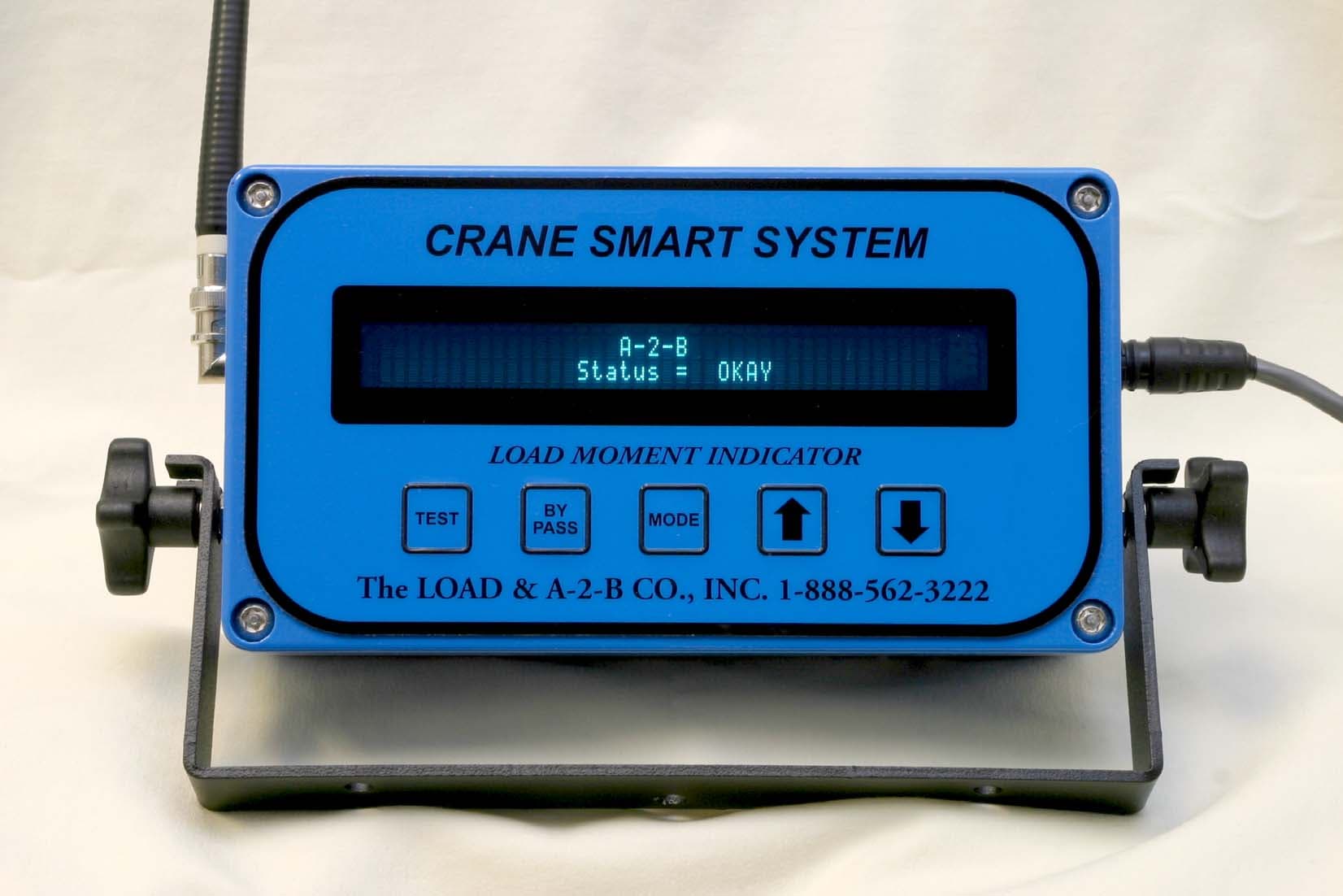
Click to zoom
Application Details
- Equipment Class
- CYY - Communications Receiver used w/Pt 15 Transmitter
- Date of Grant
- Jun 28, 2004
- Application Purpose
- Original Equipment
- Date of Application
- Apr 29, 2003
- Equipment Note
- Load Moment Indicator
- Frequency Range
- 49.83000000 - 49.89000000
- Company
- Cranesmart Systems Inc.
- Country
- Canada
Documents & Files
Document Text
Text extracted from the exhibit documents filed with the FCC. Open a document above to read the original.
Users Manual
1 The LOAD & A-2-B Company Inc. Cranesmart™ LMI System Installation and Operating Manual “Congratulations! You have invested in the industry’s leading technology in crane safety equipment. Thank you very much for your business” The contents of this manual must be read and thoroughly understood before operating the crane with this equipment installed For sales, service or assistance: 1-888-562-3222 / (780) 437-2986 www.cranesmart.com Please have the serial number of your system handy before calling to purchase batteries or to ask for technical assistance. You can find the serial number on either the receiver panel or the transmitters. Please see page 54 for FCC Compliance Revision March 18, 2003 – 1.09A 2 Foreword – Installation guidelines, tools required 4 Section One Contents 5 – LOAD CELL installation 6-8 – ANTI-2-BLOCK installation and explanation 9-13 – ANGLE SENSOR installation 14 – RECEIVER/DISPLAY PANEL installation 15 – ALARM HUB installation and explanation 16 – SHUT OFF configuration 17 – ANTENNA installation 17 Section Two Contents 19 – Cranesmart™ Load Moment Indicator panel functions 20 – PANEL BUTTON definitions and use 20 – FIRST TIME system start up, LOAD CHART information 21 – Correct WINCH in use selection 21 – Correct CHART in use selection 21 – Correct PARTS-OF-LINE selection 22 – PRIMARY OPERATING DISPLAY explained 22 – SECONDARY OPERATING DISPLAY explained 23 Section Three Contents 25 – LOAD CELL calibration – KNOWN WEIGHTS explained 26-29 – ANGLE SENSOR SIDE selection 30-32 – ANGLE ZERO calibration 33-35 – ANGLE SENSOR SELECTION for use (main or jib) 36-38 Table of Contents 1 3 Table of Contents 2 Section Four Contents 39 – Selecting WINCH LINE in use 40 – Setting LOAD MINIMUM alarms 41 – Setting LOAD MAXIMUM alarms 42 – To ENABLE TARE OUT function 43-44 – To DISABLE TARE OUT function 44 – Setting ANGLE MINIMUM alarms 45 – Setting ANGLE MAXIMUM alarms 46 – Setting RADIUS MINIMUM alarms 47 – Setting RADIUS MAXIMUM alarms 48 – Setting TIP HEIGHT MINIMUM alarms 49 – Setting TIP HEIGHT MAXIMUM alarms 50 Section Five Contents – Bypass key instructions 51 – Trouble-shooting for panel, battery and system lights 52 – No communication between transmitters and panel 53 – System technical component specifications 54 – Warranty 54 Warranty The Load & A-2-B Company Inc. warrants to the purchaser of each new Cranesmart™ System that any part thereof which proves to be defective in material or workmanship within two (2) years from date of delivery will be repaired or replaced at no charge, if the system is returned to us in Edmonton, Alberta with all freight charges prepaid. If a performance problem should occur, contact our office in Edmonton, Alberta at 1-888-562-3222. This warranty does not cover defects resulting from accident, alteration, improper use, or failure of the purchaser to follow normal operating procedures as outlined in this instruction manual. PLEASE NOTE: OPENING THE BLUE RECEIVER PANEL VOIDS WARRANTY. THIS WARRANTY IS IN LIEU OF ANY WARRANTY OR MERCHANTABILITY AND OF ALL OTHER WARRANTIES, EXPRESSED OR IMPLIED, ALL OF WHICH ARE HEREBY EXCLUDED. The Load & A-2-B Company Inc. shall in no event be liable for any special, indirect, or consequential damages whatsoever and neither assumes nor authorizes any person to assume for it any other obligation or liability. 4 THIS LOAD MOMENT INDICATOR ***DOES NOT*** REQUIRE CALIBRATION. IT IS CALIBRATED AT THE FACTORY. ATTENTION DO NOT CONSIDER THIS SYSTEM A SUBSTITUTE FOR GOOD JUDGMENT, EXPERIENCE AND ACCEPTED, SAFE CRANE OPERATING PRACTICES. ———————————————————— THE CONTENTS OF THIS MANUAL MUST BE READ AND THOROUGHLY UNDERSTOOD BEFORE OPERATING THE CRANE. ——————————————————— THIS SYSTEM UTILIZES A SERIES OF ELECTRICAL AND MECHANICAL COMPONENTS AND CANNOT BE 100% FAIL SAFE. Installation guidelines Read all of these instructions completely prior to beginning D 12 volt application only. Check voltage as a step down converter will be required if voltage is other than 12VDC D Mount the load cells, anti-2-block switches and or angle transducers first D Plan the installation D Have the necessary tools available D Mount the display panel second D Test the system Tools required D Man basket – to reach the boom, rooster sheave and or jib tip D Pliers for removing and bending cotter pins D Electric drill with various drill bits D Welder for attaching weld plated to boom/jib tips D Wire crimping tools – for the display power and ground connections D Screw drivers and or socket set D Clear silicone 5 Section One This section provides information for placement and installation of the following components: DLoad cells DAnti-2-block switches DAngle sensors DReceiver/display panel DAlarm Hub panel DAntennae 6 Load cell installation and placement guide for load cell links Figure ‘A’ - Pin the BLUE load cell between the wire rope socket (becket) and the dead end on the main boom of the crane. >MAIN< Figure ‘B’- Pin the YELLOW load cell between the wire rope socket (becket) and the headache ball on the auxiliary sheave (rooster) on the cranes boom tip. >AUX 1< (Note: for two line load systems only) Figure ‘C’- Pin the ORANGE load cell between the wire rope socket (becket) and the headache ball on the jib extension. >AUX 2< (Note: for three line load systems only) Auxiliary 2 ORANGE Load cell placement Auxiliary 1 YELLOW Load cell placement Rooster sheave whip/fast line MAIN BLUE Load cell placement DEAD END Blue receiver panel mounted in cab JIB EXTENSION Figure ‘A’ Figure ‘B’ Figure ‘C’ Headache balls Hook block Becket or wire rope socket External mount antenna placed on roof of operator cab 7 Male – Female - Load cell link Placement on BOOM TIP DEAD END Even part-of-line operation For even parts-of-line, the load cell link is simply pinned between the wire rope (wedge) socket and the dead end on the boom tip as illustrated. Male – Female - Load cell link Placement on HEADACHE BALL Single part-of-line For single part-of-line, the load cell li…
Text truncated - open the document above for the full version.
Cover Letter(s)
June 28, 2004 Re: FCC ID NFBLAB110 Applicant: Load & A-2-B Company Inc, The Correspondence Reference Number: 26860 731 Confirmation Number: EA485420 To Whom It May Concern; We are submitting our LMI Display Panel for Part 15 acceptance. We request that all schematics, circuit diagrams, and circuit descriptions remain confidential in order to prevent this information from being used by our competitors. Regards; Mike Nachai, M.Sc, P.Eng. The Load & A2B Company Inc.
Test Report
This report shall not be reproduced, except in full, without prior written approval of MPB Technologies Inc. Test Report Prepared By: Electronics Test Centre 27 East Lake Hill Airdrie, Alberta Canada T2B 2B7 [email protected] phone: (403) 912-0037 fax: (403) 912-0083 MPBT Report No.: t11e2736Rev: 1Date: 26 February 2003 Report for Emissions Testing of the Crane Smart System Display In accordance with FCC Part 15, Subpart B (2000). Test Personnel:David Raynes Prepared for:The Load & A2B Company Inc. 4908 - 97 Street Edmonton, Alberta Canada T6E 5S1 _________________________ Client Acceptance Authorized Signatory Senior EMC Technologist Electronics Test Centre (Airdrie) Authorized Signatory Test Sample: Crane Smart System Display FCC Part 15 Subpart B (2000) Report No.:t11e2736 rev. 1 This report shall not be reproduced, except in full, without prior written approval of MPB Technologies Inc. TABLE OF CONTENTS 1.0INTRODUCTION 1.1Scope 1.2Applicant 1.3Applicability 1.4Test Sample Description 1.5General Test Conditions and Assumptions 1.6Scope of Testing 1.6.1 Variations in Test Methods 1.6.2 Emissions Measurements 1.6.3 Test Sample Modifications 2.0ABBREVIATIONS 3.0MEASUREMENT UNCERTAINTY 4.0TEST CONCLUSION 4.1 Conducted Emissions 4.2 Radiated Emissions 5.0TEST FACILITY 5.1 Location 5.2 Grounding Plan 5.3Power 5.4 Emissions Profile 5.5 Test Configuration 5.5.1Tabletop Equipment 5.5.2Rack Mount 6.0TEST EQUIPMENT 6.1Radiated Emissions 6.2 Conducted Emissions 6.3Calibration APPENDIX A:Test Sample Description:Crane Smart System Display Test Sample: Crane Smart System Display FCC Part 15 Subpart B (2000) Report No.:t11e2736 rev. 1 This report shall not be reproduced, except in full, without prior written approval of MPB Technologies Inc. 1.0 INTRODUCTION 1.1SCOPE The purpose of this report is to present the findings and results of compliance testing performed in accordance with FCC Part 15, Subpart B (2000). 1.2APPLICANT This test report has been prepared for The Load & A2B Company Inc., located in Calgary, Alberta, Canada. 1.3APPLICABILITY All test procedures, limits, and results defined in this document apply to the The Load & A2B Company Inc. Crane Smart System Display unit, referred to herein as the Equipment Under Test (EUT). The results contained in this report relate only to the item tested. This report does not imply product endorsement by AALA, NVLAP, or the Canadian or US governments. 1.4TEST SAMPLE DESCRIPTION The test sample provided for testing was a Crane Smart System Display: Product Type:display panel, operational monitor Model Number:Crane Smart Display Serial Number:n/a Cables:power Power Requirements: nominal 12 VDC Peripheral Equipment: sensors for boom position and load More detailed information is provided by The Load & A2B Company Inc. in Appendix A. 1.5GENERAL TEST CONDITIONS AND ASSUMPTIONS The EUT was set up and exercised using the configurations, modes of operation and arrangements defined in this report only. All inputs and outputs to and from other equipment associated with the EUT were adequately simulated. Where relevant, the EUT was only tested using the monitoring methods and test criteria defined in this report. Test Sample: Crane Smart System Display FCC Part 15 Subpart B (2000) Report No.:t11e2736 rev. 1 This report shall not be reproduced, except in full, without prior written approval of MPB Technologies Inc. 1.6SCOPE OF TESTING Testing was performed in accordance with FCC Part 15, Subpart B (2000). 1.6.1VARIATIONS IN TEST METHODS There were no variations from the test procedures outlined above. 1.6.2MARGINAL EMISSIONS MEASUREMENTS As noted in Section 4, some emissions were measured to be within -6 dB of the specified limit. 1.6.3TEST SAMPLE MODIFICATIONS There were no equipment modifications during test performance. 2.0 ABBREVIATIONS AP-Average Peak CE-Conducted Emissions E -Field - Electric Field H-Field - Magnetic Field N/T-Not Tested N/A-Not Applicable PK-Peak QP-Quasi Peak RE-Radiated Emissions 3.0 MEASUREMENT UNCERTAINTY For Radiated E-Field Emissions and Conducted Emissions, the uncertainties in the measurements were calculated using the methods outlined in the NAMAS document, NIS81: May 1984. Frequency= ± 1 kHz Amplitude (RE)= ± 4.01 dB Amplitude (CE)= ± 3.25 dB Test Sample: Crane Smart System Display FCC Part 15 Subpart B (2000) Report No.:t11e2736 rev. 1 This report shall not be reproduced, except in full, without prior written approval of MPB Technologies Inc. 4.0 TEST CONCLUSION The EUT was subjected to the following tests. Compliance status is indicated as PASS or FAIL. The following table summarizes the test results in terms of the specification and class or level applied, the unique test sample identification, the EUT modification state, and configuration as applicable. TEST CASE TEST TYPESPECIFICATIONCLASS/ LEVEL TEST SAMPLE MOD. STATE CONFIGURATIONRESULT §4.1Conducted Emissions FCC Part 15 Subpart B n/aCrane Smart System Display niln/a N/A §4.2Radiated Emissions FCC Part 15 Subpart B ACrane Smart System Display nilSee § 1.6.3 PASS STATEMENT OF COMPLIANCE The client equipment referred to in this report was found to comply with the requirements as stated above. Test Sample: Crane Smart System Display FCC Part 15 Subpart B (2000) Report No.:t11e2736 rev. 1 This report shall not be reproduced, except in full, without prior written approval of MPB Technologies Inc. 4.1CONDUCTED EMISSIONS The was not tested for Conducted Emissions. This is a DC powered device. The power source is provided by the end user, not The Load & A2B Company Inc. There is no direct connection to the AC mains. Test Lab: Electronics Test Centre (Airdrie) Test Personnel: David Raynes Test Date: n/a Product: Crane Smart System Display Test Result, Crane Smart System Display: Not Applicable 4.2RADIATED EMISSIONS Test Lab: MPB Technologies Inc. Airdrie Test Personnel: David Raynes Test Date: 18 February 2003 Product: Crane Smart System Display Test Result, Crane Smart System…
Text truncated - open the document above for the full version.
Contact Information
Applicant
Mike Nachai(Engineer)
Technical Contact
The Load & A-2-B Company Inc.Mike Nachai
[email protected](888) 562-3222
4908 - 97th Street · Edmonton · Canada
Non-Technical Contact
The Load & A-2-B Company Inc.Tom Bilodeau
(888) 562-3222
Test Firm
Electronics Test CentreV Mediboina
Technical Specifications
| # | Rule Parts | Frequency Range | Power Output |
|---|---|---|---|
| 1 | 15B | 49.83 MHz - 49.89 MHz | - |
Other Applications from Cranesmart Systems Inc.
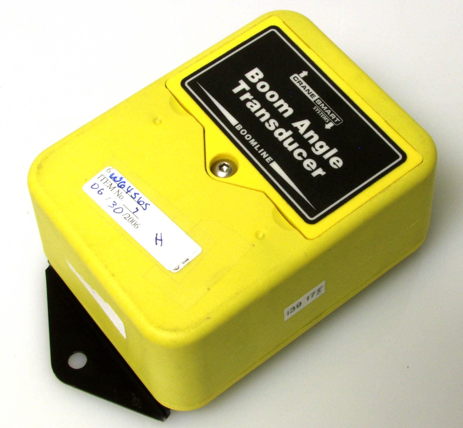
NFBLAB124
Aug 27, 2006Wireless Boom Angle Transducer
Equipment Class
DXX - Part 15 Low Power Communication Device Transmitter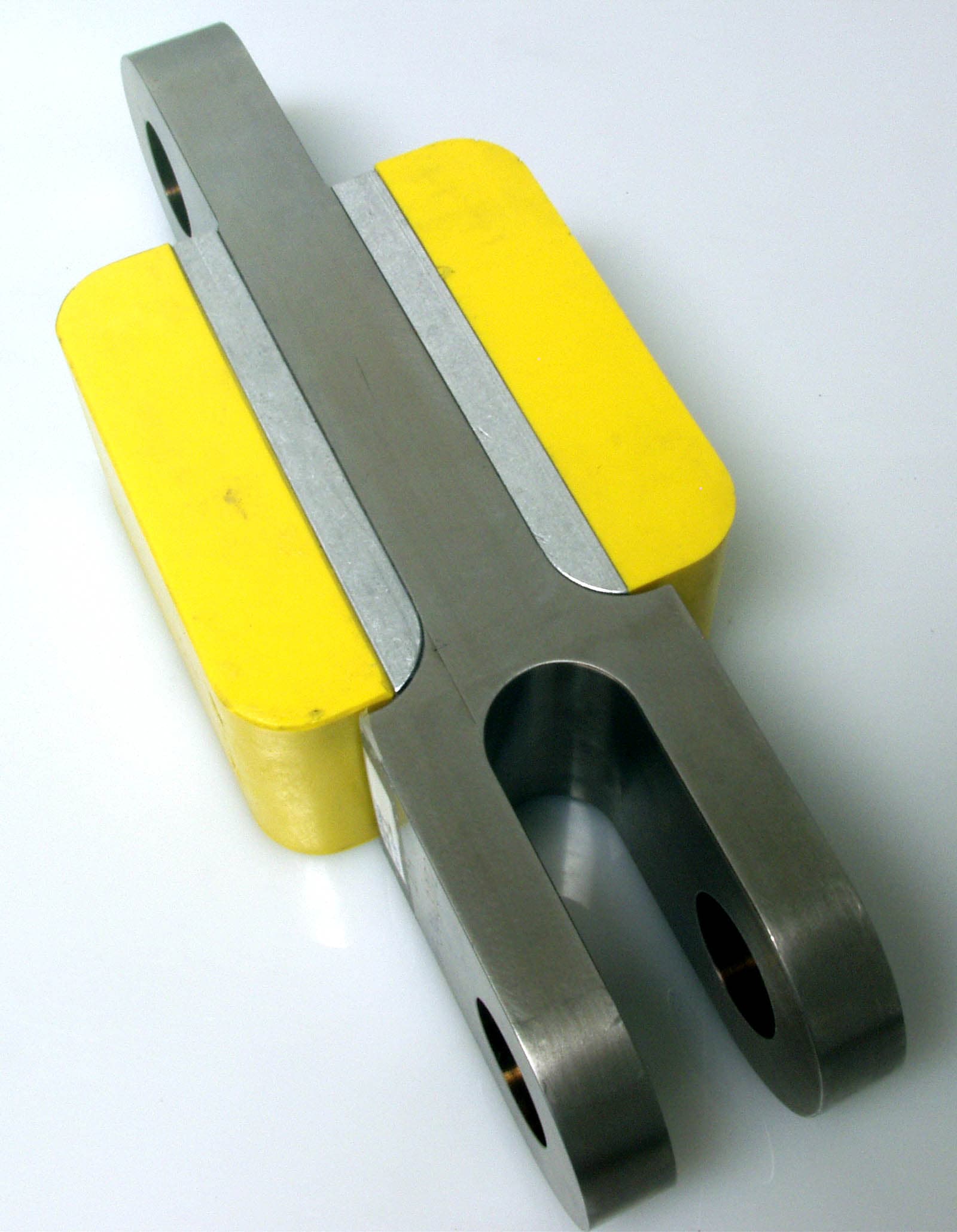
NFBLAB123
Aug 27, 2006Wireless Weight Transducer
Equipment Class
DXX - Part 15 Low Power Communication Device TransmitterNFBLAB939
Oct 02, 1997Anti-2-Block System Receiver
Equipment Class
CRR - Superregenerative ReceiverNFBLAB939SW
Oct 02, 1997Anti-2-Block System Transmitter
Equipment Class
DXX - Part 15 Low Power Communication Device TransmitterNFBLAB737
Sep 08, 1997Load Monitoring System Receiver
Equipment Class
CYY - Communications Receiver used w/Pt 15 Transmitter