NGTSNACATRBBA Wireless Electronic Shelf-label System
ERS International Inc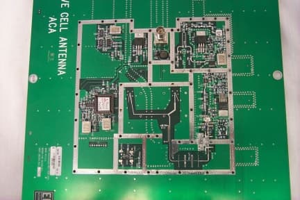
Click to zoom
Application Details
- Equipment Class
- DSS - Part 15 Spread Spectrum Transmitter
- Date of Grant
- Sep 27, 1999
- Application Purpose
- Original Equipment
- Date of Application
- Jun 29, 1999
- Equipment Note
- A Wireless Electronic Shelf-label System
- Frequency Range
- 2409.80000000 - 2469.80000000
- Company
- ERS International Inc
- Country
- United States
Documents & Files
Document Text
Text extracted from the exhibit documents filed with the FCC. Open a document above to read the original.
Users Manual
Warranty Return Card for ERSActive Cell Antenna (ACA)sDear Customer:This ACA is warranted to be free from defects inmaterials and workmanship during its usefullifetime. In the event it proves to be defective,please complete this form and return it, along withthe defective ACA, to Electronic RetailingSystems International, Inc..ERS values your comments, and will use theinformation you provide to continuously improveour products and services. Thank you for yourcooperation.Model Number: _________________________ Serial Number: _________________________ Date of Installation: ______________________ Name :_______________________________ Address :_____________________________ City, State, Zip: _________________________ Area Code/Phone Number :________________ Description of Problem :__________________ ________________________________________________________________________________________________________________________________________________ ACTIVE CELL ANTENNAThe ACAs physical dimensions are; 24.5 in. (L) X 13.02in. (W) X 3.31 in. (H) 62.23 cm.(L) X 33.07 cm. (W) X 8.41 cm (H) These devices have 2 LED indicators at their outside edge, one red and one green. When lit,the green LED indicator signifies that d-cpower is applied. A single BNC connector is located at the top center of the assembly. Depending oncustomer requirements, some ACAs aredelivered with dust- and moisture-resistantcovers. At least 5 inches should be allowed forclearance of the ACA i-f cable. The ACA requires 15-volt d-c power, which is supplied through the RG-58 i-f cable shield andcenter conductor. Suitable filtering in the ACAisolates d-c from the radio-frequency signaland the r-f signal from the d-c power bus. Electronic Retailing Systems International, Inc.488 Main AvenueNorwalk, CT. 06851-1007 Part Number 957005-BA Active Cell Antenna SN-ACATR-00 Installation Instruction Guide Mounting an ACA:The optimum mounting height for an ACA is from12 to 15 feet above the floor. ACAs must alwaysbe installed with an unobstructed free area of atleast two (2) feet beneath it. In all cases, the ACA should be at a minimum height of eight(8) feet so long as a minimum of (8) inchesseparation is maintained between the ACAand any human contact during operation.There are two primary methods of mounting anACA in order to remain within that height range.One is for the suspended ceiling that isconstructed of a steel frame with tile inserts andis within the height range. The other is designedfor an open ceiling or a suspended ceiling that ishigher than 15 feet.The package your ACA was delivered in has aplastic packet that contains two (2) T-bar clipsand two (2) S-hooks. The T-bar clips will snaponto the T-bars of the suspended ceiling (asshown in Figure 1), providing a loop for the S-hook which will attach to the ACA hanging straps. ACA mounting During installation, check that both ends of allcoaxial cables are marked.Taking aisle direction into account (Figure 1),mark the ceiling-tile frame opposite the placewhere the coaxial cable feeds through the ceilingtile. Measure 5-inches in both direction on theceiling frame and snap a T-bar clip in place (5)onthe ceiling tile T-bar frame at each measuredspot.Feed one end of an S hook (Figure 1) throughone of the T-bar clip eyes and the other end ofthe same S hook through the ACA bracket eye.Do the same with the second T-bar clip and theother ACA bracket eye. MCC to ACA cable connections should be madeas each ACA is installed.Make sure that the cable from the MCC does notbind on the hole through the ceiling tiles (item 3 ofFigure 1), also make sure that the stress relief onthe cable to the MCC does not exert any pressureon the ACA which might disrupt its level position.You should check the level of the ACA after it ismounted to insure that it is level both parallel withand perpendicular to the aisle.The antenna being out of level will dramaticallyaffect the RF energy transmission and therebythe efficiency of the entire system. 23 5 5 - IN, 5 1 CEILING TILE FRAME 2 AISLE DIRECTION3 COAXIAL CABLE FEEDTHROUGH 4 ACA5 T-BAR CLIP 1 SS _ TR302.DOC 4
Users Manual
Warranty Return Card for ERSActive Cell Antenna (ACA)sDear Customer:This ACA is warranted to be free from defects inmaterials and workmanship during its usefullifetime. In the event it proves to be defective,please complete this form and return it, along withthe defective ACA, to Electronic RetailingSystems International, Inc..ERS values your comments, and will use theinformation you provide to continuously improveour products and services. Thank you for yourcooperation.Model Number: _________________________ Serial Number: _________________________ Date of Installation: ______________________ Name :_______________________________ Address :_____________________________ City, State, Zip: _________________________ Area Code/Phone Number :________________ Description of Problem :__________________ ________________________________________________________________________________________________________________________________________________ ACTIVE CELL ANTENNAThe ACAs physical dimensions are; 24.5 in. (L) X 13.02in. (W) X 3.31 in. (H) 62.23 cm.(L) X 33.07 cm. (W) X 8.41 cm (H) These devices have 2 LED indicators at their outside edge, one red and one green. When lit,the green LED indicator signifies that d-cpower is applied. A single BNC connector is located at the top center of the assembly. Depending oncustomer requirements, some ACAs aredelivered with dust- and moisture-resistantcovers. At least 5 inches should be allowed forclearance of the ACA i-f cable. The ACA requires 15-volt d-c power, which is supplied through the RG-58 i-f cable shield andcenter conductor. Suitable filtering in the ACAisolates d-c from the radio-frequency signaland the r-f signal from the d-c power bus. Electronic Retailing Systems International, Inc.488 Main AvenueNorwalk, CT. 06851-1007 Part Number 957005-BA Active Cell Antenna SN-ACATR-00 Installation Instruction Guide Mounting an ACA:The optimum mounting height for an ACA is from12 to 15 feet above the floor. ACAs must alwaysbe installed with an unobstructed free area of atleast two (2) feet beneath it. In all cases, the ACA should be at a minimum height of eight(8) feet so long as a minimum of (8) inchesseparation is maintained between the ACAand any human contact during operation.There are two primary methods of mounting anACA in order to remain within that height range.One is for the suspended ceiling that isconstructed of a steel frame with tile inserts andis within the height range. The other is designedfor an open ceiling or a suspended ceiling that ishigher than 15 feet.The package your ACA was delivered in has aplastic packet that contains two (2) T-bar clipsand two (2) S-hooks. The T-bar clips will snaponto the T-bars of the suspended ceiling (asshown in Figure 1), providing a loop for the S-hook which will attach to the ACA hanging straps. ACA mounting During installation, check that both ends of allcoaxial cables are marked.Taking aisle direction into account (Figure 1),mark the ceiling-tile frame opposite the placewhere the coaxial cable feeds through the ceilingtile. Measure 5-inches in both direction on theceiling frame and snap a T-bar clip in place (5)onthe ceiling tile T-bar frame at each measuredspot.Feed one end of an S hook (Figure 1) throughone of the T-bar clip eyes and the other end ofthe same S hook through the ACA bracket eye.Do the same with the second T-bar clip and theother ACA bracket eye. MCC to ACA cable connections should be madeas each ACA is installed.Make sure that the cable from the MCC does notbind on the hole through the ceiling tiles (item 3 ofFigure 1), also make sure that the stress relief onthe cable to the MCC does not exert any pressureon the ACA which might disrupt its level position.You should check the level of the ACA after it ismounted to insure that it is level both parallel withand perpendicular to the aisle.The antenna being out of level will dramaticallyaffect the RF energy transmission and therebythe efficiency of the entire system. 23 5 5 - IN, 5 1 CEILING TILE FRAME 2 AISLE DIRECTION3 COAXIAL CABLE FEEDTHROUGH 4 ACA5 T-BAR CLIP 1 SS _ TR302.DOC 4
ID Label/Location Info
ERS International, Inc. 488 Main Ave.Norwalk, CT. 06851-1007 FCC ID: NGTSNACATRBB This Device complies with Part 15 of the FCCRules. Operation is subject to one of the twofollowing conditions.(1) This device may not cause harmful interference and (2) This device must accept any interference received, including interference that maycause undesired operations. ERS Model No. : SN-ACATR-11 Part Number : 392702 Rev. : Unit Address : 0X3FF0 Lot Number : ShelfNet ERS 065008 MADE IN USA ERS International, Inc. 488 Main Ave.Norwalk, CT. 06851-1007 FCC ID: NGTSNACATRBB This Device complies with Part 15 of the FCCRules. Operation is subject to one of the twofollowing conditions.(1) This device may not cause harmful interference and (2) This device must accept any interference received, including interference that maycause undesired operations. ERS Model No. : SN-ACATR-11 Part Number : 392702 Rev. : Unit Address : 0X3FF0 Lot Number : ShelfNet ERS 065008 MADE IN USA ERS International, Inc. 488 Main Ave.Norwalk, CT. 06851-1007 FCC ID: NGTSNACATRBB This Device complies with Part 15 of the FCCRules. Operation is subject to one of the twofollowing conditions.(1) This device may not cause harmful interference and (2) This device must accept any interference received, including interference that maycause undesired operations. ERS Model No. : SN-ACATR-11 Part Number : 392702 Rev. : Unit Address : 0X3FF0 Lot Number : ShelfNet ERS 065008 MADE IN USA ERS International, Inc. 488 Main Ave.Norwalk, CT. 06851-1007 FCC ID: NGTSNACATRBB This Device complies with Part 15 of the FCCRules. Operation is subject to one of the twofollowing conditions.(1) This device may not cause harmful interference and (2) This device must accept any interference received, including interference that maycause undesired operations. ERS Model No. : SN-ACATR-11 Part Number : 392702 Rev. : Unit Address : 0X3FF0 Lot Number : ShelfNet ERS 065008 MADE IN USA ERS International, Inc. 488 Main Ave.Norwalk, CT. 06851-1007 FCC ID: NGTSNACATRBB This Device complies with Part 15 of the FCCRules. Operation is subject to one of the twofollowing conditions.(1) This device may not cause harmful interference and (2) This device must accept any interference received, including interference that maycause undesired operations. ERS Model No. : SN-ACATR-11 Part Number : 392702 Rev. : Unit Address : 0X3FF0 Lot Number : ShelfNet ERS 065008 MADE IN USA ERS International, Inc. 488 Main Ave.Norwalk, CT. 06851-1007 FCC ID: NGTSNACATRBB This Device complies with Part 15 of the FCCRules. Operation is subject to one of the twofollowing conditions.(1) This device may not cause harmful interference and (2) This device must accept any interference received, including interference that maycause undesired operations. ERS Model No. : SN-ACATR-11 Part Number : 392702 Rev. : Unit Address : 0X3FF0 Lot Number : ShelfNet ERS 065008 MADE IN USA
Operational Description
Electronic Retailing Systems International, Inc. 488 Main Avenue Norwalk, CT 06851-1007 Part Number 957002 ShelfNet System User’s Guide March 1999 User’s Guide ii Copyright 1999 by Electronic Retailing Systems International, Inc. (ERS). All rights reserved. This guide contains proprietary information protected by copyright. This guide is intended for use by customers of ERS and should be disclosed within the customer’s organization on a “need to know” basis. This guide shall not be reproduced by any means, stored on magnetic media, or made available directly or indirectly to any third party, without prior written consent of ERS. Program listings may be entered, stored, and executed in a computer system, but may not be reproduced for publication. The information in this guide is subject to change without notice and should not be construed as a commitment by ERS, which expressly disclaims any warranties, express or implied, including any implied warranty of merchantability or fitness for a particular purpose and assumes no liability for errors or omissions in this guide or any damages, direct or consequential resulting therefrom. EPMS (Electronic Price Management System) is a registered trademark and ShelfServer, ShelfNet, QuickP.O.P., AccuStock, PowerKey, RailGuard, and PromoFlash are trademarks of ERS. UNIX is a registered trademark in the United States and other countries, licensed through X/Open Company Limited. X/Open is a trademark of X/Open Company in the UK and in other countries. ELT and LabelMaster are registered trademarks of Electronic Label Technology, Broken Arrow, Oklahoma 74012-8913. Send Inquiries or comments to: ERS International, Inc. 488 Main Avenue Norwalk, CT 06851-1007 Voice: 203 - 849 - 2500 Fax: 203 - 849 - 2501 User’s Guide iii USA Electronic Emission Notice FCC Radio Frequency Interference Statement The ERS products discussed in this document control the ERS EasyLabels Shelfnet system. The ShelfNet equipment in this system has been tested and found to comply with the limits for a class A digital device, pursuant to Part 15 of the FCC rules. These limits are designed to provide reasonable protection again harmful interference when the equipment is operated in a commercial environment. This equipment uses and generates radio frequency energy. If this equipment is not installed and used in accordance with the instructions in this document, harmful interference to radio communications may result. User Information This equipment complies with Part 15 of the FCC rules. Operation is subject to the two following conditions: 1. This equipment does not cause harmful interference. 2. This equipment must accept any interference received, including interference that may cause undesired oper- ation. User Caution The Federal Communications Commission warns users that changes or modifications to this equipment not expressly approved by ERS may void the user’s authority to operate this equipment. User’s Guide iv Canadian Electronic Emission Notice This Class A digital apparatus meets all requirements of the Canadian Interference-Causing Equipment Regulations. Cet appareil numerique de la classe A respecte toutes les exigences du Reglement sur le materiel brouilleur du Canada. The Active Cell Antenna (ACA) discussed in this document complies with RSS-210 of Industry Canada. Operation is subject to the following two conditions: 1. This device may not cause harmful interference. 2. This device must accept any interference, including in- terference that may cause undesired operation of the device. User’s Guide CONTENTS Contents-v USA Electronic Emission Notice Canadian Electronic Emission Notice Welcome To The ShelfNet System Chapter 1. Overview of ERS Shelf Label System 1.1 System Description ..................................................................................... 1-1 1.1.1 ShelfNet System Topology ..................................................................... 1-1 1.1.2 In Store Processor (ISP) ........................................................................ 1-3 1.1.3 Point of Sale System (POS) ................................................................... 1-3 1.2 ShelfNet Components ................................................................................ 1-3 1.2.1 Multi-Cell Controller (MCC) .................................................................... 1-3 1.2.2 Active-Cell Antenna (ACA) ..................................................................... 1-3 1.2.3 Electronic Shelf Labels (ESLs) ............................................................... 1-4 1.2.3.1 ESL Buttons ........................................................................................ 1-5 1.2.3.2 Overlays .............................................................................................. 1-6 1.2.4 Handheld Terminal ................................................................................. 1-6 1.2.5 10-Base-T Hub ....................................................................................... 1-6 1.2.6 Host System ........................................................................................... 1-7 Chapter 2. ShelfServer Navigation 2.1 ShelfServer User Interface .......................................................................... 2-1 2.1.1 Logging-On and Logging-Off .................................................................. 2-1 2.1.2 Exiting ShelfServer ................................................................................. 2-3 2.2 ShelfServer Main Menu ............................................................................... 2-4 2.2.1 Screen Title ............................................................................................ 2-5 2.2.2 Status Indicators .................................................................................... 2-5 2.2.3 Menu Items ............................................................................................ 2-6 2.3 User Interfa…
Text truncated - open the document above for the full version.
Operational Description
Electronic Retailing Systems International, Inc. 488 Main Avenue Norwalk, CT 06851-1007 Part Number 957009 ShelfNet System Planning and Installation Guide June 1999 Planning and Installation Guide ii Copyright 1999 by Electronic Retailing Systems International, Inc. (ERS). All rights reserved. This guide contains proprietary information protected by copyright. This guide is intended for use by customers of ERS and should be disclosed within the customer’s organization on a “need to know” basis. This guide shall not be reproduced by any means, stored on magnetic media, or made available directly or indirectly to any third party, without prior written consent of ERS. Program listings may be entered, stored, and executed in a computer system, but may not be reproduced for publication. The information in this guide is subject to change without notice and should not be construed as a commitment by ERS, which expressly disclaims any warranties, express or implied, including any implied warranty of merchantability or fitness for a particular purpose and assumes no liability for errors or omissions in this guide or any damages, direct or consequential resulting therefrom. EPMS (Electronic Price Management System) is a registered trademark and ShelfServer, ShelfNet, QuickP.O.P., AccuStock, PowerKey, RailGuard, and PromoFlash are trademarks of ERS. UNIX is a registered trademark in the United States and other countries, licensed through X/Open Company Limited. X/Open is a trademark of X/Open Company in the UK and in other countries. ELT and LabelMaster are registered trademarks of Electronic Label Technology, Broken Arrow, Oklahoma 74012-8913. Send Inquiries or comments to: ERS International, Inc. 488 Main Avenue Norwalk, CT 06851-1007 Voice: 203 - 849 - 2500 Fax: 203 - 849 - 2501 Planning and Installation Guide iii USA Electronic Emission Notice FCC Radio Frequency Interference Statement The ERS products discussed in this document control the ERS EasyLabels Shelfnet system. The ShelfNet equipment in this system has been tested and found to comply with the limits for a class A digital device, pursuant to Part 15 of the FCC rules. These limits are designed to provide reasonable protection again harmful interference when the equipment is operated in a commercial environment. This equipment uses and generates radio frequency energy. If this equipment is not installed and used in accordance with the instructions in this document, harmful interference to radio communications may result. User Information This equipment complies with Part 15 of the FCC rules. Operation is subject to the two following conditions: 1. This equipment does not cause harmful interference. 2. This equipment must accept any interference received, including interference that may cause undesired oper- ation. User Caution The Federal Communications Commission warns users that changes or modifications to this equipment not expressly approved by ERS may void the user’s authority to operate this equipment. Planning and Installation Guide iv Canadian Electronic Emission Notice This Class A digital apparatus meets all requirements of the Canadian Interference-Causing Equipment Regulations. Cet appareil numerique de la classe A respecte toutes les exigences du Reglement sur le materiel brouilleur du Canada. The Active Cell Antenna (ACA) discussed in this document complies with RSS-210 of Industry Canada. Operation is subject to the following two conditions: 1. This device may not cause harmful interference 2. This device must accept any interference, including in- terference that may cause undesired operation of the device Planning and Installation Guide CONTENTS Contents - v USA Electronic Emission Notice Canadian Electronic Emission Notice Welcome To The ShelfNet System About this Publication .............................................................................. ix Organization .............................................................................................. ix Typographical Conventions ...................................................................... xi Keyboard Conventions ............................................................................. xi Chapter 1 Pre-Installation Planning 1.1 Preparation .................................................................................................. 1-1 1.1.1 Required Tasks ....................................................................................... 1-1 1.1.2 Required Materials .................................................................................. 1-2 1.2 Creating the Store Layout ........................................................................... 1-2 1.2.1 Initial Layout ............................................................................................ 1-3 1.2.2 Procedure ................................................................................................ 1-4 1.3 Performing the Site Survey ......................................................................... 1-4 1.3.1 Prerequisite Information .......................................................................... 1-5 1.3.2 Site Survey Checklist .............................................................................. 1-5 1.3.2.1 Host System Checklist ......................................................................... 1-5 1.3.2.2 Existing Peripherals Survey ................................................................. 1-7 1.3.2.3 MCC Placment Survey ......................................................................... 1-7 1.3.2.4 General Layout Information .................................................................. 1-7 1.3.3 Aisle Survey ............................................................................................ 1-8 1.3.3.1 Measurement Guidelines ..................................................................... 1-9 1.3.3.2 Aisle Survey Procedure .....................................................…
Text truncated - open the document above for the full version.
RF Exposure Info
Radiofrequency radiation exposure prediction from ShelfNet System For calculation the RF exposure we apply a worst possible case scenario where multiple systems are installed in a single location. In this scenario, there is the potential for more than one transmitter to be generating RF at the same point in time. We have determined that the worst case scenario is as follows: four transmitters located at the four corners of a square area of store space as illustrated below. The minimum spacing between any two transmitters is 9 m. The area of most potential RF field strength is directly in the middle of this square. This scenario places four transmitters around a central point with 6.0 m of distance from any transmitter to this central location. The worst case possible field strength is calculated by determining the field strength 6.0-m away from one transmitter, and then multiplying that number by four. 9m 6.0 m 9 m For ShelfNet transmitter peak power 0.94 W the field strength at 6 m can be calculated as: E = 30 P . G . d 2 = 30 0.94 . 4 . 6 2 = 3.13 v m If we converted V/m into power density mW/cm^2 we will receive: Power density = E 2 3770 = 3.13 2 3770 = 9.3 10 4 . mW cm 2 When 4 transmitters work simultaneously: Power dencity = 9.3 10 4 . 4 . = 0.0037 mW cm 2 The limit for Maximum Permissible Exposure (MPE) for General Population/Uncontrolled Exposure from Table 1 (1.1310 FCC Regulations) in frequency range 2.4 – 2.483 GHz defined as 1 mW/cm^2. It is clear, that 0.0037 mW/cm^2 make up only 0.37% of the 1 mW/cm^2, even without taking into account the averaging factor. Therefore, the RF exposure from ShelfNet System fully comply with FCC Radiofrequency Radiation Exposure Requirements (MPE). Aron Viner Manager Product Compliance ERS International Phone: 978 264 2885 Fax: 978 264 2801 E-mail: [email protected]
Test Report
Intertek Testing Services NA Inc. 70 Codman Hill Road Boxborough, MA 01719 Telephone (978) 263-2662 Fax (978) 263-7086 ERS International, Inc. Emissions Testing Performed on the Active Cell Antenna Model: SN-ACATR-11 FCC Part 15, Subpart C, '15.247 Date of Test: June 15, 1999 WO#J98015767A KPS/Rbt ERS5767A.KPS June 25, 1999 DOT: June 15, 1999 Contact: Mr. Aron Viner Total No. of Pages Contained in this Report: All services undertaken are subject to the following general policy: Reports are submitted for exclusive use of the client to whom they are addressed. Their significance is subject to the adequacy and representative character of the samples and to the comprehensiveness of the tests, examinations or surveys made. No quotations from reports or use of Intertek Testing Services name is permitted except as expressly authorized by Intertek Testing Services in writing. This report must not be used to claim product endorsement by NVLAP, NIST or any agency of the U.S. government. INTERTEK TESTING SERVICES NA INC. TO:Electronic Retail Systems Mr. Aron Viner FROM:Kouma P. Sinn DATE:June 15, 1999 RE:Emissions testing of the ShelfNet Active Cell Antenna, Model SN-ACATR-11 On June 15, 1999, we tested the ShelfNet Active Cell Antenna, Model: SN-ACATR- 11 to determine if it was compliant with the FCC Part 15 Subpart C Section '15.247 emission requirements. We found that the unit met the requirements when tested as received. Worst-case emissions results are as follows: FCC Part 15 Subpart C Section ''15.247 Table # TestFrequency (MHZ) Margin (dB) Next Highest Margin (dB) DetectorPass/Fail Transmitting at 2410 MHZ 1Radiated4819.6-22-66PeakPass Transmitting at 2440 MHZ 2Radiated7319.4-12-23PeakPass Transmitting at 2470 MHZ 3Radiated7409.4-9-23PeakPass FCC Part 15 Subpart C Section ''15.207 4 Line-Conducted 20.00-18.2-21.2Quasi-PeakPass Notes: An average factor of 3 dB was determined and applied to the readings prior comparing to the limit. See Derivation of Averaging Factor on Page 9. INTERTEK TESTING SERVICES NA INC. TO:Electronic Retail Systems Mr. Aron Viner FROM:Kouma P. Sinn DATE:June 15, 1999 RE:Emissions testing of the ShelfNet Active Cell Antenna, Model SN-ACATR-11 Measurements Of Output Power Frequency (MHZ) Distance (Meters) Net Reading (dBuv) Calculated Power (Watts) Limit (Watts) Pass/Fail 2409.8031300.7501.0Pass 2439.8031310.9401.0Pass 2469.8031300.7501.0Pass Output power was measured by recording the field strength for low, mid and high transmit frequencies. Peak measurements were taken at 3 meters test distance. Due to a lack of an RF port for the antenna, the field strength measurements were converted to a power level at the antenna terminal using the following formula: P = (E * d) 2 / (30 * G) Where: P = Power in Watts E = Measured Field Strength in Volts/meter d = Measuring distance in meters G = Numeric gain of the transmit antenna For the worst-case field strength the power was calculated as follows: P = ((10 (131/20) / 1E6) * 3) 2 / (30 * 4.0) = 0.940 Watts Notes: The gain of the transmit antenna is 6.0 dBi, which is numerically expressed as 4.0. The output power is expressed as peak measurements, without an averaging factor applied. The resolution bandwidth of the measuring receiver is 1 MHZ during power measurements. The video bandwidth of the measurement receiver is 300 KHZ during the power measurements. LABORATORY MEASUREMENTS INTERTEK TESTING SERVICES NA INC. Laboratory Measurements, Intentional RadiatorsJob Number: J99015767B Rev. September 1, 1992 (PT15C.IR) Introduction The following is a description of the test procedure used by Intertek Testing Services in the measurements of transmitters operating under Part 15, Subpart C, General Requirements. A.Test Set-Up: The test set-up and procedures described below are designed to meet the requirements of ANSI C63.4 (1992). 1.Site 2C (Middle Site) is a 3m and 10m sheltered EMI measurement range located in a light commercial environment in Boxborough, Massachusetts. It meets the technical requirements of ANSI C63.4-1992 and CISPR 22:1997/EN 55022:1994 for radiated and conducted emission measurements. The shelter structure is entirely fiberglass and plastic, with outside dimensions of 33 ft x 57 ft. The structure resembles a quonset hut with a center ceiling height of 16.5 ft. The testing floor is covered by a galvanized sheet metal groundplane that is earth-grounded via copper rods around the perimeter of the site. The joints between individual metal sheets are bridged with a 2 inch wide metal strips to provide low RF impedance contact throughout. The sheets of metal are screwed in place with stainless steel, round-head screws every three inches. Site illumination and HVAC are provided from beneath the ground reference plane through flush entry ports, the port covers are electrically bonded to the ground plane. A flush metal turntable with 12 ft. diameter and 5000 lb. load capacity is provided for floor- standing equipment. INTERTEK TESTING SERVICES NA…
Text truncated - open the document above for the full version.
Contact Information
Applicant
Frank Romano(Vice President, Engineering)
Technical Contact
Intertek Testing Services NA Inc.Andrew J Bellezza
[email protected]978-635-8641
70 Codman Hill Road · Boxborough, Massachusetts · United States
Non-Technical Contact
Intertek Testing Services NA Inc.Jody K Zarnowiec
[email protected]978-635-8693
Test Firm
Intertek Testing Services NA Inc.Diana Montvitt
508-263-2662
Technical Specifications
| # | Rule Parts | Frequency Range | Power Output |
|---|---|---|---|
| 1 | 15C | 2.41 GHz - 2.47 GHz | 940.00 mW |
Other Applications from ERS International Inc
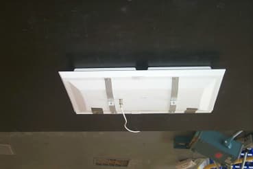
NGTSNACATRCC
Apr 19, 2001Active Cell Antenna
Equipment Class
DSS - Part 15 Spread Spectrum TransmitterNGTSNACATRAA
Jul 31, 1997Electronic Shelf-Label System Transmitter Maximum output power: 189 mW
Equipment Class
DSS - Part 15 Spread Spectrum Transmitter