NGTSNACATRCCActive Cell Antenna
ERS International Inc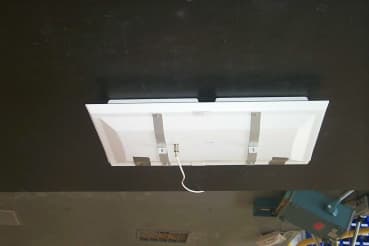
Click to zoom
Application Details
- Equipment Class
- DSS - Part 15 Spread Spectrum Transmitter
- Date of Grant
- Apr 19, 2001
- Application Purpose
- Original Equipment
- Date of Application
- Aug 24, 2000
- Equipment Note
- Active Cell Antenna
- Frequency Range
- 2403.00000000 - 2477.00000000
- Company
- ERS International Inc
- Country
- United States
Documents & Files
Document Text
Text extracted from the exhibit documents filed with the FCC. Open a document above to read the original.
Users Manual
Electronic Retailing Systems International, Inc. 488 Main Avenue Norwalk, CT 06851-1007 Part Number 957002 ShelfNet System User’s Guide March 1999 User’s Guide ii Copyright 1999 by Electronic Retailing Systems International, Inc. (ERS). All rights reserved. This guide contains proprietary information protected by copyright. This guide is intended for use by customers of ERS and should be disclosed within the customer’s organization on a “need to know” basis. This guide shall not be reproduced by any means, stored on magnetic media, or made available directly or indirectly to any third party, without prior written consent of ERS. Program listings may be entered, stored, and executed in a computer system, but may not be reproduced for publication. The information in this guide is subject to change without notice and should not be construed as a commitment by ERS, which expressly disclaims any warranties, express or implied, including any implied warranty of merchantability or fitness for a particular purpose and assumes no liability for errors or omissions in this guide or any damages, direct or consequential resulting therefrom. EPMS (Electronic Price Management System) is a registered trademark and ShelfServer, ShelfNet, QuickP.O.P., AccuStock, PowerKey, RailGuard, and PromoFlash are trademarks of ERS. UNIX is a registered trademark in the United States and other countries, licensed through X/Open Company Limited. X/Open is a trademark of X/Open Company in the UK and in other countries. ELT and LabelMaster are registered trademarks of Electronic Label Technology, Broken Arrow, Oklahoma 74012-8913. Send Inquiries or comments to: ERS International, Inc. 488 Main Avenue Norwalk, CT 06851-1007 Voice: 203 - 849 - 2500 Fax: 203 - 849 - 2501 User’s Guide iii USA Electronic Emission Notice FCC Radio Frequency Interference Statement The ERS products discussed in this document control the ERS EasyLabels Shelfnet system. The ShelfNet equipment in this system has been tested and found to comply with the limits for a class A digital device, pursuant to Part 15 of the FCC rules. These limits are designed to provide reasonable protection again harmful interference when the equipment is operated in a commercial environment. This equipment uses and generates radio frequency energy. If this equipment is not installed and used in accordance with the instructions in this document, harmful interference to radio communications may result. User Information This equipment complies with Part 15 of the FCC rules. Operation is subject to the two following conditions: 1. This equipment does not cause harmful interference. 2. This equipment must accept any interference received, including interference that may cause undesired oper- ation. User Caution The Federal Communications Commission warns users that changes or modifications to this equipment not expressly approved by ERS may void the user’s authority to operate this equipment. User’s Guide iv Canadian Electronic Emission Notice This Class A digital apparatus meets all requirements of the Canadian Interference-Causing Equipment Regulations. Cet appareil numerique de la classe A respecte toutes les exigences du Reglement sur le materiel brouilleur du Canada. The Active Cell Antenna (ACA) discussed in this document complies with RSS-210 of Industry Canada. Operation is subject to the following two conditions: 1. This device may not cause harmful interference. 2. This device must accept any interference, including in- terference that may cause undesired operation of the device. User’s Guide CONTENTS Contents-v USA Electronic Emission Notice Canadian Electronic Emission Notice Welcome To The ShelfNet System Chapter 1. Overview of ERS Shelf Label System 1.1 System Description ..................................................................................... 1-1 1.1.1 ShelfNet System Topology ..................................................................... 1-1 1.1.2 In Store Processor (ISP) ........................................................................ 1-3 1.1.3 Point of Sale System (POS) ................................................................... 1-3 1.2 ShelfNet Components ................................................................................ 1-3 1.2.1 Multi-Cell Controller (MCC) .................................................................... 1-3 1.2.2 Active-Cell Antenna (ACA) ..................................................................... 1-3 1.2.3 Electronic Shelf Labels (ESLs) ............................................................... 1-4 1.2.3.1 ESL Buttons ........................................................................................ 1-5 1.2.3.2 Overlays .............................................................................................. 1-6 1.2.4 Handheld Terminal ................................................................................. 1-6 1.2.5 10-Base-T Hub ....................................................................................... 1-6 1.2.6 Host System ........................................................................................... 1-7 Chapter 2. ShelfServer Navigation 2.1 ShelfServer User Interface .......................................................................... 2-1 2.1.1 Logging-On and Logging-Off .................................................................. 2-1 2.1.2 Exiting ShelfServer ................................................................................. 2-3 2.2 ShelfServer Main Menu ............................................................................... 2-4 2.2.1 Screen Title ............................................................................................ 2-5 2.2.2 Status Indicators .................................................................................... 2-5 2.2.3 Menu Items ............................................................................................ 2-6 2.3 User Interfa…
Text truncated - open the document above for the full version.
External Photos
Exterior photos
ID Label/Location Info
ERS International, Inc. 488 Main Ave.Norwalk, CT. 06851-1007 FCC ID: NGTSNACATRBB This Device complies with Part 15 of the FCCRules. Operation is subject to one of the twofollowing conditions.(1) This device may not cause harmful interference and (2) This device must accept any interference received, including interference that maycause undesired operations. ERS Model No. : SN-ACATR-11 Part Number : 392702 Rev. : Unit Address : 0X3FF0 Lot Number : ShelfNet ERS 065008 MADE IN USA ERS International, Inc. 488 Main Ave.Norwalk, CT. 06851-1007 FCC ID: NGTSNACATRBB This Device complies with Part 15 of the FCCRules. Operation is subject to one of the twofollowing conditions.(1) This device may not cause harmful interference and (2) This device must accept any interference received, including interference that maycause undesired operations. ERS Model No. : SN-ACATR-11 Part Number : 392702 Rev. : Unit Address : 0X3FF0 Lot Number : ShelfNet ERS 065008 MADE IN USA ERS International, Inc. 488 Main Ave.Norwalk, CT. 06851-1007 FCC ID: NGTSNACATRBB This Device complies with Part 15 of the FCCRules. Operation is subject to one of the twofollowing conditions.(1) This device may not cause harmful interference and (2) This device must accept any interference received, including interference that maycause undesired operations. ERS Model No. : SN-ACATR-11 Part Number : 392702 Rev. : Unit Address : 0X3FF0 Lot Number : ShelfNet ERS 065008 MADE IN USA ERS International, Inc. 488 Main Ave.Norwalk, CT. 06851-1007 FCC ID: NGTSNACATRBB This Device complies with Part 15 of the FCCRules. Operation is subject to one of the twofollowing conditions.(1) This device may not cause harmful interference and (2) This device must accept any interference received, including interference that maycause undesired operations. ERS Model No. : SN-ACATR-11 Part Number : 392702 Rev. : Unit Address : 0X3FF0 Lot Number : ShelfNet ERS 065008 MADE IN USA ERS International, Inc. 488 Main Ave.Norwalk, CT. 06851-1007 FCC ID: NGTSNACATRBB This Device complies with Part 15 of the FCCRules. Operation is subject to one of the twofollowing conditions.(1) This device may not cause harmful interference and (2) This device must accept any interference received, including interference that maycause undesired operations. ERS Model No. : SN-ACATR-11 Part Number : 392702 Rev. : Unit Address : 0X3FF0 Lot Number : ShelfNet ERS 065008 MADE IN USA ERS International, Inc. 488 Main Ave.Norwalk, CT. 06851-1007 FCC ID: NGTSNACATRBB This Device complies with Part 15 of the FCCRules. Operation is subject to one of the twofollowing conditions.(1) This device may not cause harmful interference and (2) This device must accept any interference received, including interference that maycause undesired operations. ERS Model No. : SN-ACATR-11 Part Number : 392702 Rev. : Unit Address : 0X3FF0 Lot Number : ShelfNet ERS 065008 MADE IN USA
ID Label/Location Info
ERS International, Inc. 488 Main Ave. Norwalk, CT. 06851-1007 FCC ID: NGTSNACATRCC This Device complies with Part 15 of the FCC Rules. Operation is subject to one of the two following conditions. (1) This device may not cause harmful interference and (2) This device must accept any interference received, including interference that may cause undesired operations. ERS Model No. : SN- ACATR-11 Part Numbe r : 392702 Rev. : Serial Numbe r :0X3FF0 Lot Number : ShelfNet ERS 065004 MADE IN USA
Internal Photos
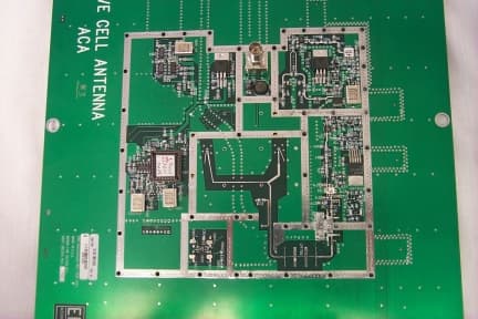
Certification Photographs Photograph 1: Model SN-ACATR-11 with top cover removed. Certification Photographs Photograph 2: Model SN-ACATR-11 removed from bottom cover. Certification Photographs Photograph 3: Model SN-ACATR-11 with no covers, picture is of upper portion of device. Certification Photographs Photograph 4: Model SN-ACATR-11 with covers removed, picture is of the bottom of the device
RF Exposure Info
Here are calculations which show compliance of the ERS active cell antenna with FCC section 15.247(b)(4): According to Table 1 in 1.1310, Radiofrequency Radiation Exposure Limits, the maximum permissible exposure (MPE) for general population/uncontrolled exposure at frequencies above 1500 MHz (the antenna operates between 2.403 and 2.477 GHz) is a power density of 1mW/cm 2 . This calculation computes the minimum distance away from the active cell antenna that an individual can be while staying within the safe exposure limits as defined by the aforementioned table. According to the ERS Shelfnet Technical Description, the peak antenna gain of the active cell antenna is 6dB, and the amplifier used has a typical amplification of 29dB, so the Effective Radiated Power (ERP) is 35dBm. The power density, P, at any point a radial distance r from the antenna is given by: P=ERP / (4*Pi *r 2 ) With P=1mW/cm 2 ERP=35dBm Converting ERP to milliWatts: ERP=35dBm=10Log(ERP mW ) ERP mW =3160 mW Solving for r, we obtain: r=(3200/(4*Pi)) 1/2 Which results in r=16cm So the minimum acceptable distance the active cell antenna can be located away from any given individual is 16 centimeters. Since the antenna is a ceiling mounted device, it will never be within this minimum distance. Therefore the antenna complies with 15.247(b)(4).
Test Report
Emissions Testing Performed on the: ERS International, Inc. Model: SN-ACATR-11 To FCC Part 15 Subpart C Intentional Radiators Date of Test: June 20, 21 and 29, 2000 JOB #: J20015003 DOT: June 20, 21 & 29, 2000 Contact: Steve Flynn Total No. of Pages Contained in this Report: 24 All services undertaken are subject to the following general policy: Reports are submitted for exclusive use of the client to whom they are addressed. Their significance is subject to the adequacy and representative character of the samples and to the comprehensiveness of the tests, examinations or surveys made. No quotations from reports or use of Intertek Testing Services NA Inc. name is permitted except as expressly authorized by Intertek Testing Services NA Inc. in writing. This report must not be used to claim product endorsement by NVLAP, NIST or any other agency of the U.S. Government. A Intertek Testing Services NA Inc. 70 Codman Hill Road Boxborough, Massachusetts 01719 Telephone: (978) 263-2662 Fax: (978) 263-7086 INTERTEK TESTING SERVICES NA INC. Laboratory Measurements, Intentional RadiatorsJob Number: J20015003 Page 2 of 24 This document may not be reproduced except in its entirety without written permission of ITS. TO:Steve Flynn FROM:Andy Bellezza DATE:July 14, 2000 JOB #:J20015003 RE:Emissions Testing Performed On The Active Cell Antenna, Model: SN-ACATR-11 On June 20, 21 and 29, 2000 we tested the Active Cell Antenna, Model: SN-ACATR- 11 to determine if it was in compliance with the FCC Part 15, Subpart C, and Sections §15.207, §15.209 and §15.247. A production version of the sample was received on June 20, 2000 in good condition. We found that the unit met the Part 15 requirements when tested as received. Fundamental Field Strength and Harmonic Scan: Fundamental output power is regulated under §15.247. Harmonic emissions, which lie in the forbidden bands of §15.205, are required to meet the General Radiated Emission Limits of §15.209. The maximum level of the fundamental signal at 2469.00 MHz was 109.1 dBμV/m, which is 23.9 dB below the FCC limit (see table 3). The worst case harmonic emission was 8.1 dB below the FCC Part 15 Subpart C limit. Average Factor: Please note that an average factor was applied to the level of the fundamental emission for comparison to the FCC limits. A duty cycle of 58% was measured, and the corresponding average factor of – 4.8 dB was determined and applied to the measured results. INTERTEK TESTING SERVICES NA INC. Laboratory Measurements, Intentional RadiatorsJob Number: J20015003 Page 3 of 24 This document may not be reproduced except in its entirety without written permission of ITS. Occupied Bandwidth Measurement: The maximum occupied bandwidth is determined in §15.247 (ii). For frequency hopping systems the maximum 20-dB bandwidth is equal to 1.0 MHz. The measured bandwidth of this signal was 143 KHz, which is significantly less than the FCC requirement. A bandwidth plot is shown in plot 1 at the end of this report. Summary: In summary, this report confirms that the Active Cell Antenna, Model: SN-ACATR- 11 is compliant with the FCC Part 15, Subpart C requirements when production units conform with the initial sample. Please address all questions and comments concerning this report to, Candy Campbell, ITE Team Leader . INTERTEK TESTING SERVICES Laboratory Measurements, Intentional RadiatorsJob Number: J20015003 Page 4 of 24 This document may not be reproduced except in its entirety without written permission of ITS. LABORATORY MEASUREMENTS Pursuant To Part 15 Subpart C For Intentional Radiators Manufacturer (Name and Address):ERS International, Inc. 488 Main Avenue Norwalk, CT 06851 Attention:Mr. Steve Flynn Model Number:SN-ACATR-11 Serial Number:#4 Certification We attest to the accuracy of this report: SignatureSignature Andrew BellezzaCandy L. Campbell Testing Performed ByReviewer Senior Project EngineerITE Engineering Team Leader TitleTitle INTERTEK TESTING SERVICES Laboratory Measurements, Intentional RadiatorsJob Number: J20015003 Page 5 of 24 This document may not be reproduced except in its entirety without written permission of ITS. Introduction The following is a description of the test procedure used by Intertek Testing Services in the measurements of transmitters operating under §15.209, General Requirements. A.Test Set-Up: The test set-up and procedures described below are designed to meet the requirements of ANSI C63.4 (1992). 1.The test site is a fiberglass structure with a ground-plane. The site has attenuation characteristics, which meet the requirements of ANSI C63.4 (1992). Information on the site has been filed with the FCC as required by Rule §2.948. The address of the site is 70 Codman Hill Road, Boxborough, MA 01719. 2.Power to the site is nominal line voltage of 117 V AC and 230 V AC , 60 Hz. 3.The equipment under test (EUT) is placed on a wooden turntable, which is 1.0 meter by 1.5 meters in diameter and 0.8 meters in height above the ground-plane. During the radiated emissions test, the turntable is rotated and any cables leaving the EUT are manipulated to find the configuration resulting in maximum emissions. The antenna height and polarization are also varied during the search for maximum signal levels. The height of the antenna is varied from one meter to four meters. 4.Detector function for radiated emissions is in peak or quasi-peak mode. Average readings, when required, are taken by measuring the duty cycle of the equipment under test and subtracting the corresponding amount in dB from the measured peak readings according to the following formula: Averaging Factor in dB = 20 LOG (duty cycle) INTERTEK TESTING SERVICES Laboratory Measurements, Intentional RadiatorsJob Number: J20015003 Page 6 of 24 This document may not be reproduced except in its entirety without written permission of ITS. A.Test Set Up (cont'd) The time period over which the duty cycle is measured is 100 msec. The worst-case (highest percentage on) duty cycle is use…
Text truncated - open the document above for the full version.
Contact Information
Applicant
Frank Romano(Vice President, Engineering)
Technical Contact
Intertek Testing Services, NA Inc.Andrew J Bellezza
[email protected](978) 263-2662
70 Codman Hill Road · Boxborough, Massachusetts · United States
Test Firm
Intertek Testing Services, NA Inc.Robert Martin
Technical Specifications
| # | Rule Parts | Frequency Range | Power Output |
|---|---|---|---|
| 1 | 15C | 2.40 GHz - 2.48 GHz | 794.00 mW |
Other Applications from ERS International Inc
NGTSNACATRBB
Sep 27, 1999A Wireless Electronic Shelf-label System
Equipment Class
DSS - Part 15 Spread Spectrum TransmitterNGTSNACATRAA
Jul 31, 1997Electronic Shelf-Label System Transmitter Maximum output power: 189 mW
Equipment Class
DSS - Part 15 Spread Spectrum Transmitter