NH5-FWTX1WUltralink Video Transmitter
Backgrounds Unlimited Inc
Click to zoom
Application Details
- Equipment Class
- TNB - Licensed Non-Broadcast Station Transmitter
- Date of Grant
- Jun 22, 2003
- Application Purpose
- Original Equipment
- Date of Application
- Jun 22, 2003
- Equipment Note
- Ultralink Video Transmitter
- Frequency Range
- 2463.00000000 - 2463.00000000
- Company
- Backgrounds Unlimited Inc
- Country
- United States
Documents & Files
Document Text
Text extracted from the exhibit documents filed with the FCC. Open a document above to read the original.
Users Manual
Rhein Tech Laboratories Client: Backgrounds Unlimited, Inc. 360 Herndon Parkway Model: TXBD1W Suite 1400 FCC ID: NH5-FWTX1W Herndon, VA 20170 Standards: FCC Part 90/IC RSS-210 http://www.rheintech.com Report Number: 2003073 34 of 46 APPENDIX I: MANUAL USER’S MANUAL Ultralink Video Transmitter Model Number: TXBD1W FCC ID NUMBER: NH5-FWTX1W Backgrounds Unlimited, Inc. P.O. Box 327 Mt. Sidney, VA 24467 (540) 248-0355 (540) 248-0920 fax [email protected] Description and Applications of the System The Ultralink Video Transmitter II (Model TXBD1W) is a long range video Transmitter intended for Government or Law Enforcement use. The unit can be set up within a matter of minutes and will transmit clear black and white or color video to the receiver. The TXBD1W accepts input from an NTSC video source, typically a camera. The TXBD1W is supplied with the following: (1) Ultralink Video Transmitter II (1) Receiver (1) 12Vdc, 500ma power supplies (1) RCA Cable for Video out on receiver The TXBD1W is perfect for: • Drug investigations • Trouble spots where Law Enforcement Personnel need to see • Traffic observations • Sting operations • Landfill areas • OR any area where running of cable is too costly Deployment of the System 1) Using a 12Vdc power supply, connect the 12Vdc Positive lead to the Power input pad of the board. 2) Next connect the 12Vdc Negative lead to ground. 3) If you are using a 12Vdc camera, you may connect the camera's power lead to the 12Vdc Positive lead and ground. Also connect the Video + 4) to the Video pad 5) For best range, direct the antenna in the general direction of your receiver. Viewing the Video 1) After setting up the video transmitter, connect the receiver to a 12Vdc power supply. 2) Orient the directional antenna towards the transmitter. 3) From the Video Out on the receiver, connect to any video input for recording or viewing. Special Notice Although the TXBD1W is very simple to use, the Video Transmitter is a high end video transmitter. Special care should be taken when in use. Before using the item the FCC wants you to know the following: This equipment may only be operated under a Part 90 license issued by the FCC for Business, Industrial or Public Safety purposes. The user is responsible for operating this equipment in compliance with FCC Rules. Operation of this equipment without a valid FCC License could result in the issuance of fines to the user or seizure of the equipment. Any changes or modifications to this equipment without the express authorization of the manufacturer could void the user's authority to operate this equipment. FCC ID Number: NH5-FWTX1W Always make sure your equipment is legal and has a valid FCC ID Number. If this item is purchased by a Law Enforcement Department, your communications officer can contact the FCC for the proper paperwork. Do not use this equipment for an extended period of time closer than 50ft from the body. It is not intended for on the body video.
Cover Letter(s)
American Telecommunications Certification Body Inc. 6731 Whittier Ave, McLean, VA 22101 June 12, 2003 Date of Correspondence June 19, 2003 Date of Response RE: Backgrounds Unlimited, Inc. FCC ID: NH5-FWTX1W I have a few comments on the above referenced Application. 1) Photographs 8, 9, 11 for internal photographs are too dark and/or unclear. Please provide new photographs. Response : Please refer to the revised internal photograph exhibit uploaded with this response. 2) Please provide a block diagram of higher resolution so all characters are easily readable. Response : Please refer to the new block diagram exhibit uploaded with this response. 3) From external photograph number 4, it is confusing as to what is being approved. Does the device consist of all items shown, only 2 of them, etc. Please provider further external photographs that clearly show the external view of the device from various angles and it's input/outputs. Response : Please refer to the revised external photograph exhibit uploaded with this response. 4) Additionally, please note that TCB's are not allowed to approve portable modules for operation in licensed services that are not configured in a dedicated host device. From the information given in this application, it can not adequately be determined how this device will be used. Please provide further explanation regarding portable/mobile/fixed use and how this device is intended to be used. Response : The EUT is a video transmitter intended to be used in mobile and fixed configurations. It will be used for law enforcement operations and surveillance. 5) The RF exposure calculations appear to show 180 cm. This appears incorrect. Please verify. Additionally, please note that the FCC no longer desires that the safe distance be calculated, but instead prefers the power density results to be calculated and compared to the power density limit. Response : Please refer to the revised RF exposure exhibit uploaded with this response. 6) Given the number of boards and parts shown in this application, the parts list and schematic provide appear to be only a small portion of the device. Please explain. Response : Please refer to the revised parts lists and schematics uploaded with this response. 7) Please provide a higher resolution schematics. Not all parts can be easily distinguished. Response : Please refer to the new schematic exhibit uploaded with this response. 8) Spurious emissions were measured up to 10 X Fc, however, the equipment used for testing (page 10) only covers up to 5 x Fc. Please explain. Response : An error occurred in the report. Please refer to the revised test report uploaded with this response. 9) The Corrected Signal Generator Levels given on page 6.2.1 appear to be slightly off. From my calculations, row 1 should be 79.8, row 3, 83.8. Everything appears to be off by 0.9 dB. Please provide a sample calculation and explain. Response : The dBc value was calculated from a wrong carrier value, which was as noted 0.9 dB lower. The appropriate value has been used, the table corrected, and a revised test report uploaded with this response. A sample calculation is as follows: Carrier Amplitude - (Signal Generator Level – Cable Loss + Antenna Gain) = Corrected Signal Generator Level (dBc) 30.0 – (-51.5 – 5.3 + 7.0) = 79.8 Limit (dBc) - Corrected Signal Generator Level (dBc) = Margin (dB) Signal Generator Level (dBm) Cable Loss (dB) Antenna Gain (dBd) Corrected Signal Generator Level (dBc) Limit dBc Margin (dB) -51.5 5.3 7.0 79.8 43.0 -36.8 10) Please provide: a) DC voltages & /currents applied into the several elements of the final radio frequency amplifying device for normal operation over the power range Response : 12Vdc at 1000ma b) Tune up procedure over power range Response : N/A, microprocessor controlled frequency c) Description of all circuitry and devices provided for determining and stabilizing frequency, for suppression of spurious radiation, for limiting modulation, and for limiting power. Response : Please refer to the revised Operational Description uploaded with this response. d) If necessary, please adjust the confidentiality letter to cover these items. Response : There is no need to adjust the confidentiality letter. 11) Please provide a statement explaining why the subcarriers were excluded from the necessary bandwidth calculations. Response : The modulating signal consists of a video carrier and two audio sub-carriers. The mean radiated power from each of the sub-carriers is less than 0.5 percent of the total mean radiated power, therefore only the characteristics of the video modulating signal are considered when calculating the necessary bandwidth. 12) Using the FCC 1% of 99% bandwidth rule of thumb, the occupied BW plots should use an RBW not less than 131 kHz. Please correct. Response : Please refer to the revised test report uploaded with this response. 13) The limits on page 15 refer to both kHz and MHz. Please correct. Response : Please refer to the revised test report uploaded with this response. 14) The tolerance and emissions designator given on page 1 and the 731 form do not match page 6 of the test report. Please correct. Response : Please refer to the revised test report uploaded with this response. 15) The frequency stability listed on the 731 does not match the report, please explain and correct as necessary. Response : Please refer to the revised test report uploaded with this response. 16) The explanation given in section 9.2.1 of the test report does not appear to match the data provided. Please correct. Response : Please refer to the revised test report uploaded with this response. 17) The occupied bandwidth shown in Plot 7-2 appears out of compliance. Please review and provide better plots as necessary. Response: Please refer to the revised test report uploaded with this response. Timothy R. Johnson Examining Engineer mailto: [email protected] The items indicated above must be submitted before processing can continue…
Text truncated - open the document above for the full version.
Cover Letter(s)
American Telecommunications Certification Body Inc. 6731 Whittier Ave, McLean, VA 22101 June 12, 2003 RE: Backgrounds Unlimited, Inc. FCC ID: NH5-FWTX1W I have a few comments on the above referenced Application. 1) Photographs 8, 9, 11 for internal photographs are too dark and/or unclear. Please provide new photographs. 2) Please provide a block diagram of higher resolution so all characters are easily readable. 3) From external photograph number 4, it is confusing as to what is being approved. Does the device consist of all items shown, only 2 of them, etc. Please provider further external photographs that clearly show the external view of the device from various angles and it's input/outputs. 4) Additionally, please note that TCB's are not allowed to approve portable modules for operation in licensed services that are not configured in a dedicated host device. From the information given in this application, it can not adequately be determined how this device will be used. Please provide further explanation regarding portable/mobile/fixed use and how this device is intended to be used. 5) The RF exposure calculations appear to show 180 cm. This appears incorrect. Please verify. Additionally, please note that the FCC no longer desires that the safe distance be calculated, but instead prefers the power density results to be calculated and compared to the power density limit. 6) Given the number of boards and parts shown in this application, the parts list and schematic provide appear to be only a small portion of the device. Please explain. 7) Please provide a higher resolution schematics. Not all parts can be easily distinguished. 8) Spurious emissions were measured up to 10 X Fc, however, the equipment used for testing (page 10) only covers up to 5 x Fc. Please explain. 9) The Corrected Signal Generator Levels given on page 6.2.1 appear to be slightly off. From my calculations, row 1 should be 79.8, row 3, 83.8. Everything appears to be off by 0.9 dB. Please provide a sample calculation and explain. 10) Please provide: a) DC voltages & /currents applied into the several elements of the final radio frequency amplifying device for normal operation over the power range b) Tune up procedure over power range c) Description of all circuitry and devices provided for determining and stabilizing frequency, for suppression of spurious radiation, for limiting modulation, and for limiting power. e) If necessary, please adjust the confidentiality letter to cover these items. 11) Please provide a statement explaining why the subcarriers were excluded from the necessary bandwidth calculations. 12) Using the FCC 1% of 99% bandwidth rule of thumb, the occupied BW plots should use an RBW not less than 131 kHz. Please correct. 13) The limits on page 15 refer to both kHz and MHz. Please correct. 14) The tolerance and emissions designator given on page 1 and the 731 form do not match page 6 of the test report. Please correct. 15) The frequency stability listed on the 731 does not match the report, please explain and correct as necessary. 16) The explanation given in section 9.2.1 of the test report does not appear to match the data provided. Please correct. --- Continued on Next Page --- z Page 2June 12, 2003 17) The occupied bandwidth shown in Plot 7-2 appears out of compliance. Please review and provide better plots as necessary. Timothy R. Johnson Examining Engineer mailto: [email protected] The items indicated above must be submitted before processing can continue on the above referenced application. Failure to provide the requested information may result in application termination. Correspondence should be considered part of the permanent submission and may be viewed from the Internet after a Grant of Equipment Authorization is issued. Please do not respond to this correspondence using the email reply button. In order for your response to be processed expeditiously, you must submit your documents through the AmericanTCB.com website. Also, please note that partial responses increase processing time and should not be submitted. Any questions about the content of this correspondence should be directed to the sender.
Cover Letter(s)
Rhein Tech Laboratories Client: Backgrounds Unlimited, Inc. 360 Herndon Parkway Model: TXBD1W Suite 1400 FCC ID: NH5-FWTX1W Herndon, VA 20170 Standards: FCC Part 90/IC RSS-210 http://www.rheintech.com Report Number: 2003073 26 of 46 APPENDIX B: AGENCY AUTHORIZATION Please see the following page. May 1,2003 American Telecommunications Certification Body, Inc. 6731 Whittier Avenue Suite C110 McLean, VA 22101 To Whom It May Concern: Please be advised that Backgrounds Unlimited Inc, dba First Witness Video Surveillance Systems authorizes Rhein Tech Laboratories, Inc. to act on our behalf, until otherwise notified, for applications submitted to the American Telecommunications Certification Body, Inc. We certify that we are not subject to denial of federal benefits, that includes FCC benefits, pursuant to Section 5301 of the Anti-Drug Abuse Act of 1988, U.S.C. 862. Further, no party, as defined in 47 CFR 1.2002(b), to the application is subject to denial of federal benefits, that includes FCC benefits. Thank you for your attention to this matter. Sincerely, Scott Cline President
External Photos
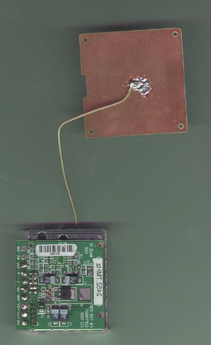
Rhein Tech Laboratories Client: Backgrounds Unlimited, Inc. 360 Herndon Parkway Model: TXBD1W Suite 1400 FCC ID: NH5-FWTX1W Herndon, VA 20170 Standards: FCC Part 90/IC RSS-210 http://www.rheintech.com Report Number: 2003073 36 of 46 APPENDIX K: EXTERNAL PHOTOGRAPHS PHOTOGRAPH 3: RF MODULE FRONT VIEW Rhein Tech Laboratories Client: Backgrounds Unlimited, Inc. 360 Herndon Parkway Model: TXBD1W Suite 1400 FCC ID: NH5-FWTX1W Herndon, VA 20170 Standards: FCC Part 90/IC RSS-210 http://www.rheintech.com Report Number: 2003073 37 of 46 PHOTOGRAPH 4: DETAILED EUT VIEW Ground Baseband Video Input +12V DC Input Baseband Right Audio Input Baseband Left Audio Input MIC Input – Not Used Rhein Tech Laboratories Client: Backgrounds Unlimited, Inc. 360 Herndon Parkway Model: TXBD1W Suite 1400 FCC ID: NH5-FWTX1W Herndon, VA 20170 Standards: FCC Part 90/IC RSS-210 http://www.rheintech.com Report Number: 2003073 38 of 46 PHOTOGRAPH 5: ANTENNA FRONT VIEW Rhein Tech Laboratories Client: Backgrounds Unlimited, Inc. 360 Herndon Parkway Model: TXBD1W Suite 1400 FCC ID: NH5-FWTX1W Herndon, VA 20170 Standards: FCC Part 90/IC RSS-210 http://www.rheintech.com Report Number: 2003073 39 of 46 PHOTOGRAPH 6: ANTENNA REAR VIEW
ID Label/Location Info
Rhein Tech Laboratories Client: Backgrounds Unlimited, Inc. 360 Herndon Parkway Model: TXBD1W Suite 1400 FCC ID: NH5-FWTX1W Herndon, VA 20170 Standards: FCC Part 90/IC RSS-210 http://www.rheintech.com Report Number: 2003073 29 of 46 APPENDIX E: LABEL INFORMATION Please refer to the following pages for a sample of the FCC ID label and a photograph of the label placement. FCC ID Label Model Number TXBD1W FCC ID Number: NH5-FWTX1W FCC ID: NH5-FWTX1W Backgrounds Unlimited, Inc. Model Number TXBD1W Tested under FCC Part 90 Regulations FCC ID: NH5-FWTX1W Backgrounds Unlimited, Inc. Model Number TXBD1W Tested under FCC Part 90 Regulations FCC ID Label shown at increased size FCC ID Label shown at actual size The FCC ID label will be placed on the heat sink of the production unit. Rhein Tech Laboratories Client: Backgrounds Unlimited, Inc. 360 Herndon Parkway Model: TXBD1W Suite 1400 FCC ID: NH5-FWTX1W Herndon, VA 20170 Standards: FCC Part 90/IC RSS-210 http://www.rheintech.com Report Number: 2003073 30 of 46 PHOTOGRAPH 1: FCC ID LABEL LOCATION FCC ID LABEL HERE
Internal Photos
Rhein Tech Laboratories Client: Backgrounds Unlimited, Inc. 360 Herndon Parkway Model: TXBD1W Suite 1400 FCC ID: NH5-FWTX1W Herndon, VA 20170 Standards: FCC Part 90/IC RSS-210 http://www.rheintech.com Report Number: 2003073 40 of 46 APPENDIX L: INTERNAL PHOTOGRAPHS PHOTOGRAPH 7: OVERALL INTERNAL VIEW Rhein Tech Laboratories Client: Backgrounds Unlimited, Inc. 360 Herndon Parkway Model: TXBD1W Suite 1400 FCC ID: NH5-FWTX1W Herndon, VA 20170 Standards: FCC Part 90/IC RSS-210 http://www.rheintech.com Report Number: 2003073 41 of 46 PHOTOGRAPH 8: PCB FRONT VIEW Rhein Tech Laboratories Client: Backgrounds Unlimited, Inc. 360 Herndon Parkway Model: TXBD1W Suite 1400 FCC ID: NH5-FWTX1W Herndon, VA 20170 Standards: FCC Part 90/IC RSS-210 http://www.rheintech.com Report Number: 2003073 42 of 46 PHOTOGRAPH 9: PCB REAR VIEW Rhein Tech Laboratories Client: Backgrounds Unlimited, Inc. 360 Herndon Parkway Model: TXBD1W Suite 1400 FCC ID: NH5-FWTX1W Herndon, VA 20170 Standards: FCC Part 90/IC RSS-210 http://www.rheintech.com Report Number: 2003073 43 of 46 PHOTOGRAPH 10: PCB2 FRONT VIEW Rhein Tech Laboratories Client: Backgrounds Unlimited, Inc. 360 Herndon Parkway Model: TXBD1W Suite 1400 FCC ID: NH5-FWTX1W Herndon, VA 20170 Standards: FCC Part 90/IC RSS-210 http://www.rheintech.com Report Number: 2003073 44 of 46 PHOTOGRAPH 11: PCB2 REAR VIEW Rhein Tech Laboratories Client: Backgrounds Unlimited, Inc. 360 Herndon Parkway Model: TXBD1W Suite 1400 FCC ID: NH5-FWTX1W Herndon, VA 20170 Standards: FCC Part 90/IC RSS-210 http://www.rheintech.com Report Number: 2003073 45 of 46 PHOTOGRAPH 12: PCB3 FRONT VIEW Rhein Tech Laboratories Client: Backgrounds Unlimited, Inc. 360 Herndon Parkway Model: TXBD1W Suite 1400 FCC ID: NH5-FWTX1W Herndon, VA 20170 Standards: FCC Part 90/IC RSS-210 http://www.rheintech.com Report Number: 2003073 46 of 46 PHOTOGRAPH 13: PCB3 REAR VIEW
RF Exposure Info
Rhein Tech Laboratories Client: Backgrounds Unlimited, Inc. 360 Herndon Parkway Model: TXBD1W Suite 1400 FCC ID: NH5-FWTX1W Herndon, VA 20170 Standards: FCC Part 90/IC RSS-210 http://www.rheintech.com Report Number: 2003073 25 of 46 APPENDIX A: FCC PART 1.1307, 1.1310, 2.1091, 2.1093: RF EXPOSURE From FCC 1.1310 Table 1A, the maximum permissible RF exposure for an uncontrolled environment is 1 mW/cm 2 . The Electric field generated for a 1 mW/cm 2 exposure (S) is calculated as follows: )4/()( 2 dGPS×××=π where: S = Power density P = Transmitter conducted power in watts G = Numeric gain d = distance to radiation center Fundamental Operating Frequency: 2463 MHz Maximum Rated Output Power: 1.0 Watts (1000 mW) Measured Maximum Output Power: 1.0 Watts (1000 mW) Antenna Gain = 6dBi; Numeric Gain = 3.98 S = (1000 X 3.98)/ (4 x Pi X 20 2 ) = 0.8 mW/cm 2 Under normal operating conditions, the antenna is designed to maintain a separation distance of 20 cm from all persons. The EUT is mobile and fixed. Calculated Power Density: Antenna Gain = 6dBi Conducted Power (milli-Watt) = 1000 Separation Distance = 20 cm FCC Power density Limit Calculated Power density at 20 cm distance 1 mW/cm 2 0.8 wW/cm 2
Test Report
Engineering and Testing for EMC and Safety Compliance T T Y Y P P E E C C E E R R T T I I F F I I C C A A T T I I O O N N R R E E P P O O R R T T FCC PART 90 Backgrounds Unlimited, Incorporated Old Town Hall, Rt. 11 South P.O. Box 327 Mt. Sidney, VA 24467 MODEL: TXBD1W FCC ID: NH5-FWVTX1W May 15, 2003 STANDARDS REFERENCED FOR THIS REPORT PART 2: 2001 FREQUENCY ALLOCATIONS AND RADIO TREATY MATTERS; GENERAL RULES AND REGULATIONS PART 15: 2001 RADIO FREQUENCY DEVICES - §15.109: RADIATED EMISSIONS LIMITS PART 90: 2001 PRIVATE LAND MOBILE RADIO SERVICES ANSI C63.4-1992 STANDARD FORMAT MEASUREMENT/TECHNICAL REPORT PERSONAL COMPUTER AND PERIPHERALS ANSI/TIA/EIA603- 1992 L AND MOBILE FM OR PM COMMUNICATIONS EQUIPMENT M EASUREMENT AND PERFORMANCE STANDARDS ANSI/TIA/EIA 603-1-1998 ADDENDUM TO ANSI/TIA/EIA 603-1992 ANSI/TIA/EIA –102.CAAA; 1999 DIGITAL C4FM/CQPSK TRANSCEIVER MEASUREMENT METHODS RSS-119; Issue 6; 2000 LAND MOBILE AND FIXED RADIO TRANSMITTERS AND RECEIVERS 27.41 TO 960.0 MHZ Frequency Range Output Power (W) Conducted Frequency Tolerance (ppm) Emission Designator 2463 MHz 1.0 26.77 16M5F3E REPORT PREPARED BY TEST ENGINEER: DAN BALTZELL Document Number: 2003073 / QRTL03-776 No part of this report may be reproduced without the full written approval of Rhein Tech Laboratories, Inc. Rhein Tech Laboratories Client: Backgrounds Unlimited, Inc. 360 Herndon Parkway Model: TXBD1W Suite 1400 FCC ID: NH5-FWTX1W Herndon, VA 20170 Standards: FCC Part 90/IC RSS-210 http://www.rheintech.com Report Number: 2003073 2 of 46 T ABLE OF CONTENTS 1 GENERAL INFORMATION....................................................................................................................................................................................5 1.1 TEST FACILITY ..........................................................................................................................................................................................................................5 1.2 RELATED SUBMITTAL(S)/GRANT(S).......................................................................................................................................................................................5 2 CONFORMANCE STATEMENT............................................................................................................................................................................6 3 TESTED SYSTEM DETAILS .................................................................................................................................................................................7 4 FCC RULES AND REGULATIONS PART 2 §2.1046 (A): RF POWER OUTPUT: CONDUCTED .......................................................................9 4.1 TEST PROCEDURE ...................................................................................................................................................................................................................9 4.2 TEST DATA ................................................................................................................................................................................................................................9 5 FCC RULES AND REGULATIONS PART 2 §2.1051: SPURIOUS EMISSIONS AT ANTENNA TERMINALS ..................................................10 5.1 TEST PROCEDURE .................................................................................................................................................................................................................10 5.2 TEST DATA ..............................................................................................................................................................................................................................10 6 FCC RULES AND REGULATIONS PART 2 §2.1053 (A): FIELD STRENGTH OF SPURIOUS RADIATION ....................................................11 6.1 TEST PROCEDURE .................................................................................................................................................................................................................11 6.2 TEST DATA ..............................................................................................................................................................................................................................12 6.2.1 CFR 47 PART 90.210 REQUIREMENTS.................................................................................................................................................................................12 7 FCC RULES AND REGULATIONS PART 2 §2.1049 (C) (1): OCCUPIED BANDWIDTH ..................................................................................14 7.1 TEST PROCEDURE .................................................................................................................................................................................................................14 7.2 EMISSION MASK B CALCULATION .......................................................................................................................................................................................15 7.3 TEST DATA ..............................................................................................................................................................................................................................16 7.4 TEST EQUIPMENT USED FOR TESTING ..............................................................................................................................................................................17 8 FCC RULES AND REGULATIONS PART 2 §2.202: NECESSARY BANDWIDTH AND EMISSION BANDWIDTH ........................................18 9 FCC RULES AND REGULATION PART 2 §2.1055: FREQUENCY STABILITY .....................................................................................…
Text truncated - open the document above for the full version.
Test Setup Photos
Rhein Tech Laboratories Client: Backgrounds Unlimited, Inc. 360 Herndon Parkway Model: TXBD1W Suite 1400 FCC ID: NH5-FWTX1W Herndon, VA 20170 Standards: FCC Part 90/IC RSS-210 http://www.rheintech.com Report Number: 2003073 35 of 46 APPENDIX J: TEST CONFIGURATION PHOTOGRAPHS PHOTOGRAPH 2: RADIATED EMISSIONS
Contact Information
Applicant
Thomas S Cline
Technical Contact
Rhein Tech LaboratoriesDesmond Fraser
[email protected]703-689-0368
360 Herndon Parkway · Herndon, Virginia · United States
Non-Technical Contact
Rhein Tech LaboratoriesKathy Grzovic
[email protected]703-689-0368
Test Firm
Rhein Tech Laboratories, Inc.Rick McMurray
Technical Specifications
| # | Rule Parts | Frequency Range | Power Output | Emission | Tolerance |
|---|---|---|---|---|---|
| 1 | 90 | 2.46 GHz - 2.46 GHz | 1 W | 16M5F3E | 26.8000000000 ppm |
Other Applications from Backgrounds Unlimited Inc
NH5FWVTXBD12A
Feb 29, 2000TXBD-12A
Equipment Class
TNB - Licensed Non-Broadcast Station Transmitter