NH5FWVTXBD12ATXBD-12A
Backgrounds Unlimited Inc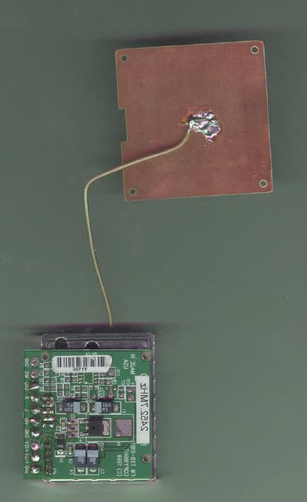
Click to zoom
Application Details
- Equipment Class
- TNB - Licensed Non-Broadcast Station Transmitter
- Date of Grant
- Feb 29, 2000
- Application Purpose
- Original Equipment
- Date of Application
- Nov 29, 1999
- Equipment Note
- TXBD-12A
- Frequency Range
- 2452.70000000 - 2472.70000000
- Company
- Backgrounds Unlimited Inc
- Country
- United States
Documents & Files
Document Text
Text extracted from the exhibit documents filed with the FCC. Open a document above to read the original.
Users Manual
PRELIMINARY MANUAL Backgrounds Unlimited, Incorporated. Old Town Hall, Rt. 11 South P.O. Box 327 Mt. Sidney, VA 24467 MODEL: TXBD-12A FCC ID: NH5FWVTXBD12A VCR or Satellite Receiver or Camcorder or Setting Up Units Using absolutely no wires, Backgrounds Unlimited TXBD12A and can send audio or video signals from virtually any sound or picture source to any TV, video monitor or powered speakers using the same connectors as your other electronics. To enjoy wireless video and audio, just connect the transmitter to whatever picture or sound source you want to view or hear at another location, and then connect the receiver to the TV, computer, or powered speakers in that other location. Then turn on the power switch on both the transmitter and receiver and you are ready to go wireless. Stereo Receiver Send from any of -the following sources: Video Audio Power Speakers • VCR Compact Disc Player or Changer • Satellite Receiver Stereo Receiver • Cable TV Cassette Deck • Laser Disc Player • Digital Video Disc • Wireless Cable • Camcorder • Security Camera (CCD) • Computer The following pages first show you how to connect the Backgrounds Unlimited TXBD11A transmitter to any of these source components and then demonstrate how and where to connect and position the receiver. TXBD12A Transmitter Receiver TV & Monitor or 4 Locate and orient the transmitter according to the section of this manual titled "Orienting Units for Optimal Performance.' BACKGROUNDS UNLIMITED, TXBD12A TRANSMITTER Connecting the Transmitter How To Transmit Audio/Video from Your VCR 1 Make sure the Backgrounds Unlimited TXBD12A Transmitter ON/OFF switch is in the OFF position. Connect one set of audio/video (A/V) cables to the A/V jacks of the transmitter and to the A/V jacks on the back of your VCR labeled LINE OUT. Be sure the yellow, red and white plugs match the yellow, red and white jacks on both the VCR and the transmitter. If the VCR has only one output for audio (mono sound only), connect the white plug to that single audio output and to transmitter's AUDIO LEFT jack. 2 Plug one end of the provided power adapter into the back of the Backgrounds Unlimited TXBD12A transmitter and the other end into any 120-volt wall outlet. Turn the ON/OFF switch to ON position and channel 1 indicator light should be lit. 3 If your VCR has only one set of A/V output jacks and you want to use it with a nearby TV, connect coaxial cable from the single OUT port on your VCR to the VHF/UHF IN port on your TV. (Note: In order to also view cable transmission on that TV, connect your incoming cable TV source to the single IN port of the VCR.)
Users Manual
USER’S MANUAL Ultralink Video Transmitter Model Number: TXBD12A FCC ID NUMBER: NH5FWVTXBD12A Backgrounds Unlimited, Inc. P.O. Box 327 Mt. Sidney, VA 24467 (540) 248-0355 (540) 248-0920 fax [email protected] Description and Applications of the System The Ultralink Video Transmitter (Model TXBD12A) is a long range video transmitter intended for Government or Law Enforcement use. The unit can be set up within a matter of minutes and will transmit clear black and white or color video to the receiver. The TXBD12A accepts input from an NTSC baseband video source, typically a camera. The TXBD12A is supplied with the following: (1) Ultralink Video Transmitter (1) Receiver (2) 12Vdc, 500ma power supplies (1) RCA Cable for Video out on receiver The TXBD12A is perfect for: • Drug investigations • Trouble spots where Law Enforcement Personnel need to see without being on sight • Traffic observations • Sting operations • Landfill areas • OR any area where running of cable is too costly Deployment of the System 1) Using the provided 12Vdc power supply, connect the 12Vdc Positive lead to the Power input pad of the board. 2) Next connect the 12Vdc Negative lead to ground. 3) If you are using a 12Vdc camera, you may connect the camera's power lead to the 12Vdc Positive lead and ground. Also connect the Video + to the Video pad (see figure 1). 4) For best range, direct the antenna in the general direction of your receiver. figure 1 Viewing the Video 1) After setting up the video transmitter, connect the receiver to the second provided 12Vdc power supply. 2) Orient the directional antenna towards the transmitter. 3) From the Video Out on the receiver, connect to any video input for recording or viewing. Special Notice Although the TXBD12A is very simple to use, the Video Transmitter is a high end video transmitter. Special care should be taken when in use. Before using the item the FCC wants you to know the following: This equipment may only be operated under a Part 90 station license issued by the FCC for Business, Industrial or Public Safety purposes. The user is responsible for operating this equipment in compliance with FCC Rules. Operation of this equipment without a valid FCC License could result in the issuance of fines to the user or seizure of the equipment. Any changes or modifications to this equipment without the express authorization of the manufacturer could void the user's authority to operate this equipment. FCC ID Number: NH5FWVTXBD12A Always make sure your equipment is legal and has a valid FCC ID Number. If this item is purchased by a Law Enforcement Department, your communications officer can contact the FCC for the proper paperwork.
Block Diagram
APPENDIX B: BLOCK DIAGRAM / SCHEMATICS OF THE TXBD-12A
ID Label/Location Info
2.0PRODUCT LABELING FIGURE 1: FCC ID LABEL FIGURE 2: LOCATION OF LABEL ON EUT BACK OF EUT Label Placement Backgrounds Unlimited, Incorporated TXBD-12A FCC ID: NH5FWVTXBD12A
Internal Photos
7.0PHOTOS OF TESTED EUT FIGURE 14: FRONT OF EUT FIGURE 15: BACK OF EUT FIGURE 16: TOP INSIDE BRACKET FIGURE 17: TOP OUTSIDE BRACKET FIGURE 18: BOTTOM PCB BOTTOM SIDE FIGURE 19: BOTTOM PCB TOP SIDE FIGURE 20: BOTTOM SIDE OF TOP PCB FIGURE 21: COMPONENT SIDE OF TOP PCB
Test Report
EMC COMPLIANCE ENGINEERING AND TESTING Accredited 360 Herndon Parkway, Suite 1400 Herndon,VA 20170 703 689-0368 FAX 703 689-2056 ÕÕÕÕÕÕÕÕÕÕÕÕÕÕÕÕÕÕÕÕÕÕÕÕÕÕÕÕÕÕÕÕÕÕÕÕÕÕÕÕÕÕÕÕÕÕÕ APPLICATION FOR PART 90 CERTIFICATION TRANSMITTER Backgrounds Unlimited, Incorporated Old Town Hall, Rt. 11 South P.O. Box 327 Mt. Sidney, VA 24467 MODEL: TXBD-12A FCC ID: NH5FWVTXBD12A November 22, 1999 REPORT PREPARED BY: EMI Technician:Daniel W. Baltzell Administrative Writer:Melissa Fleming Rhein Tech Laboratories, Inc. Document Number: 990484 No part of this report may be reproduced without the full written approval of Rhein Tech Laboratories, Inc. This report concerns (check one):Original Grant: X Class II Change: Equipment Type: Transmitter Deferred grant requested per 47 CFR 0.457 (d) (1) (ii)?Yes:No: X If yes, defer until: Date Company name agrees to notify the Commission by: (date) of the intended date of announcement of the product so that the grant can be issued on that date. FCC ID:NH5FWVTXBD12A Work Order Number:990484 EUT:TXBD-12A Page 1 of 38 TABLE OF CONTENTS 1.0GENERAL INFORMATION.................................................................................................................3 1.1PRODUCT DESCRIPTION..........................................................................................................................3 1.2RELATED SUBMITTAL(S)/GRANT(S)........................................................................................................3 1.3TEST SYSTEM DETAILS...........................................................................................................................4 1.4CONFIGURATION OF TESTED SYSTEM......................................................................................................4 2.0PRODUCT LABELING.........................................................................................................................5 3.0SYSTEM TEST CONFIGURATION....................................................................................................6 3.1JUSTIFICATION.......................................................................................................................................6 3.2EUT EXERCISE SOFTWARE.....................................................................................................................6 3.3CONFORMANCE STATEMENT...................................................................................................................6 4.0STANDARD REQUIREMENTS............................................................................................................7 4.1FCC PART 90.211(C) AND PART 2.987: MODULATION REQUIREMENTS AND CHARACTERISTICS...............7 4.1.1FCC Part 2.987(a): Audio Frequency Response...........................................................................7 4.1.1.1Method of Measurement............................................................................................................................7 4.1.1.2Test Results..............................................................................................................................................7 4.2FCC PART 2.989(B) OCCUPIED BANBWIDTH PER ANSI C63.4 SECTION 13.1.7.................................8 4.3FCC PART 90.205(L) AND PART 2.985....................................................................................................9 4.2.1RF Power Output (ERP):...............................................................................................................9 4.2.2Method of Measurement................................................................................................................9 4.4FCC PART 90.207: TYPE OF EMISSIONS - EMISSION DESIGNATOR..........................................................10 4.5FCC PART 2.997(A)(1): FREQUENCY SPECTRUM TO BE INVESTIGATED..................................................10 4.6FCC PART 90.210(B) AND PART 2.991: EMISSION MASKS AND SPURIOUS EMISSIONS AT ANTENNA TERMINAL.......................................................................................................................................................10 4.6.1Method of Measurement..............................................................................................................10 4.7FCC PART 90.210 (B)(1)(2)(3)............................................................................................................11 4.8FCC PART 2.993: FIELD STRENGTH OF SPURIOUS RADIATION...............................................................11 4.8.1Method of Measurement..............................................................................................................11 4.9FCC PART 90.213 AND PART 2.995(A): FREQUENCY STABILITY AS A FUNCTION OF TEMPERATURE........11 4.9.1Method of Measurement..............................................................................................................11 4.9.2Minimum Frequency stability (ppm)............................................................................................11 5.0 MEASUREMENT PLOTS.........................................................................................................................13 5.1MEASUREMENT PLOTS FCC PART 90.210 (B) / PART 2.993...................................................................13 5.2FCC PART 2.993: FIELD STRENGTH OF SPURIOUS RADIATION................................................................22 5.3RADIATED MEASUREMENT PHOTOS......................................................................................................23 5.4CONDUCTED EMISSIONS.......................................................................................................................24 5.5CONDUCTED MEASUREMENT PHOTOS...................................................................................................26 5.6FREQUENCY STABILITY FUNCTION OF TEMPERATURE..............................................................................27 6…
Text truncated - open the document above for the full version.
Test Setup Photos
5.3RADIATED MEASUREMENT PHOTOS 5.5CONDUCTED MEASUREMENT PHOTOS
Contact Information
Applicant
Thomas S Cline
Technical Contact
Rhein Tech Laboratories, Inc.Desmond A Fraser
[email protected]703-689-0368
360 Herndon Parkway · Herndon, Virginia · United States
Non-Technical Contact
Rhein Tech Laboratories, Inc.Melissa Fleming
[email protected]703-689-0368
Technical Specifications
| # | Rule Parts | Frequency Range | Power Output | Emission | Tolerance |
|---|---|---|---|---|---|
| 1 | 90 | 2.45 GHz - 2.47 GHz | 100.00 mW | 10M6F3F | 0.0064000000 % |
Other Applications from Backgrounds Unlimited Inc

NH5-FWTX1W
Jun 22, 2003Ultralink Video Transmitter
Equipment Class
TNB - Licensed Non-Broadcast Station Transmitter