NHVWBU614Passive Entry System
Tohoku Alps Co Ltd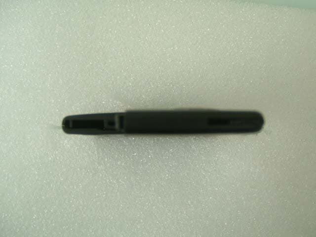
Click to zoom
Application Details
- Equipment Class
- DSR - Part 15 Remote Control/Security Device Transceiver
- Date of Grant
- Jun 19, 2003
- Application Purpose
- Original Equipment
- Date of Application
- Jun 19, 2003
- Equipment Note
- Passive Entry System
- Frequency Range
- 433.92000000 - 433.92000000
- Company
- Tohoku Alps Co Ltd
- Country
- Japan
Documents & Files
Document Text
Text extracted from the exhibit documents filed with the FCC. Open a document above to read the original.
Users Manual
ALPS ELECTRIC Co., LTD CONTENTS 1. PREFACE 2. PASSSIVE ACCSESS ENTRY FUNCTIONALITY 2.1. Door Unlocking 2.2. Engine Start 2.3. Engine Stop 2.4. Door Locking (Push switch) 3. ACTIVE ACCESS ENTRY FUNCTIONALITY 3.1. Door Unlocking 3.2. Engine Start 3.3. Engine Stop 3.4. Door Locking 4. ENTRY SYSTEM OPTIONS 4.1. System Schematic 4.2. Modules 4.2.1. FOB ECU 4.2.2. Entry System ECU 5. SYSTEM CHARACTERISTICS 5.1. Antenna Areas 5.2. Exciter Locations 5.3. Switch Input Locations (Door handle, Touch sensor) 6. ELECTRICAL CHARACTERISTICS 6.1. FOB 6.2. Entry System ECU FCC WARNING NOTICE ALPS ELECTRIC Co., LTD 1.Preface This document describes the requirements and operation of the Passive Entry System. However, this document is especially for the Entry system ECU (acronym for Electric Control Unit) and the FOB. The FOB consists the following functionality for passive access and active access: • Door unlocking / locking (however, only for request by means of switch operation) • Trunk unlocking / locking (however, only for request by means of switch operation) • LF decoding • RF encoding • Communication data encryption (cryptograph, anti-collision, rolling code and stuff) And the entry system ECU consists of the following functionality: • Door unlocking / locking • Trunk unlocking / locking • Engine start (/ stop) • LF encoding • RF encoding • Communication data encryption (cryptograph, anti-collision, rolling code and stuff) • LF antenna unit control • Communication with the node ECUs connected to the body bus (e.g. CAN, J1850, customer dependent bus) As a further function, both the FOB and the entry system ECU provides the following function: • Learning mode for programming the manufacturing data and stuff • Data locking and password protection • Diagnostic (based upon ISO9141 if required) ALPS ELECTRIC Co., LTD 2.Passsive Accsess Entry Functionality A proximity sensor located on, for example the door handles, mirrors and trunk lid will be used for proximity check if user is in neighborhood of the vehicle. The switch input will trigger for unlocking and open the doors and trunk. Figure 1 2.1.Door Unlocking • User pull / touch the door handle (sensing of door handle switch). • ECU sends LF-challenge via exterior antenna. • FOB sends RF-response to the ECU. • Door unlocking status is engaged. • Doors are opened. Figure 2 Proximity sensor LF RF FOB ALPS ELECTRIC Co., LTD 2.2.Engine Start • User pushes / operate the engine start button / knob. • ECU sends LF-challenge via interior antenna. • FOB sends RF-response to the ECU. • Immobilizer ECU receives and authorize the response. • Engine controller ECU receives the authorization for engine strat. • Start the engine. Figure 3 2.3.Engine Stop • User pushes / operate the engine stop button / knob. • ECU communicates with the other ECU for engine start request. • Engine controller ECU receives the request. • Stop the engine Figure 4 LF RF FOB ALPS ELECTRIC Co., LTD 2.4.Door Locking (Push switch) • User closes the door and pushes the switch (sensing of door locking switch). • ECU sends LF-challenge via exterior antenna. • FOB sends RF-response to the ECU. • Door locking status is engaged. • Doors are locked. • (Indicates the door locking status by means of Flasher / Buzzer or stuff) Figure 5 ALPS ELECTRIC Co., LTD 3.Active Access Entry Functionality 3.1.Door Unlocking Same functionality as the current one. 3.2.Engine Start This function does not effect on the active entry system. 3.3.Engine Stop This function does not have influencei on the active entry system. 3.4.Door Locking Same functionality as the current one. ALPS ELECTRIC Co., LTD 4.Entry System Options 4.1.System Schematic 4.2.Modules 4.2.1.FOB ECU 4.2.2.Entry System ECU OTHER ECUS LF (>2Kbps) RF (>4Kbps) Local Bus ECU1 ECU2 ECU3 Body Bus ENTRY SYSTEM ECU FOB 125kHz 433.92 MHz FOB RF Amp LF Amp ASIC Z X Y Lock Unlock Trunk Key lock Emergency key (Transponder) 125kHz 433.92 MHz ENTRY SYSTEM ECU MCU FT handle BT handle FH handle BH handle Trunk lid Engine start Body Bus Local Bus RF Amp LF Exciter LF Exciter LF Exciter LF Exciter LF Exciter LF Exciter Interior FT BT FH BH Trunk 433.92 MHz 125kHz ALPS ELECTRIC Co., LTD 5.System Characteristics 5.1.Antenna Areas Exterior operating range: 0.8m to 1.5m Interior operating range: Only inside the car Number of the exterior exciters : max. 5 (min. 2), however, it is depending on the type of the vehicle. Number of the interior exciters: 1 (1-Dimmension) or 2 (2-Dimension required) Figure 6 Exterior antenna functionality: • Unlock / lock doors and trunk. • Activate / deactivate alarm system. • Activate immobilizer Interior antenna functionality: • Deactivate immobilizer • Engine start Exterior Interior FT BT ALPS ELECTRIC Co., LTD 5.2.Exciter Locations Exterior exciters: 2 doors and 1 trunk Interior exciters: 1 driver’s sheet 2 column / shift lever (X-Y 2-Dimension) Figure 7 Antenna location can be different among of type of the vehicle (e.g. coupe, sedan, mini and stuff). Exterior Interior FT BT ALPS ELECTRIC Co., LTD 5.3.Switch Input Locations (Door handle, Touch sensor) There are some kind of sensors, for instance the door handle contact switch and touch sensor, will be used as a triggering for unlocking and open the door. Switch inputs: 2 doors and 1 trunk Figure 8 Switch inputs can be different among of type of the vehicle (e.g. coupe, sedan, mini and stuff). FT BT ALPS ELECTRIC Co., LTD 6.Electrical Characteristics 6.1.FOB • ASK / FSK modulation • Operating supply voltage 2.1V to 4.0V (3.0V Battery) • Operating supply current < 7mA • Stand-by current < 10.0uA • Operating ambient temperature -20 o C to +60 o C • Antenna direction 3-Dimension (X, Y, Z), to be considered • Battery life 2 Years (Low battery indication is considered) 6.2.Entry System ECU • Operating supply voltage 10.5V to 16.0V • Operating supply current < 15mA (20mA to 30mA) • Stand-by current < 4mA • Operating ambient temperature -40 o C to +85 o C • ALPS ELECTRIC Co., LTD FCC WARNING Change…
Text truncated - open the document above for the full version.
Cover Letter(s)
American Telecommunications Certification Body Inc. 6731 Whittier Ave, McLean, VA 22101 June 16, 2003 RE: FCC ID: NHVWBU614 Attention: Yukari Ito / Yoshiaki Iwasa I have a few comments on this Application. 1. Please note that the device is not compliant with the rules and therefore fails. Please note the readings on page 14 of the report. The Fundamental has a measured peak reading of 45.4dBuV/m horizontal and yet 3905 MHz has a peak reading of 45.6dBuV/m. It is not just the spurious emissions limits (average and peak) that must be met, but the requirement that “ the level of any unwanted emissions shall not exceed the level of the fundamental frequency.” (see 15.209c). Please note that this is not a ‘limit’ measurement, but a comparative measurement to the fundamental level. If this were a non-harmonic emission, there may be some argument about the average limit, however, since this is a harmonic, this frequency fails. Please provide data showing that no harmonic exceeds the fundamental. 2. Please verify that the 434 Mhz signal on page 15 of the report is not the same signal as the fundamental frequency on page 14 of the report. Dennis Ward mailto:[email protected] The items indicated above must be submitted before processing can continue on the above referenced application. Failure to provide the requested information may result in application termination. Correspondence should be considered part of the permanent submission and may be viewed from the Internet after a Grant of Equipment Authorization is issued. Please do not respond to this correspondence using the email reply button. In order for your response to be processed expeditiously, you must submit your documents through the AmericanTCB.com website. Also, please note that partial responses increase processing time and should not be submitted. Any questions about the content of this correspondence should be directed to the sender.
Cover Letter(s)
June 20, 2003 RE: TOHOKU ALPS CO., LTD. FCC ID: NHVWBU614 Dear Mr. Dennis Ward, Regarding the above referenced application, please find our reply to the comments dated June 16, 2003: 1) Some of original data shows the data of noise floor of the measurement system. After improvement of the measurement system, re-measurement was carried out. Please see the submitted revised data of page 14. 2) 434MHz signal on page 15 is not the same signal as the fundamental frequency on page 14 of the report. 210MHz, 434MHz, and 867.84MHz signals show data of noise floor of the measurement system, because FCC requests to report at least 6 measurement data in accordance with ANSI C63.4. We hope the above reply is satisfactory. If any problems, please let us know. Best regards, Yukari Ito (Ms.) UL Apex Co., Ltd.
External Photos
Tohoku Alps Co., Ltd. FCC ID: NHVWBU614 External Photo Front Rear Tohoku Alps Co., Ltd. FCC ID: NHVWBU614 Top Bottom Tohoku Alps Co., Ltd. FCC ID: NHVWBU614 Right Left
Internal Photos
Tohoku Alps Co., Ltd. FCC ID: NHVWBU614 Internal Photo Side A Tohoku Alps Co., Ltd. FCC ID: NHVWBU614 Tohoku Alps Co., Ltd. FCC ID: NHVWBU614 Side B
Contact Information
Applicant
Tom Takata
81 229 233111Fax: 81 229 229997
Technical Contact
UL Apex Co., Ltd.Yoshiaki Iwasa
[email protected]81-596-24-8116
4383-326 Asama-cho, · Ise-shi, Mie-ken · Japan
Test Firm
UL Apex Co., Ltd.Toshihiro Ikegami
Technical Specifications
| # | Rule Parts | Frequency Range | Power Output |
|---|---|---|---|
| 1 | 15.231 | 433.92 MHz - 433.92 MHz | - |
Other Applications from Tohoku Alps Co Ltd
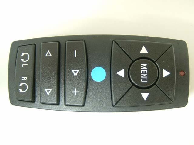
NHVWZU11
Jul 08, 2003Remote Control for the Vehicle
Equipment Class
DSC - Part 15 Security/Remote Control Transmitter
NHVWBU613
Jun 19, 2003Passive Entry System
Equipment Class
DSR - Part 15 Remote Control/Security Device Transceiver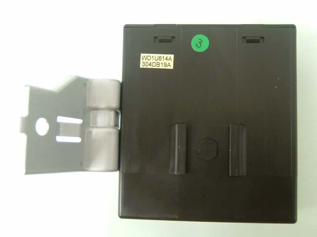
NHVWDU614
Jun 16, 2003Passive Entry System
Equipment Class
DCD - Part 15 Low Power Transmitter Below 1705 kHz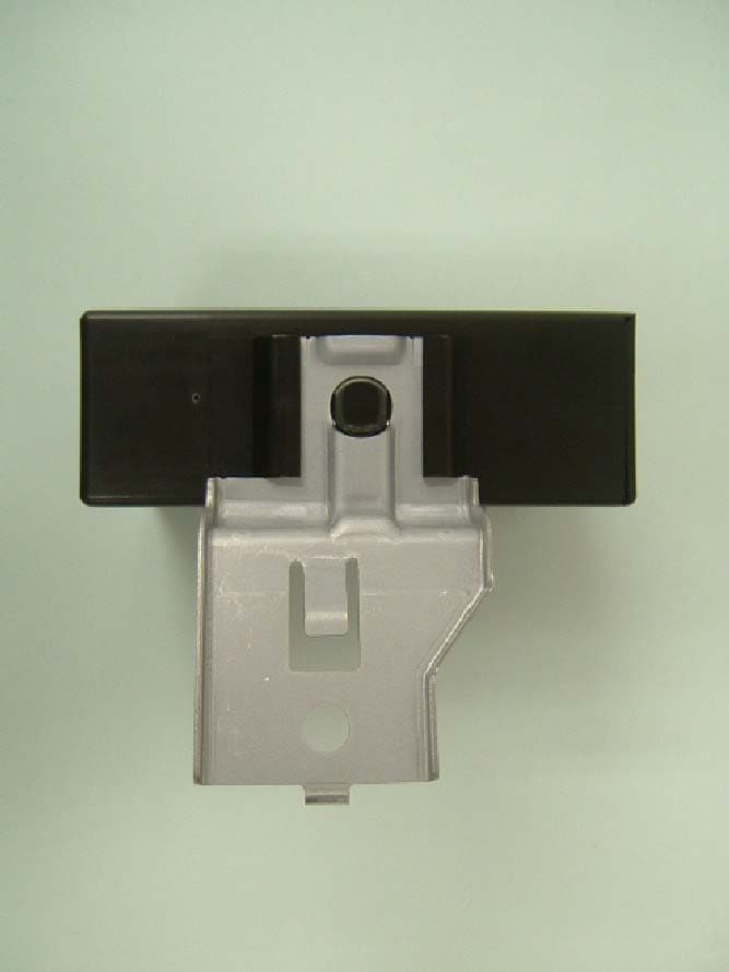
NHVWDU613
Jun 11, 2003Passive Entry System
Equipment Class
DCD - Part 15 Low Power Transmitter Below 1705 kHz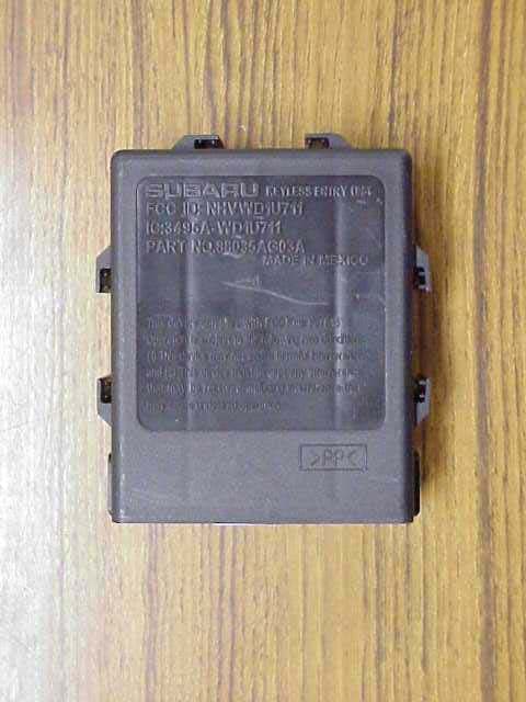
NHVWD1U711
Apr 01, 2003Keyless Entry System Receiver
Equipment Class
CYY - Communications Receiver used w/Pt 15 Transmitter