NHVWDU614Passive Entry System
Tohoku Alps Co Ltd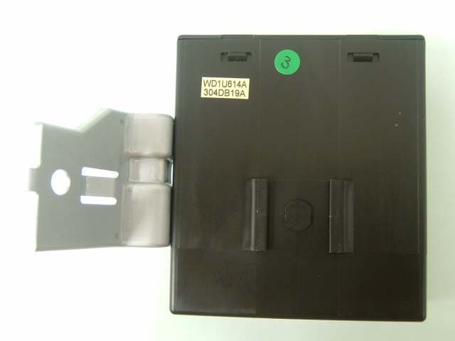
Click to zoom
Application Details
- Equipment Class
- DCD - Part 15 Low Power Transmitter Below 1705 kHz
- Date of Grant
- Jun 16, 2003
- Application Purpose
- Original Equipment
- Date of Application
- Jun 16, 2003
- Equipment Note
- Passive Entry System
- Frequency Range
- 0.12500000 - 0.12500000
- Company
- Tohoku Alps Co Ltd
- Country
- Japan
Documents & Files
Document Text
Text extracted from the exhibit documents filed with the FCC. Open a document above to read the original.
Users Manual
ALPS ELECTRIC Co., LTD CONTENTS 1. PREFACE 2. PASSSIVE ACCSESS ENTRY FUNCTIONALITY 2.1. Door Unlocking 2.2. Engine Start 2.3. Engine Stop 2.4. Door Locking (Push switch) 3. ACTIVE ACCESS ENTRY FUNCTIONALITY 3.1. Door Unlocking 3.2. Engine Start 3.3. Engine Stop 3.4. Door Locking 4. ENTRY SYSTEM OPTIONS 4.1. System Schematic 4.2. Modules 4.2.1. FOB ECU 4.2.2. Entry System ECU 5. SYSTEM CHARACTERISTICS 5.1. Antenna Areas 5.2. Exciter Locations 5.3. Switch Input Locations (Door handle, Touch sensor) 6. ELECTRICAL CHARACTERISTICS 6.1. FOB 6.2. Entry System ECU FCC WARNING NOTICE ALPS ELECTRIC Co., LTD 1.Preface This document describes the requirements and operation of the Passive Entry System. However, this document is especially for the Entry system ECU (acronym for Electric Control Unit) and the FOB. The FOB consists the following functionality for passive access and active access: • Door unlocking / locking (however, only for request by means of switch operation) • Trunk unlocking / locking (however, only for request by means of switch operation) • LF decoding • RF encoding • Communication data encryption (cryptograph, anti-collision, rolling code and stuff) And the entry system ECU consists of the following functionality: • Door unlocking / locking • Trunk unlocking / locking • Engine start (/ stop) • LF encoding • RF encoding • Communication data encryption (cryptograph, anti-collision, rolling code and stuff) • LF antenna unit control • Communication with the node ECUs connected to the body bus (e.g. CAN, J1850, customer dependent bus) As a further function, both the FOB and the entry system ECU provides the following function: • Learning mode for programming the manufacturing data and stuff • Data locking and password protection • Diagnostic (based upon ISO9141 if required) ALPS ELECTRIC Co., LTD 2.Passsive Accsess Entry Functionality A proximity sensor located on, for example the door handles, mirrors and trunk lid will be used for proximity check if user is in neighborhood of the vehicle. The switch input will trigger for unlocking and open the doors and trunk. Figure 1 2.1.Door Unlocking • User pull / touch the door handle (sensing of door handle switch). • ECU sends LF-challenge via exterior antenna. • FOB sends RF-response to the ECU. • Door unlocking status is engaged. • Doors are opened. Figure 2 Proximity sensor LF RF FOB ALPS ELECTRIC Co., LTD 2.2.Engine Start • User pushes / operate the engine start button / knob. • ECU sends LF-challenge via interior antenna. • FOB sends RF-response to the ECU. • Immobilizer ECU receives and authorize the response. • Engine controller ECU receives the authorization for engine strat. • Start the engine. Figure 3 2.3.Engine Stop • User pushes / operate the engine stop button / knob. • ECU communicates with the other ECU for engine start request. • Engine controller ECU receives the request. • Stop the engine Figure 4 LF RF FOB ALPS ELECTRIC Co., LTD 2.4.Door Locking (Push switch) • User closes the door and pushes the switch (sensing of door locking switch). • ECU sends LF-challenge via exterior antenna. • FOB sends RF-response to the ECU. • Door locking status is engaged. • Doors are locked. • (Indicates the door locking status by means of Flasher / Buzzer or stuff) Figure 5 ALPS ELECTRIC Co., LTD 3.Active Access Entry Functionality 3.1.Door Unlocking Same functionality as the current one. 3.2.Engine Start This function does not effect on the active entry system. 3.3.Engine Stop This function does not have influencei on the active entry system. 3.4.Door Locking Same functionality as the current one. ALPS ELECTRIC Co., LTD 4.Entry System Options 4.1.System Schematic 4.2.Modules 4.2.1.FOB ECU 4.2.2.Entry System ECU OTHER ECUS LF (>2Kbps) RF (>4Kbps) Local Bus ECU1 ECU2 ECU3 Body Bus ENTRY SYSTEM ECU FOB 125kHz 433.92 MHz FOB RF Amp LF Amp ASIC Z X Y Lock Unlock Trunk Key lock Emergency key (Transponder) 125kHz 433.92 MHz ENTRY SYSTEM ECU MCU FT handle BT handle FH handle BH handle Trunk lid Engine start Body Bus Local Bus RF Amp LF Exciter LF Exciter LF Exciter LF Exciter LF Exciter LF Exciter Interior FT BT FH BH Trunk 433.92 MHz 125kHz ALPS ELECTRIC Co., LTD 5.System Characteristics 5.1.Antenna Areas Exterior operating range: 0.8m to 1.5m Interior operating range: Only inside the car Number of the exterior exciters : max. 5 (min. 2), however, it is depending on the type of the vehicle. Number of the interior exciters: 1 (1-Dimmension) or 2 (2-Dimension required) Figure 6 Exterior antenna functionality: • Unlock / lock doors and trunk. • Activate / deactivate alarm system. • Activate immobilizer Interior antenna functionality: • Deactivate immobilizer • Engine start Exterior Interior FT BT ALPS ELECTRIC Co., LTD 5.2.Exciter Locations Exterior exciters: 2 doors and 1 trunk Interior exciters: 1 driver’s sheet 2 column / shift lever (X-Y 2-Dimension) Figure 7 Antenna location can be different among of type of the vehicle (e.g. coupe, sedan, mini and stuff). Exterior Interior FT BT ALPS ELECTRIC Co., LTD 5.3.Switch Input Locations (Door handle, Touch sensor) There are some kind of sensors, for instance the door handle contact switch and touch sensor, will be used as a triggering for unlocking and open the door. Switch inputs: 2 doors and 1 trunk Figure 8 Switch inputs can be different among of type of the vehicle (e.g. coupe, sedan, mini and stuff). FT BT ALPS ELECTRIC Co., LTD 6.Electrical Characteristics 6.1.FOB • ASK / FSK modulation • Operating supply voltage 2.1V to 4.0V (3.0V Battery) • Operating supply current < 7mA • Stand-by current < 10.0uA • Operating ambient temperature -20 o C to +60 o C • Antenna direction 3-Dimension (X, Y, Z), to be considered • Battery life 2 Years (Low battery indication is considered) 6.2.Entry System ECU • Operating supply voltage 10.5V to 16.0V • Operating supply current < 15mA (20mA to 30mA) • Stand-by current < 4mA • Operating ambient temperature -40 o C to +85 o C • ALPS ELECTRIC Co., LTD FCC WARNING Change…
Text truncated - open the document above for the full version.
External Photos
Tohoku Alps Co., Ltd. FCC ID: NHVWDU614 External Photo Front Rear Tohoku Alps Co., Ltd. FCC ID: NHVWDU614 Top Bottom Tohoku Alps Co., Ltd. FCC ID: NHVWDU614 Right Left
Internal Photos
Tohoku Alps Co., Ltd. FCC ID: NHVWDU614 Internal Photo Tohoku Alps Co., Ltd. FCC ID: NHVWDU614
Operational Description
ALPS ELECTRIC Co., LTD 1. System block diagram MMMM Dr As Rr Rl Dr door ANT I-KEY C/U Room ANT 1 Dr request SW Key SW Push SW IGN SW MATER STRG LOCK UNIT As door ANT As request SW Trunk request B/D ANT Dr state SW CAN Hi CAN Lo ACC SW Dr buzzer 5V GND SIG Trunk Room ANT BCM M Trunk IMMOBI ANT USM ECCS Trunk buzzer ALPS ELECTRIC Co., LTD 2. Connector & Terminal No. 3. CASE SIZE 21 3 4 5 6 7 8 91011121314151617181920 2221 23 24 25 26 27 28 29 30 31 32 33 34 35 36 37 38 39 40 TH40HW Terminal No.Terminal Name Terminal No.Terminal Name 1STRG LOCK 5V OUTPUT 21 NC 2CAN Hi 22 (KEY LO CK SOL for MT) 3CAN Lo 23 Trunk BUZZER OUTPUT 4Dr BUZZER OUTPUT 24 (BCM) 5Dr request SW 25 ASST request SW 6IGN SW 26 (STOP LAM P SW OPT) 7 KEY SW 27 PUSH SW 8(Key rotate SW) 28 Dr LO CK STATE SW 9(Low Input SW (OPT)) 29 BACK DOOR request SW 10 ACC SW 30 (BAT) 11 BAT 31 STRG GND 12 GND 32 STRG LO CK UNIT SIG 13 LUGGAGE ANT +33(LUGGAGE ANT +(OPT)) 14 LUGGAGE ANT -34(LUGGAGE ANT -(OPT)) 15 RO O M ANT1+ 35 ROOM ANT2+ 16 RO O M ANT1- 36 ROOM ANT2- 17 BACK DOOR ANT+ 37 ASST DOOR ANT+ 18 BACK DOOR ANT- 38 ASST DOOR ANT- 1 9Dr DOOR ANT+ 39 (Hi Input SW (OPT)) 20 Dr DOOR ANT- 40 NC 32m m max3mm max3mm 80m m 100m m connector ALPS ELECTRIC Co., LTD 4.Function 1.Entry Function 1-1.Operation by request SW (W hen the custom er setting state is "SELECTIVE UNLO CK"="0") (1)Door lock state of each door i-key unit has 3 state of door lock state,"lock state"or"ready to all door unlock"or"unlock state" for Each door independently Each door's door lock state is defined following state chart *1 W hen i-key unit received can com m and"dr door actr info"="10" or "other door actr info"="10" from BCM, I-key unit recognize BCM m akes all doors lock *2 W hen I-key unit received can com m and"other door actr info"="01" from BCM, I-key unit recognize BCM m akes all doors unlock @ (2)Operation by request SW door lock state*3 Output when the request SW is operated lock state operated door's select unlock output ready to all door unlock all door unlock output unlock state lock output *3 "door lock state" of which that request SW operated 1-2.Operation by request SW (W hen the custom er setting state is "SELECTIVE UNLO CK"="1") (1)Door lock state of each door i-key unit has 2 state of door lock state,"lock state"or"unlock" for all door door lock state is defined following state chart *1 W hen i-key unit received can com m and"dr door actr info"="10" or "other door actr info"="10" from BCM, I-key unit recognize BCM m akes all doors lock *2 W hen I-key unit received can com m and"other door actr info"="01" from BCM, I-key recognize BCM makes all doors unlock (2)Operation by request SW door lock state Output when the request SW is operated lock state all door unlock output unlock state lock output Dr Door lock state ready to all door unlock unlock state Estart to Dr door select unlock operation by "operation of the unlock button of I-key"or "operation of the Dr request sw" EBCM makes all doors lock *1 EBCM m akes all doors unlock *2 @(except ASST door select unlock output) Eafter 5sec from the Dr door's door lock state becam e "ready to all door unlock"from "lock EBCM m akes all doors unlock @*2 EAny door which door lock state is "lock state" close ̈open ERR @door or RL door close ̈ @open EBCM m akes all doors lock *1 Asst Door lock state ready to all door unlock unlock state Estart to Asst door select unlock operation by "operation of the Asst request sw" EBCM makes all doors lock *1 EBCM m akes all doors unlock *2 Eafter 5sec from the Asst door's door lock state becam e "ready to lld l k"f "l k EBCM m akes all doors unlock @*2 EAny door which door lock state is "lock state" close ̈open ERR @door or RL door close ̈ @open EBCM m akes all doors lock *1 Back Door lock state ready to all door unlock unlock state Estart to Back door select unlock operation by "operation of the back request sw" EBCM makes all doors lock *1 EBCM m akes all doors unlock *2 @(except ASST door select unlock output) Eafter 5sec from the Back door's door lock state becam e "ready to EBCM m akes all doors unlock @*2 EAny door which door lock state is "lock state" close ̈open ERR @door or RL door close ̈ @open EBCM m akes all doors lock *1 lock state unlock state EBCM m akes all doors unlock @*2 EAny door close ̈open when door lock state is "lock state" EBCM makes all doors lock *1 ALPS ELECTRIC Co., LTD 1-3.O peration by i-key badge button (When the custom er setting state is "SELECTIVE UNLO CK"="0") (1)Operation by I-key badge button operated button Dr's door lock stateoutput lock button @ | lock output unlock button firstlock stateDr door select unlock output ready to all door unlock all door unlock output unlock stateDr door select unlock output second @ | all door unlock output (2)Judgem ent condition first time or second time operation of unlock button of I-key badge I-key badge com m and times state defined following state chart ready to receive first time unlock com m and Fwhen I-key unit received unlock command from I-key badge during this stat I-key unit judge first time unlock command ready to receive second time unlock com m and Fwhen I-key unit received unlock command from I-key badge during this s I-key unit judge second times unlock command *1 W hen i-key unit received can com m and"dr door actr info"="10" or "other door actr info"="10" from BCM, I-key unit recognize BCM m akes all doors lock *2 W hen I-key unit received can com m and"other door actr info"="01" from BCM, I-key unit recognize BCM m akes all doors unlock @ 1-4.O peration by i-key badge button (When the custom er setting state is "SELECTIVE UNLO CK"="1") (1)Operation by I-key badge button operated button Dr's door lock stateoutput lock button @ | lock output unlock button @ | all door unlock output 1-5. Auto relock operation (W hen the custom er setting state is "AUTO RELOCK TIMER Tre"="00"or"10") (1)W hen I-key unit output all door unlock output o…
Text truncated - open the document above for the full version.
Contact Information
Applicant
Tom Takata
81 229 233111Fax: 81 229 229997
Technical Contact
UL Apex Co., Ltd.Yoshiaki Iwasa
[email protected]81-596-24-8116
4383-326 Asama-cho, · Ise-shi, Mie-ken · Japan
Test Firm
UL Apex Co., Ltd.Toshihiro Ikegami
Technical Specifications
| # | Rule Parts | Frequency Range | Power Output |
|---|---|---|---|
| 1 | 15C | 0.125 MHz - 0.125 MHz | - |
Other Applications from Tohoku Alps Co Ltd
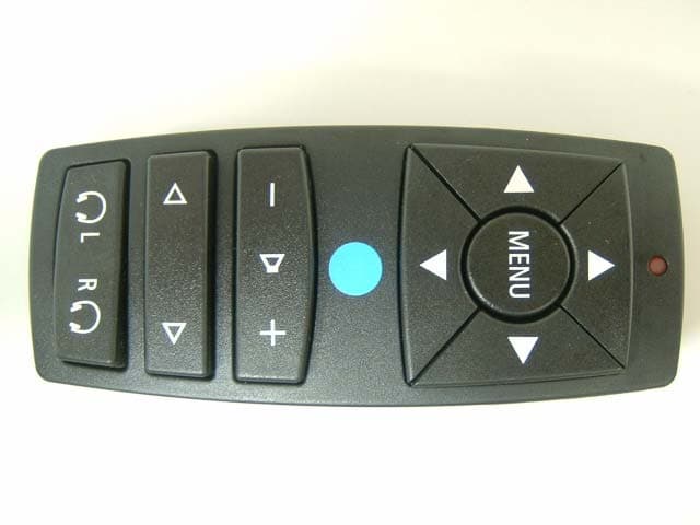
NHVWZU11
Jul 08, 2003Remote Control for the Vehicle
Equipment Class
DSC - Part 15 Security/Remote Control Transmitter
NHVWBU613
Jun 19, 2003Passive Entry System
Equipment Class
DSR - Part 15 Remote Control/Security Device Transceiver
NHVWBU614
Jun 19, 2003Passive Entry System
Equipment Class
DSR - Part 15 Remote Control/Security Device Transceiver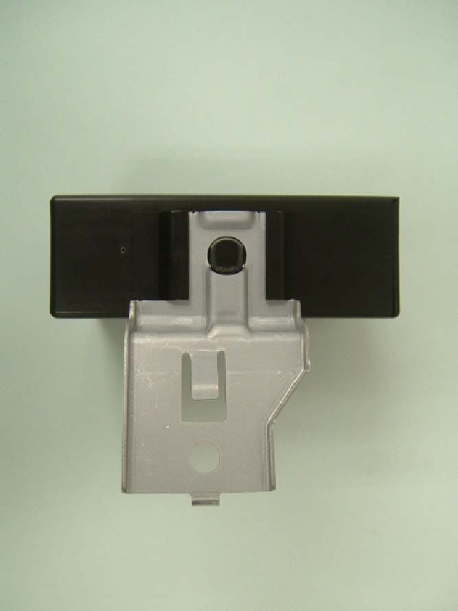
NHVWDU613
Jun 11, 2003Passive Entry System
Equipment Class
DCD - Part 15 Low Power Transmitter Below 1705 kHz
NHVWD1U711
Apr 01, 2003Keyless Entry System Receiver
Equipment Class
CYY - Communications Receiver used w/Pt 15 Transmitter