NI3-AT53V216Atheros 11a/g Mini-PCI Adapter
Senao International Co Ltd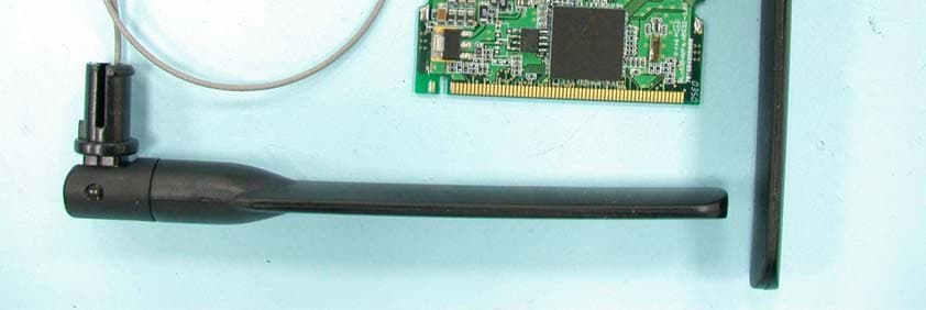
Click to zoom
Application Details
- Equipment Class
- NII - Unlicensed National Information Infrastructure TX
- Date of Grant
- May 18, 2004
- Application Purpose
- Original Equipment
- Date of Application
- May 18, 2004
- Equipment Note
- Atheros 11a/g Mini-PCI Adapter
- Frequency Range
- 5725.00000000 - 5850.00000000
- Company
- Senao International Co Ltd
- Country
- Taiwan
Documents & Files
Document Text
Text extracted from the exhibit documents filed with the FCC. Open a document above to read the original.
Users Manual
0 SENAO High-Speed Wireless Mini PCI Adapter OEM installation Manual Version: 1.0 1 Chapter 1 Introduction 1.1 Feature l Fully interoperable with IEEE 802.11a/g compliant products. l High-Speed data transfer rate up to 108Mbps. l 64-bit and 128-bit WEP Encryption. l MAC Address filtering. l Web-Based Network Manager/Telnet for Configuring and Managing Your access points. l SNMP MIB I and MIB II supported. l Capable of acting as a DHCP Server. l Remote Management supported. l Firmware Upgrade via WEB/TFTP l IEEE802.1x/RADIUS Client (EAP-MD5/TLS/TTLS) Support 1.2 Package Contents l One Access Point (with Mini PCI Adapter) l One CD-ROM with User Guide included l One Power Adapter l One CAT 5 UTP Cable l One Fast Start Guide and One Registration Card Chapter 2 Hardware Configuration 2.1 Hardware Configuration 1. RJ-45 Ethernet connector Provides 10/100 Mbps connectivity to a wired Ethernet LAN. 2. Reset Button By pressing this button for over 3 seconds, the AP will be reset with factory default configuration. 3. Power Supply connector It is for connecting to the power adapter. 2.2 Hardware Installation 1. Configure your notebook or PC with Wireless LAN card. 2. For Wired LAN, connect your PCs’ Ethernet port to any AP’s LAN port by an Ethernet cable. 3. For WLAN, locate the AP to a proper position. 4. Plug the power cord into a power outlet. 2 Chapter 3 Configuring your PC 1. Change the TCP/IP setting of your managing computer. Select the TCP/IP line that has been associated to your network card. Click the Properties button. 2. Make sure the IP address of your computer and the AP are in the same subnet. The default IP address of the access point is 192.168.1.1 and the default subnet mask is 255.255.255.0. 3 3. For WLAN, open the WLAN client utility. Click Configuration tab. Type default SSID (default SSID: wireless) in the Network Name field. Choose “Access Point” for Network Type, then click OK button. Note: the default channel is 6.Configuring the Router through Web Browser Chapter 4 Initial Software Installation and Configuration The access point can be configured through your web browser with the Web-Based Utility. Open your web browser and type the default IP address of the AP in the address field (default IP: 192.168.1.1) and press Enter. Make sure the IP address of AP and your computer are in the same subnet. After the connection is established, you will see the User Login page as shown below. Leave the password field blank when the first time you open the Web-Based utility. You can change the password on the “Administrator settings” page. The system will be time out after idling about 1 minute. You have to login again to re-enter the main setting page. You can change the idle time out period on the “Administrator settings” page. On any page, you can click HELP to obtain more descriptions and explanations. To clear any values you’ve entered on any page, click CANCEL and re-enter information. 4 There are three tabs on the upper right-corner of each page. To go back to the main setting page, press HOME tab. To log out of the web management, press EXIT tab. To complete any change you have made, press RESET tab after clicking APPLY button. 5 Chapter 5 Configuring the Access Point through web browser 5.1.1 Administrator Settings Set a password to restrict management access to the access point. If you want to manage the access point from a remote location (outside of the local network), you must also specify the IP address of the remote PC. Password Settings: To change your password, enter your current password in the “Current Password” box. Enter new password in the “Password” box. Enter it again in the “Re-type password” box to confirm it. Click APPLY to complete your change. The “idle Time Out” is the amount of time of inactivity before the access point will automatically close the Administrator session. Set this to zero to disable it. Remote Management: By default, management access is only available to users on your local network. However, you can also manage the access point from a remote host. Just check the Enable check box and enter the IP address of an administrator to this screen. 6 5.1.2 Firmware Upgrade The firmware information is displayed on this page. You can find firmware version and firmware date here. There are two ways to upgrade the firmware: “Using TFTP” and “Using WEB”. Click “NEXT” button to choose the one you want. l Using TFTP On the managed computer, run the TFTP Server utility. And specify the folder in which the firmware file resides. After running the TFTP server, enter the TFTP server IP and the filename on the following page. Click on APPLY to complete your change. 7 l Using WEB Type the correct firmware file path and file name on the File field. You can click Browse to select the file location. Click on APPLY to complete your change. 5.1.3 Configuration Tools This tool can backup or restore the AP’s configuration. It can also restore the original factory default settings. l Restore Factory default configuration: (1) Chick the “Restore Factory Default Configuration” button and then click NEXT. 8 (2) Click Restore button to force the access point to perform reset and restore the original factory settings. l Backup Setting/Restore Settings: (1) Check the “Backup Settings/Restore Settings” radio button and click NEXT. (2) To save the access point's current configuration to a file named "config.bin" on your PC, click Backup Settings button. (3) To restore configuration, you can use the "Restore Settings" tool to restore the saved configuration of the access point. (4) Enter the path and file name then click Restore Settings button. You can also click Browse to locate and select the previously saved backup file. 9 5.1.4 Status The Status window displays current information and settings for your AP. It has five main parts – LAN, Wireless 11a, Wireless 11g, System Information. 10 For LAN, it displays AP’s IP address, MAC address, and Subnet Mask. It also displays the…
Text truncated - open the document above for the full version.
Cover Letter(s)
American Telecommunications Certification Body Inc. 6731 Whittier Ave, McLean, VA 22101 April 28, 2004 RE: FCC ID: N13-AT53V216_ATCB001302 Attention: Ellis Wu I have a few comments on this Application. 1. Please note that the manual states the device operates in the 5.45 to 5.725 GHz band. Please note that at this time as this requires DFS and TPC functionality only the FCC can certify a device in this band for the US. Please verify if this band is or is not operational in this device. 2. Please note that in line with item 1, testing of the frequency band 5.45 to 5.725GHz was not done. As such, please provide evidence that this band cannot be selected by the end user and please explain how this band is eliminated from selection by the OEM integrator for this device in the US. 3. Please note that the recommended end user rf exposure statement shown on the last page of the manual must also include notice of the required 20cm separation distance. Please re- phrase your recommended statement to include this separation distance statement as well as the no collocation warning statement. 4. Please note that the last statement in the manual can be considered confusing to the operator of the equipment. It appears to be saying that in the 5.15 to 5.25 GHz range that the device cannot be operated indoors. This is opposite of the requirements. The last part of the sentence appears to be a ‘left over’ from the non-modification statement (“could void the user’s authority to operate the equipment”). This frequency range MUST be operated indoors. Please re-phrase your last statement to clearly define and state the requirement for indoor use in this range (i.e. remove the last part of the sentence as shown above). 5. Please note that the operational description states that the 15.247 and the 15.407 devices can transmit simultaneously. However, the schematics would indicate that either the 15.247 or the 15.407 frequency band is selected. Please explain and please provide an accurate operational description of how this device operates simultaneously or otherwise. If simultaneous operation is possible, please describe how this is done (i.e. is the second antenna used for the other band – and if the same antenna or a second antenna is used by the other band?) 6. Please note that if a second antenna is used, this makes the two antennae collocated. The MPE as well as the EMC report then need to address this configuration.) Please explain. 7. Please note that the device has two antenna connection points, yet the test setup photos only show one antenna connected to the EUT. Please explain why the other antenna was not connected. Dennis Ward mailto:[email protected] The items indicated above must be submitted before processing can continue on the above referenced application. Failure to provide the requested information may result in application termination. Correspondence should be considered part of the permanent submission and may be viewed from the Internet after a Grant of Equipment Authorization is issued. Please do not respond to this correspondence using the email reply button. In order for your response to be processed expeditiously, you must submit your documents through the AmericanTCB.com website. Also, please note that partial responses increase processing time and should not be submitted. Any questions about the content of this correspondence should be directed to the sender.
ID Label/Location Info
Label Location
Internal Photos
Page 1 Page 2 Page 3
Operational Description
FCC ID: N13-AT53V216 Report No.RF921215R02A Technical Description The transmitter of the EUT is powered from host equipment. The antenna is Dipole antenna with UFL antenna connector. Under normal use condition, the user has to keep at least 20cm separation distance between radiator and the body of the user. For more detailed instruction, please take a look at the user’s manual. FCC 15.407(c) states: The device shall automatically discontinue transmission in case of either absence of information to transmit or operational failure. These provisions are not intended to preclude the transmission of control or signaling information or the use of repetitive codes used by certain digital technologies to complete frame or burst intervals. Applicants shall include in their application for equipment authorization a description of hoe this requirement is met” Data transmission is always initiated by software, which is then pass down through the MAC, through the digital and analog baseband, and finally to the RF chip. Several special packets (ACKs, CTS, PSPoll, etc...) are initiated by the MAC. There are the only ways the digital baseband portion will turn on the RF transmitter, which it then turns off at the end of the packet. Therefore, the transmitter will be on only while one of the aforementioned packets are being transmitted.
RF Exposure Info
FCC ID: N13-AT53V216 Report No: RF921215R02A 1 RF EXPOSURE REPORT REPORT NO.: RF921215R02A MODEL NO.: NL-5354MP Plus Aries2 ACCORDING: FCC Guidelines for Human Exposure IEEE C95.1 APPLICANT: SENAO INTERNATIONAL CO., LTD. ADDRESS: 2F, No. 531 CHUNG CHENG RD., HSIN-TIEN, TAIPEI, TAIWAN, R. O. C. ISSUED BY: Advance Data Technology Corporation LAB LOCATION: 47 14th Lin, Chiapau Tsun, Linko, Taipei, Taiwan, R.O.C. FCC ID: N13-AT53V216 Report No: RF921215R02A 2 RF Exposure Measurement (Mobile Device) 1. Introduction In this document, we try to prove the safety of radiation harmfulness to the human body for our product. The limit for Maximum Permissible Exposure (MPE) specified in FCC 1.1310 is followed. The Gain of the antenna used in this product is measured in a Fully Anechoic Chamber (FAC) calibrated for antenna measurement in ADT, and also the maximum total power input to the antenna is measured. Through the Friis transmission formula and the maximum gain of the antenna, we can calculate the distance, away from the product, where the limit of MPE is reached. Although the Friis transmission formula is a far field assumption, the calculated result of that is an over-prediction for near field power density. We will take that as the worst case to specify the safety range. 2. RF Exposure Limit According to FCC 1.1310: The criteria listed in the following table shall be used to evaluate the environmental impact of human exposure to radio-frequency (RF) radiation as specified in 1.1307(b) LIMITS FOR MAXIMUM PERMISSIBLE EXPOSURE (MPE) Frequency Range (MHz) Electric Field Strength (V/m) Magnetic Field Strength (A/m) Power Density (mW/cm 2 ) Average Time (minutes) (A)Limits For Occupational / Control Exposures 300-1500......F/3006 1500-100,000......56 (B)Limits For General Population / Uncontrolled Exposure 300-1500......F/15006 1500-100,000......1.030 F = Frequency in MHz FCC ID: N13-AT53V216 Report No: RF921215R02A 3 3. Friis Formula Friis transmission formula : Pd = (Pout*G) / (4*pi*r 2 ) where Pd = power density in mW/cm 2 Pout = output power to antenna in mW G = gain of antenna in linear scale Pi = 3.1416 R = distance between observation point and center of the radiator in cm If we know the maximum Gain of the antenna and the total power input to the antenna, through the calculation, we will know the MPE value at distance r. Ref. : David K. Cheng, Field and Wave Electromagnetics, Second Edition, Page 640, Eq. (11-133). 4 EUT Operating condition The software provided by Manufacturer enabled the EUT to transmit and receive data at lowest, middle and highest channel individually. 5. Classification This modular is specified to be installed in access point or router which is connected with host through wire. So it is easy to be re-located in the place where at least 20cm far away from the body of the user. Warning statement to the user for keeping at least 20cm or more separation distance with the antenna should be included in users manual. So, this device is classified as Mobile Device. FCC ID: N13-AT53V216 Report No: RF921215R02A 4 6 Test Results 6.1 Antenna Gain The maximum Gain measured in Fully Anechoic Chamber is 2dBi or 1.58 (numeric). 6.2 Output Power Into Antenna & RF Exposure value at distance 20cm: For 802.11b: Channel Channel Frequency (MHz) Output Power to Antenna (mW) Power Density (mW/cm 2 ) Limit of Power Density (mW/cm 2 ) 1241252.4810.0171.0 6243757.5440.0181.0 11246254.9540.0171.0 For 802.11g (Normal mode): Channel Channel Frequency (MHz) Output Power to Antenna (mW) Power Density (mW/cm 2 ) Limit of Power Density (mW/cm 2 ) 12412100.0000.0321.0 6243783.1760.0261.0 11246285.1140.0271.0 For 802.11g (Turbo mode): Channel Channel Frequency (MHz) Output Power to Antenna (mW) Power Density (mW/cm 2 ) Limit of Power Density (mW/cm 2 ) 6243763.0960.0201.0 FCC ID: N13-AT53V216 Report No: RF921215R02A 5 For 802.11a Frequency 5.15~5.35GHz (Normal mode): Channel Channel Frequency (MHz) Output Power to Antenna (mW) Power Density (mW/cm 2 ) Limit of Power Density (mW/cm 2 ) 1518017.4580.0061.0 4524017.5390.0061.0 5526017.3780.0051.0 8532015.2050.0051.0 For 802.11a Frequency 5.15~5.35GHz (Turbo mode): Channel Channel Frequency (MHz) Output Power to Antenna (mW) Power Density (mW/cm 2 ) Limit of Power Density (mW/cm 2 ) 1521015.8490.0051.0 2525014.7570.0051.0 3529014.4210.0051.0 For 802.11a Frequency 5.725~5.850GHz (Normal mode): Channel Channel Frequency (MHz) Output Power to Antenna (mW) Power Density (mW/cm 2 ) Limit of Power Density (mW/cm 2 ) 9574510.0000.0031.0 11578510.7150.0031.0 13582510.2330.0031.0 For 802.11a Frequency 5.725~5.850GHz (Turbo mode): Channel Channel Frequency (MHz) Output Power to Antenna (mW) Power Density (mW/cm 2 ) Limit of Power Density (mW/cm 2 ) 457607.9430.0031.0 558006.9180.0021.0
Test Report
FCC ID: N13-AT53V216 Report No.: RF921215R02AIssued: April 16, 2004 Reference No.: RF921215R02 1 FCC TEST REPORT REPORT NO.: RF921215R02A MODEL NO.: NL-5354MP Plus Aries2 RECEIVED: November 12, 2003 TESTED: November 12, 2003 ~ April 16, 2004 APPLICANT: SENAO INTERNATIONAL CO., LTD. ADDRESS: 2F, No. 531 CHUNG CHENG RD., HSIN-TIEN, TAIPEI, TAIWAN, R. O. C. ISSUED BY: Advance Data Technology Corporation LAB LOCATION: 47 14 th Lin, Chiapau Tsun, Linko, Taipei, Taiwan, R.O.C. This test report consists of 206 pages in total. It may be duplicated completely for legal use with the approval of the applicant. It should not be reproduced except in full, without the written approval of our laboratory. The client should not use it to claim product endorsement by CNLA or any government agencies. The test results in the report only apply to the tested sample. 0528 ILAC MRA FCC ID: N13-AT53V216 Report No.: RF921215R02AIssued: April 16, 2004 Reference No.: RF921215R02 2 Table of Contents 1CERTIFICATION ......................................................................................................7 2SUMMARY OF TEST RESULTS ..............................................................................8 3GENERAL INFORMATION.....................................................................................10 3.1GENERAL DESCRIPTION OF EUT.......................................................................10 3.2DESCRIPTION OF TEST MODES......................................................................... 11 3.3GENERAL DESCRIPTION OF APPLIED STANDARDS ........................................12 3.4DESCRIPTION OF SUPPORT UNITS ...................................................................13 3.5CONFIGURATION OF SYSTEM UNDER TEST ....................................................13 4TEST TYPES AND RESULTS (FOR PART 802.11b & 802.11g) ............................14 4.1CONDUCTED EMISSION MEASUREMENT .........................................................14 4.1.1 LIMITS OF CONDUCTED EMISSION MEASUREMENT.......................................14 4.1.2 TEST INSTRUMENTS............................................................................................14 4.1.3 TEST PROCEDURES ............................................................................................15 4.1.4 DEVIATION FROM TEST STANDARD ..................................................................15 4.1.5 TEST SETUP .........................................................................................................16 4.1.6 EUT OPERATING CONDITIONS ...........................................................................16 4.1.7 TEST RESULTS .....................................................................................................17 4.2RADIATED EMISSION MEASUREMENT ..............................................................23 4.2.1 LIMITS OF RADIATED EMISSION MEASUREMENT............................................23 4.2.2 TEST INSTRUMENTS............................................................................................24 4.2.3 TEST PROCEDURES ............................................................................................25 4.2.4 DEVIATION FROM TEST STANDARD ..................................................................25 4.2.5 TEST SETUP .........................................................................................................26 4.2.6 EUT OPERATING CONDITIONS ...........................................................................26 4.2.7 TEST RESULTS .....................................................................................................27 4.36dB BANDWIDTH MEASUREMENT .....................................................................36 4.3.1 LIMITS OF 6dB BANDWIDTH MEASUREMENT ...................................................36 4.3.2 TEST INSTRUMENTS............................................................................................36 4.3.3 TEST PROCEDURE...............................................................................................37 4.3.4 DEVIATION FROM TEST STANDARD ..................................................................37 4.3.5 TEST SETUP .........................................................................................................37 4.3.6 EUT OPERATING CONDITIONS ...........................................................................37 4.3.7 TEST RESULTS .....................................................................................................38 FCC ID: N13-AT53V216 Report No.: RF921215R02AIssued: April 16, 2004 Reference No.: RF921215R02 3 4.4MAXIMUM PEAK OUTPUT POWER .....................................................................47 4.4.1 LIMITS OF MAXIMUM PEAK OUTPUT POWER MEASUREMENT......................47 4.4.2 INSTRUMENTS......................................................................................................47 4.4.3 TEST PROCEDURES ............................................................................................48 4.4.4 DEVIATION FROM TEST STANDARD ..................................................................48 4.4.5 TEST SETUP .........................................................................................................48 4.4.6 EUT OPERATING CONDITIONS ...........................................................................48 4.4.7 TEST RESULTS .....................................................................................................49 4.5POWER SPECTRAL DENSITY MEASUREMENT.................................................50 4.5.1 LIMITS OF POWER SPECTRAL DENSITY MEASUREMENT ..............................50 4.5.2 TEST INSTRUMENTS............................................................................................50 4.5.3 TEST PROCEDURE...............................................................................................50 4.5.4 DEVIATION FROM TEST STANDARD ..................................…
Text truncated - open the document above for the full version.
Test Report
FCC ID: N13-AT53V216 Report No.: RF921215R02AIssued: April 16, 2004 Reference No.: RF921215R02 71 OFDM (Turbo mode) FCC ID: N13-AT53V216 Report No.: RF921215R02AIssued: April 16, 2004 Reference No.: RF921215R02 72 FCC ID: N13-AT53V216 Report No.: RF921215R02AIssued: April 16, 2004 Reference No.: RF921215R02 73 FCC ID: N13-AT53V216 Report No.: RF921215R02AIssued: April 16, 2004 Reference No.: RF921215R02 74 FCC ID: N13-AT53V216 Report No.: RF921215R02AIssued: April 16, 2004 Reference No.: RF921215R02 75 4.7 ANTENNA REQUIREMENT 4.7.1 STANDARD APPLICABLE For intentional device, according to FCC 47 CFR Section 15.203, an intentional radiator shall be designed to ensure that no antenna other than that furnished by the responsible party shall be used with the device. And according to FCC Section 15.247 (b), if transmitting antennas of directional gain greater than 6dBi are used, the power shall be reduced by the amount in dB that the directional gain of the antenna exceeds 6dBi. 4.7.2 ANTENNA CONNECTED CONSTRUCTION The antenna used in this product is Dipole antenna with UFL antenna connector. The maximum Gain of the antenna is 2dBi. FCC ID: N13-AT53V216 Report No.: RF921215R02AIssued: April 16, 2004 Reference No.: RF921215R02 76 5 TEST TYPES AND RESULTS (FOR PART 802.11a) 5.1 CONDUCTED EMISSION MEASUREMENT 5.1.1 LIMITS OF CONDUCTED EMISSION MEASUREMENT FREQUENCY OF EMISSION (MHz)CONDUCTED LIMIT (dBμV) Quasi-peakAverage 0.15-0.5 0.5-5 5-30 66 to 56 56 60 56 to 46 46 50 NOTE:1. The lower limit shall apply at the transition frequencies. 2. The limit decreases in line with the logarithm of the frequency in the range of 0.15 to 0.50 MHz. 3. All emanations from a class A/B digital device or system, including any network of conductors and apparatus connected thereto, shall not exceed the level of field strengths specified above. 5.1.2 TEST INSTRUMENTS DESCRIPTION & MANUFACTURERMODEL NO.SERIAL NO. CALIBRATED UNTIL ROHDE & SCHWARZ Test Receiver ESHS 30828765/002July 15, 2004 ROHDE & SCHWARZ Artificial Mains Network (for EUT) ESH3-Z5835239/001Apr. 28, 2004 ROHDE & SCHWARZ Artificial Mains Network (for peripherals) ESH3-Z5835239/002Apr. 28, 2004 ROHDE & SCHWARZ 4-wire ISN ENY41935154/007Apr. 30, 2004 ROHDE & SCHWARZ 2-wire ISN ENY22833823/026Apr. 30, 2004 SoftwareCond-V2M3NANA RF cable (JYEBAO)5D-FBCable-C09.01May 23, 2004 SUHNER Terminator (For ROHDE & SCHWARZ LISN) 65BNC-5001E1-010789Jun. 04, 2004 NOTE: 1. The calibration interval of the above test instruments is 12 months and the calibrations are traceable to NML/ROC and NIST/USA. 2. “*”: These equipment are used for conducted telecom port test only (if tested). 3. The test was performed in ADT Shielded Room No. 9. 4. The VCCI Site Registration No. is C-1312. FCC ID: N13-AT53V216 Report No.: RF921215R02AIssued: April 16, 2004 Reference No.: RF921215R02 77 5.1.3 TEST PROCEDURES a. The EUT was placed 0.4 meters from the conducting wall of the shielded room with EUT being connected to the power mains through a line impedance stabilization network (LISN). Other support units were connected to the power mains through another LISN. The two LISNs provide 50 ohm/ 50uH of coupling impedance for the measuring instrument. b. Both lines of the power mains connected to the EUT were checked for maximum conducted interference. c. The frequency range from 150kHz to 30MHz was searched. Emission levels under (limit –20dB) was not recorded. 5.1.4 DEVIATION FROM TEST STANDARD No deviation FCC ID: N13-AT53V216 Report No.: RF921215R02AIssued: April 16, 2004 Reference No.: RF921215R02 78 4.7.3 TEST SETUP For the actual test configuration, please refer to the related item – Photographs of the Test Configuration. 5.1.5 EUT OPERATING CONDITIONS Same as 4.1.6. FCC ID: N13-AT53V216 Report No.: RF921215R02AIssued: April 16, 2004 Reference No.: RF921215R02 79 5.1.6 TEST RESULTS EUT Atheros 11a/g Mini-PCI Adapter MODEL NL-5354MP Plus Aries2 INPUT POWER (SYSTEM) 120Vac, 60 Hz 6dB BANDWIDTH 9kHz ENVIRONMENTAL CONDITIONS 30deg. C, 85%RH, 991hPa PHASE Line (L) TESTED BY Vincent Lin Freq.Corr. Reading Value Emission Level LimitMargin NoFactor[dB (uV)][dB (uV)][dB (uV)](dB) [MHz](dB)Q.P.AV.Q.P.AV.Q.P.AV.Q.P.AV. 10.1680.1052.47-52.57-65.0655.06-12.49- 20.2250.1144.15-44.26-62.6352.63-18.37- 30.4460.2035.50-35.70-56.9546.95-21.25- 43.2900.2628.82-29.08-56.0046.00-26.92- 519.5221.0822.26-23.34-60.0050.00-36.66- 622.6011.2021.09-22.29-60.0050.00-37.71- REMARKS: 1. Q.P. and AV. are abbreviations of quasi-peak and average individually. 2. "-": The Quasi-peak reading value also meets average limit and measurement with the average detector is unnecessary. 3. The emission levels of other frequencies were very low against the limit. 4. Margin value = Emission level - Limit value 5. Correction factor = Insertion loss + Cable loss 6. Emission Level = Correction Factor + Reading Value. FCC ID: N13-AT53V216 Report No.: RF921215R02AIssued: April 16, 2004 Reference No.: RF921215R02 80 EUT Atheros 11a/g Mini-PCI Adapter MODEL NL-5354MP Plus Aries2 INPUT POWER (SYSTEM) 120Vac, 60 Hz 6dB BANDWIDTH 9kHz ENVIRONMENTAL CONDITIONS 30deg. C, 85%RH, 991hPa PHASE Neutral (N) TESTED BY Vincent Lin Freq.Corr. Reading Value Emission Level LimitMargin NoFactor[dB (uV)][dB (uV)][dB (uV)](dB) [MHz](dB)Q.P.AV.Q.P.AV.Q.P.AV.Q.P.AV. 10.1680.1051.32-51.42-65.0655.06-13.64- 20.2250.1142.29-42.40-62.6352.63-20.23- 30.9480.2025.31-25.51-56.0046.00-30.49- 43.2890.2031.87-32.07-56.0046.00-23.93- 516.5020.8323.70-24.53-60.0050.00-35.47- 619.3550.8924.86-25.75-60.0050.00-34.25- REMARKS: 1. Q.P. and AV. are abbreviations of quasi-peak and average individually. 2. "-": The Quasi-peak reading value also meets average limit and measurement with the average detector is unnecessary. 3. The emission levels of other frequencies were very low against the limit. 4. Margin value = Emission level - Limit value 5. Correction factor = Insertion loss + Cable loss 6. Emission Level = Correction Factor + Reading Value. FCC ID: N13-AT53V216 Report…
Text truncated - open the document above for the full version.
Test Report
FCC ID: N13-AT53V216 Report No.: RF921215R02AIssued: April 16, 2004 Reference No.: RF921215R02 121 CHANNEL 1 FCC ID: N13-AT53V216 Report No.: RF921215R02AIssued: April 16, 2004 Reference No.: RF921215R02 122 CHANNEL 4 FCC ID: N13-AT53V216 Report No.: RF921215R02AIssued: April 16, 2004 Reference No.: RF921215R02 123 CHANNEL 5 FCC ID: N13-AT53V216 Report No.: RF921215R02AIssued: April 16, 2004 Reference No.: RF921215R02 124 CHANNEL 8 FCC ID: N13-AT53V216 Report No.: RF921215R02AIssued: April 16, 2004 Reference No.: RF921215R02 125 EUT Atheros 11a/g Mini-PCI Adapter MODEL NL-5354MP Plus Aries2 MODE Turbo INPUT POWER (SYSTEM) 120Vac, 60 Hz ENVIRONMENTAL CONDITIONS 25deg. C, 60%RH, 991hPa TESTED BY Gary Chang CHANNEL CHANNEL FREQUENCY (MHz) PEAK POWER EXCURSION (dB) PEAK to AVERAGE EXCURSION LIMIT (dB) PASS/FAIL 152107.8113PASS 252507.8113PASS 352907.5113PASS FCC ID: N13-AT53V216 Report No.: RF921215R02AIssued: April 16, 2004 Reference No.: RF921215R02 126 CHANNEL 1 FCC ID: N13-AT53V216 Report No.: RF921215R02AIssued: April 16, 2004 Reference No.: RF921215R02 127 CHANNEL 2 FCC ID: N13-AT53V216 Report No.: RF921215R02AIssued: April 16, 2004 Reference No.: RF921215R02 128 CHANNEL 3 FCC ID: N13-AT53V216 Report No.: RF921215R02AIssued: April 16, 2004 Reference No.: RF921215R02 129 5.5 PEAK POWER SPECTRAL DENSITY MEASUREMENT 5.5.1 LIMITS OF PEAK POWER SPECTRAL DENSITY MEASUREMENT Frequency BandLimit 5.15 – 5.25GHz4dBm 5.25 – 5.35GHz11dBm 5.725 – 5.825GHz17dBm 5.5.2 TEST INSTRUMENTS Description & ManufacturerModel No.Serial No.Calibrated Until SPECTRUM ANALYZERFSEK30100049Aug. 12, 2004 NOTE: The calibration interval of the above test instruments is 12 months and the calibrations are traceable to NML/ROC and NIST/USA. FCC ID: N13-AT53V216 Report No.: RF921215R02AIssued: April 16, 2004 Reference No.: RF921215R02 130 5.5.3 TEST PROCEDURES 1. The transmitter output was connected to the spectrum analyzer. 2. Set RBW=1MHz, VBW=3MHz. The PPSD is the highest level found across the emission in any 1MHz band. 5.5.4 DEVIATION FROM TEST STANDARD No deviation 5.5.5 TEST SETUP 5.5.6 EUT OPERATING CONDITIONS Same as 5.3.6 EUT SPECTRUM ANALYZER FCC ID: N13-AT53V216 Report No.: RF921215R02AIssued: April 16, 2004 Reference No.: RF921215R02 131 5.5.7 TEST RESULTS EUT Atheros 11a/g Mini-PCI Adapter MODEL NL-5354MP Plus Aries2 MODE Normal INPUT POWER (SYSTEM) 120Vac, 60 Hz ENVIRONMENTAL CON…
Text truncated - open the document above for the full version.
Contact Information
Applicant
Havin Lu(Director)
Technical Contact
Advance Data Technology CorporationEllis Wu
[email protected]886-318-3232
No. 19, Hwa Ya 2nd rd., Kueishan · Taoyuan · Taiwan
Test Firm
Advance Data Technology CorporationStephen Chen
Technical Specifications
| # | Rule Parts | Frequency Range | Power Output |
|---|---|---|---|
| 3 | 15E | 5.72 GHz - 5.85 GHz | 11.00 mW |
Other Applications from Senao International Co Ltd

NI3-SR32106001
Mar 28, 2007Wireless LAN IEEE 802.11b/g Router
Equipment Class
DTS - Digital Transmission System
NI3-MP36006001
Feb 05, 2007IEEE 802.11b/g Wireless Mini-PCI Adaptor
Equipment Class
DTS - Digital Transmission System
NI3-OC86706001
Feb 05, 2007IEEE802.11a/g/b NWH3054A WLAN mini-PCI
Equipment Class
DTS - Digital Transmission System
NI3-OC32106001
May 25, 2006Outdoor 802.11 b/g AP/CB
Equipment Class
DTS - Digital Transmission System
NI3-CB32106001
May 14, 200611g Wireless Multi-Client Bridge/ Router/AP/WDS
Equipment Class
DTS - Digital Transmission System