NI3-EP-2362.4GHz Frequency Hopping Cordless Telephone
Senao International Co Ltd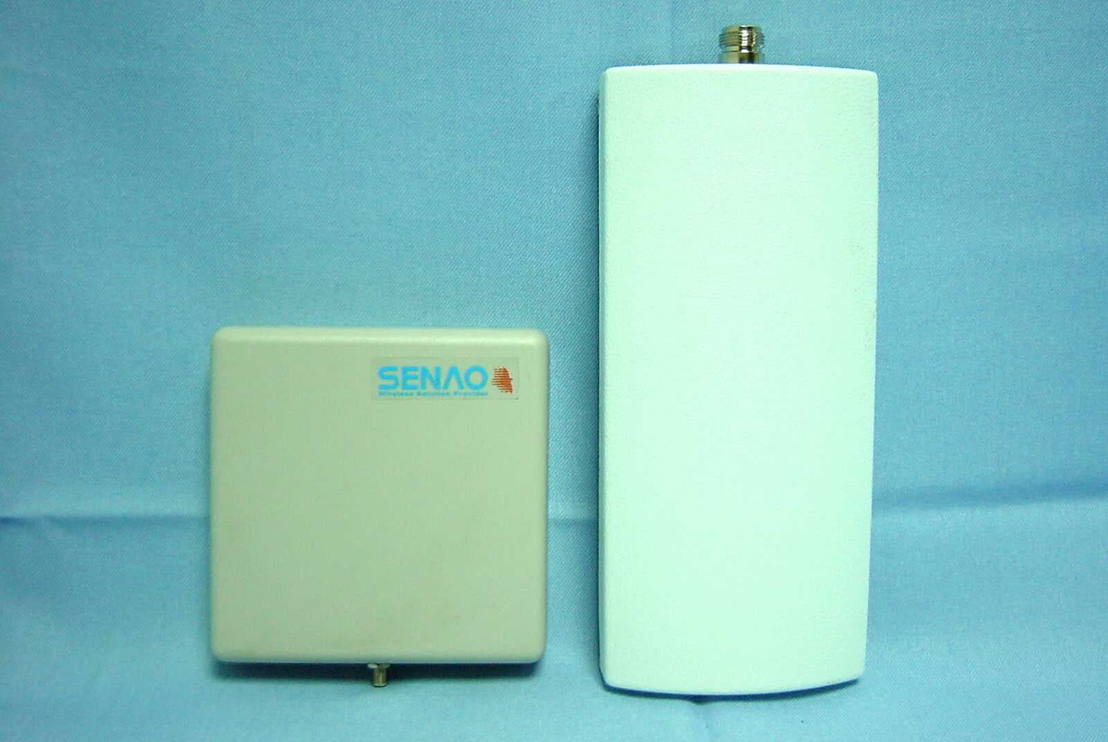
Click to zoom
Application Details
- Equipment Class
- DSS - Part 15 Spread Spectrum Transmitter
- Date of Grant
- Dec 10, 2002
- Application Purpose
- Original Equipment
- Date of Application
- Dec 03, 2002
- Equipment Note
- 2.4GHz Frequency Hopping Cordless Telephone
- Frequency Range
- 2401.00000000 - 2480.00000000
- Company
- Senao International Co Ltd
- Country
- Taiwan
Documents & Files
Document Text
Text extracted from the exhibit documents filed with the FCC. Open a document above to read the original.
Users Manual
Draft version EP-236-1.1UM Confidential – Do Not Reproduce or Forward User’s Manual EP-236 2-line Communication System EnGenius Customer Service United States: 1-888-735-7888 Canada: 1-888-397-2788 Draft version EP-236-1.1UM Confidential – Do Not Reproduce or Forward 2 Table of Contents Safety Instructions .................................................................................................... 4 General Safety Instructions ...................................................................... 4 Product Safety Instructions ....................................................................... 5 Battery Safety Instructions ........................................................................ 6 Regulatory Information ............................................................................................. 8 Congratulations......................................................................................................... 9 Equipment Checklist ............................................................................................... 11 Handset Features ................................................................................................... 12 Basic Handset Features .......................................................................... 12 Additional Handset Features .................................................................. 13 Base Features ........................................................................................................ 18 Basic Base Station Features .................................................................. 18 Additional Base Station Features ......................................................... 18 Administrator Features ............................................................................. 19 Getting Started........................................................................................................ 21 Base Station Installation .......................................................................... 21 Handset and Charger Installation ......................................................... 22 Basic Operations .................................................................................................... 23 Making a Telephone Call ......................................................................... 23 Making an Intercom Call to Base Station .......................................... 23 Making an Intercom Call to another Handset .................................. 23 Redial .............................................................................................................. 24 Receiving a Telephone Call ................................................................... 24 Receiving an Intercom Call ..................................................................... 25 Ending a Call ................................................................................................ 25 Adjusting Receiver (Earpiece) Voice Volume .................................. 25 Placing a Call On Hold ............................................................................. 25 Mute ................................................................................................................ 26 Do Not Disturb (Silent Ring) ................................................................... 26 Key Guard ..................................................................................................... 27 Battery Recharge and Replacement ................................................... 27 Advanced Operations ............................................................................................. 28 Handset Registration ................................................................................ 28 Handset Group Subscription .................................................................. 29 Call Transfer ................................................................................................. 30 3-Way Conferencing ................................................................................. 30 Call Forwarding ........................................................................................... 31 Auto-Attendant (AA) .................................................................................. 32 Call Waiting (integrated w/ system) ..................................................... 33 AA Configuration by Administrator ....................................................... 34 Phonebook Operations ............................................................................ 36 Menu Operations ........................................................................................ 39 Voicemail Operations ................................................................................ 41 Draft version EP-236-1.1UM Confidential – Do Not Reproduce or Forward 3 Technical Specifications ......................................................................................... 43 Federal Communications Commission (FCC) Statement ............................ 44 Federal Communications Commission (FCC) Statement....................................... 44 Draft version EP-236-1.1UM Confidential – Do Not Reproduce or Forward 4 Safety Instructions Caution : Your wireless telephone gives you freedom and flexibility to stay in touch while you move around. However, the safe and responsible use of the phone depends entirely on you. When using your phone equipment, safety instructions should be followed to avoid the risk of fire, electric shock, injury to person, and damage to property. General Safety Instructions 1. When using your wireless phone, ensure your safety and the safety of others: a. Always watch where you are walking and standing. b. Don’t let a phone call distract you from working safely. 2. In an emergency: a. If an emergency occurs, dial the emergency phone number. Remember: if you are in an area where your phone does not have a clear signal fro…
Text truncated - open the document above for the full version.
Cover Letter(s)
From: Eva Kao [[email protected]] Sent: Thursday, October 31, 2002 7:33 PM To: Mike Kuo; Helen Zhao Subject: Re: Senao International Co., Ltd., FCC ID:NI3-EP-236, AN02T2274 Hi Mike, Answer 1: Please find the attached is resive test report part 1. Best Regards, Eva ----- Original Message ----- From: "Eva Kao" <[email protected]> To: "Mike Kuo" <[email protected]>; "Helen Zhao" <[email protected]> Sent: Thursday, October 31, 2002 3:48 PM Subject: Re: Senao International Co., Ltd., FCC ID:NI3-EP-236, AN02T2274 > Hi Mike, > > Answer 1: Please find the attached is antenna spec. > > Answer 2-3: Please find the attached is the resive user manual. About the > question 2, the client indicate there isn't function of this device, so they > cancel it in the user manual. > > Answer 4: Please find the attached is revise FCC ID Label > > Answer 5: I didn't understand why we need to add the 15.241 (c) of FCC rules > on the FCC ID label? > > Answer 6: Please find the attached is internal antenna for your reference. > > > Thanks for your help. > Eva > > > > -----Original Message----- > > From: CERTADM > > Sent: Thursday, October 24, 2002 6:12 PM > > To: '[email protected]' > > Subject: Senao International Co., Ltd., FCC ID:NI3-EP-236, AN02T2274 > > > > > > Notice_content > > ------------- > > Question #1: Please provide a separate cover letter to list all antennas > > that are included in the 15.247 test report. In this cover letter, please > > list the antenna type, antenna gain, type of antenna connector, the length > > of supplied cable, cable lost and installation procedures to the end user. > > > > Question #2: In the user manual, it lists optional accessories ( remote > > repeater ). Such optional accessories did not mention in the test report > or > > tested. Please explain. > > > > Question #3: Page 44 of user manual, FCC RF exposure warning statement is > > written in such way will confuse the user. Please provide proper RF > > exposure warning statement and make sure to inform the user how to use the > > handset and base station to compliance RF exposure requirements. In > > addition, inform the user the separation distance that end user should > > maintain for various type of antennas. > > > > Question #4: The application is intended for base and handset under single > > FCC ID number. The proposed FCC ID label format only indicates the label > > will be located at base station. FCC ID label should be also placed on > the > > handset as well. Please provide revised FCC ID label format and location. > > > > Question #5: The statement required under Section 15.241 ( c ) of FCC > rules > > shall be placed on the FCC ID label. > > > > Question #6: The specification sheet for internal antenna can not be read. > > Please provide a clear copy of file. > > > > 15.247 Portion of Test Report > > > > Question #7: Section 2.2 and Section 4. of test report, please provide > > detail description on the " Engineering mode " or " Software " that were > > used during the tests. What is the method has been employed to change the > > output power Vs channel ? > > > > Question #8 Section 5.2 EUT Setup: PC and External I/O cable are mentioned > > but such devices can not be located via Setup photos. Please explain. > > > > Question #9: Section 6.1 of test report, this device is frequency hopping > > spread spectrum but direct sequence technical requirement is mentioned. > > Please make necessary correction. > > > > Question #10: Section 6.1 of test report, peak output power table: the > cable > > lost did not use to correct the power reading for base station with > Internal > > and External antenna port during peak power measurement, but cable lost > did > > consider during average power measurement. Please explain the > differences. > > > > Question #11: Page 94 of data : The test condition for this data is when > the > > base is transmitting at Channel 1 ( 2401MHz) with receiving antenna at > > vertical. As indicated from the spectrum plots, the fundamental emission > > can be not be seen on the spectrum plots. It appears the spurious > emissions > > are higher than the fundamental emissions. Please explain. > > Note : please go over the all radiated emission spectrum plots, most of > > spectrum plots are with same questions. > > > > Question #12: Radiated spurious emission test data for handset. It > > indicates QP at the end of data. What is QP in relate to peak and average > > reading ? > > > > Question #13: Please tune the fundamental frequency for base station to > low > > and high channel and tested with highest gain antenna ( 12dBi gain ) for > > fundamental field strength, and report the highest radiated field strength > > at frequency 2390MHz ( for low channel ) and 2483.5MHz ( for high > channel). > > > > SAR portion : > > > > Question #14: The EUT description described in the SAR report is a direct > > sequence spread spectrum cordless phone. However, all 15.247 tests were > > performed as frequency hopping device. Please explain. > > > > Question #15: Please provide update measurement uncertainty budget per > > P1528. > > > > Question #16: Section 5.4 of SAR report. This device was measured in > > accordance with OET 65 Supplement C. Please explain the nature of > deviation > > as described in the report. > > > > Best Regards > > > > Mike Kuo / TCB Certifier > > The items indicated above must be submitted before processing can continue > > on the above referenced application. Failure to > > provide the requested information within 60 days of the original e-mail > date > > may result in application dismissal and forfeiture of the filing fee. > Also, > > please note that partial responses increase processing time and should not > > be submitted. Any questions about the content of this correspondence > should > > be directed to the e-mail address listed below the name of the sender. > > > > > > >
Cover Letter(s)
From: Eva Kao [[email protected]] Sent: Monday, November 18, 2002 10:55 PM To: Mike Kuo Cc: Scott Wang; ??? ??; Vincent Subject: Re: Senao International Co., Ltd., FCC ID:NI3-EP-236, AN02T2274 Hi Mike, I am not sure whether you received our reply of SENAO as below. Could you please inform me how about the current situation of this project. Thank you very much. Eva > ----- Original Message ----- > From: "Eva Kao" <[email protected]> > To: "Mike Kuo" <[email protected]> > Sent: Friday, November 15, 2002 3:35 PM > Subject: Re: Senao International Co., Ltd., FCC ID:NI3-EP-236, AN02T2274 > > > > Hi Mike, > > > > Please find the attachment are Revised user manual, Antenna install > > procedure and Revised antenna spec. for refer the question as below. > > > > Best Regards, > > Eva > > > > ----- Original Message ----- > > From: "Mike Kuo" <[email protected]> > > To: "'Eva Kao'" <[email protected]>; "Mike Kuo" <[email protected]> > > Cc: "Sunny Shih" <[email protected]>; "CLIENT ADVOCATES" <[email protected]> > > Sent: Thursday, November 07, 2002 2:38 PM > > Subject: RE: Senao International Co., Ltd., FCC ID:NI3-EP-236, AN02T2274 > > > > > > > Hi Eva: > > > > > > The antenna specification sheet provided do not comply with unique > antenna > > > connector requirements. > > > > > > Item #1: O.K. > > > Item #2: N type reversed direction, O.K. but adapter provided which > change > > > from unique connector to standard connector . Does not comply. > > > Item # 3,4, 5 : same reason as item #2 . Do not comply unique connector > > > requirement. > > > > > > Please understand the reason to require unique antenna connector for > > > unlicensed transmitter. Unique connector is to prevent the end user to > > > connect any other antenna to the device. > > > > > > Please discuss with Steven about this case, help the applicant to > > understand > > > the rules. The antenna gain for base station is very high, the EIRP is > > very > > > close to the limits. If the applicant can not provide a clear > instruction > > > on the installation procedures, I will keep on asking the questions. > > > > > > Question #6 : Please provide installation procedures to install the > > external > > > antenna. > > > > > > Question #7 : In the revised user manual, you use the cable length as > the > > > separation distance that the end user should maintain. It is not > > > acceptable. With 1.4 meter cable length, the separation distance may be > > > less than 1.4 meter after the installation. The separation distance > > should > > > be very clear to the end user. Please consider the MPE estimate in > > > determine the separation distance requirement. > > > > > > Best Regards > > > > > > Mike Kuo > > > > > > -----Original Message----- > > > From: Eva Kao [mailto:[email protected]] > > > Sent: Wednesday, November 06, 2002 1:49 AM > > > To: Mike Kuo > > > Cc: Sunny Shih; CLIENT ADVOCATES > > > Subject: Re: Senao International Co., Ltd., FCC ID:NI3-EP-236, AN02T2274 > > > > > > > > > Hi Mike, > > > > > > Answer 1# The Antenna Connectors are considered as unique antenna > > connector, > > > All the connector are revised, please see the Antenna spec list which > was > > > revised and attached again. So the user can not change the antenna and > the > > > cable by themself. > > > > > > Answer 2# Avove description shall be changed as '' switch the output > power > > > to external antenna port''. Due to the RF power was default to transfer > to > > > internal antenna port. > > > By the way, the output power level can't be changed. > > > > > > Answer 3-4# Please find the attached is revise user manual. > > > > > > Answer 5# We had confirmed with client, it was an error, This product > > > doesn't provid this function. we had revised. > > > > > > Answer6# The duty cycle = 0.720/10.14 = 7.1%. Please find the attached > is > > > duty cycle plot. > > > > > > Thanks! > > > Eva > > > > > > > > > > > > ----- Original Message ----- > > > From: "Mike Kuo" <[email protected]> > > > To: "Eva Kao (E-mail)" <[email protected]> > > > Cc: "Sunny Shih" <[email protected]>; "CLIENT ADVOCATES" <[email protected]> > > > Sent: Tuesday, November 05, 2002 3:59 AM > > > Subject: FW: Senao International Co., Ltd., FCC ID:NI3-EP-236, AN02T2274 > > > > > > > > > > > > > > > > > > -----Original Message----- > > > > From: CERTADM > > > > Sent: Monday, November 04, 2002 10:54 AM > > > > To: '[email protected]' > > > > Subject: Senao International Co., Ltd., FCC ID:NI3-EP-236, AN02T2274 > > > > > > > > > > > > Notice_content > > > > ------------- > > > > Second Notices: > > > > > > > > Question #1: The antenna specification submitted for this application > > > listed > > > > several external antennas that will be used for the base station. All > > > > external antenna connectors are either SMA or N type connectors which > > are > > > > considered as standard antenna connectors. Per section 15.203 of FCC > > > rules, > > > > unlicensed transmitter has to equipped with unique antenna connectors. > > In > > > > addition, in accordance with user manual, this device will be marketed > > to > > > > home / office which do not qualify for professional installation as > > well. > > > > Please address this non-compliance issues. > > > > > > > > Question #2: Installation procedures mentioned in the antenna > > > specification: > > > > The installation procedures call out the procedure to set the output > > power > > > > to external antenna. There is no detail instruction given on how to > set > > > the > > > > output power in the user manual or in all other submitted attachments. > > > > Please explain and provide the meaning of set the output power to the > > > > external antenna. > > > > > > > > Question #3: Page 44 of revised user manual. The non co-location > > > > requirement and operating conjunction with other transmitter are the > > > > conditions for the handset as well as to the base station. Please > > revise > > > > the RF exposure statement item #1. > > > > > > > > Question #…
Text truncated - open the document above for the full version.
Cover Letter(s)
From: Eva Kao [[email protected]] Sent: Friday, November 22, 2002 2:38 AM To: Mike Kuo Cc: [email protected]; [email protected]; Scott Wang Subject: Re: Senao International Co., Ltd., FCC ID:NI3-EP-236, AN02T2274 Hi Mike, We used trace A to measure Peak and Trace B to measure Average, the setting at the plot is trace B. You can find two traces in each plot. Upper is Trace A (Peak ), and Lower is trace B( Average). The RBW is setting to 100KHz for frequency above 13GHz Radiate Emission, for the purpose of ascertain this device haven't noise. Best Regards, Eva ----- Original Message ----- From: "Mike Kuo" <[email protected]> To: "Eva Kao (E-mail)" <[email protected]> Cc: <[email protected]>; <[email protected]>; "Scott Wang" <[email protected]> Sent: Friday, November 22, 2002 3:20 AM Subject: FW: Senao International Co., Ltd., FCC ID:NI3-EP-236, AN02T2274 > > > -----Original Message----- > From: CERTADM > Sent: Thursday, November 21, 2002 11:18 AM > To: '[email protected]' > Subject: Senao International Co., Ltd., FCC ID:NI3-EP-236, AN02T2274 > > > Notice_content > ------------- > Notice #3 > > Question #1: Attached please find the revised test report Part 3. As > indicated in the spectrum plots on Page 94-97 radiated bandedge measurement. > You indicated the peak reading is 62.44 dBuv/m @2390MHz/Vertical. This > reading is demonstrated on Page 95 via spectrum plots. On page 95 of > spectrum plots, RBW-1MHz and VBW=10Hz, this is average setting not the peak > setting. So 62.44 dBuV/m should be average reading instead of peak reading. > By considering the correction factor, the corrected average is over the > 15.209 average limits. Same situation for page 96-97. > > Based upon the information present herein, this application will be > dismissed if the explanation to above questions can be justified and > resolved. > > All the test plots submitted in this applications are not clear and most of > spectrum plots do not instrument settings information. It has been a very > difficult task for the reviewer to review this application. If you decided > to provide additional information for this application, all test plots must > be readable and with all instrument settings. > > For you perform radiated spurious emission tests, please follow FCC > measurement guideline, some of radiated emission above 1 GHz you used > RBW=100kHz and VBW=300KHz. This is not acceptable as well. > > Best Regards > > Mike Kuo > The items indicated above must be submitted before processing can continue > on the above referenced application. Failure to provide the requested > information within 60 days of the original e-mail date may result in > application dismissal and forfeiture of the filing fee. Also, please note > that partial responses increase processing time and should not be submitted. > Any questions about the content of this correspondence should be directed to > the e-mail address listed below the name of the sender.
Cover Letter(s)
Antenna Install Procedure Antenna Part No.: IC6500RS-101 1. Mount the Antenna on wall like figure 1 below. 2. Arrange the wire way like figure 1. 3. Connect the RG-316 cabel to BASE of external antenna port. Refer to Fgure 2 Figure 1 Figure 2 Antenna Part No.: PA-010-101/ 1PG-24002 1. Mount the Antenna on wall like figure 3 below. 2. Arrange the wire way like figure 3. 3. Connect the RG-322 cabel to BASE of external antenna port. Refer to Fgure 2 Figure 3 Antenna Part No.: IG-102NR-101/ 1PG-24001 1. Mount the Antenna on ceiling / wall like figure 4 below. 2. Arrange the wire way like figure 4. 3. Connect the RG-322 cabel to BASE of external antenna port. Refer to Fgure 2 Figure 4
External Photos
C&C Laboratory Co. Ltd. REPORT NO: 020033-RF-ID FCC ID: NI3-EP-236 DATE: 09/16/2002 APPENDIX 2 EXTERNAL PHOTOGRPHS OF EUT C&C Laboratory Co. Ltd. REPORT NO: 020033-RF-ID FCC ID: NI3-EP-236 DATE: 09/16/2002 BASE Front View of EUT Back View of EUT C&C Laboratory Co. Ltd. REPORT NO: 020033-RF-ID FCC ID: NI3-EP-236 DATE: 09/16/2002 Left View of EUT Bottom View of EUT C&C Laboratory Co. Ltd. REPORT NO: 020033-RF-ID FCC ID: NI3-EP-236 DATE: 09/16/2002 HANDSET Front View of EUT Back View of EUT C&C Laboratory Co. Ltd. REPORT NO: 020033-RF-ID FCC ID: NI3-EP-236 DATE: 09/16/2002 Right View of EUT Left View of EUT C&C Laboratory Co. Ltd. REPORT NO: 020033-RF-ID FCC ID: NI3-EP-236 DATE: 09/16/2002 ANTENNA C&C Laboratory Co. Ltd. REPORT NO: 020033-RF-ID FCC ID: NI3-EP-236 DATE: 09/16/2002 C&C Laboratory Co. Ltd. REPORT NO: 020033-RF-ID FCC ID: NI3-EP-236 DATE: 09/16/2002 Front View of EUT
ID Label/Location Info
FCC ID LABEL FORMAT AND LOCATION Applicant: SENAO INTERNATIONAL CO., LTD. FCC ID: NI3-EP-236 BASE FCC ID: NI3-EP-236 This device complies with part 15 of the FCC Rules. Operation is subject to the following two conditions: (1) This device may not cause harmful interference, and (2) this device must accept any interference received, including interference that may cause undesired operation. Privacy of communications may not be ensured when using this phone. FCC ID LABEL AREA HANDSET FCC ID LABEL AREA
Internal Photos
C&C Laboratory Co. Ltd. REPORT NO: 020033-RF-ID FCC ID: NI3-EP-236 DATE: 09/16/2002 HANDSET Internal of EUT-1 Internal of EUT-2 C&C Laboratory Co. Ltd. REPORT NO: 020033-RF-ID FCC ID: NI3-EP-236 DATE: 09/16/2002 Internal of EUT-3 Internal of EUT-4 C&C Laboratory Co. Ltd. REPORT NO: 020033-RF-ID FCC ID: NI3-EP-236 DATE: 09/16/2002 Internal of EUT-5 Internal of EUT-6 C&C Laboratory Co. Ltd. REPORT NO: 020033-RF-ID FCC ID: NI3-EP-236 DATE: 09/16/2002 ANTENNA Internal of EUT-1 Internal of EUT-2 C&C Laboratory Co. Ltd. REPORT NO: 020033-RF-ID FCC ID: NI3-EP-236 DATE: 09/16/2002 Internal of EUT-3
Internal Photos
C&C Laboratory Co. Ltd. REPORT NO: 020033-RF-ID FCC ID: NI3-EP-236 DATE: 09/16/2002 APPENDIX 3 INTERNAL PHOTOGRPHS OF EUT C&C Laboratory Co. Ltd. REPORT NO: 020033-RF-ID FCC ID: NI3-EP-236 DATE: 09/16/2002 BASE Internal of EUT-1 Internal of EUT-2 C&C Laboratory Co. Ltd. REPORT NO: 020033-RF-ID FCC ID: NI3-EP-236 DATE: 09/16/2002 Internal of EUT-3 Internal of EUT-4 C&C Laboratory Co. Ltd. REPORT NO: 020033-RF-ID FCC ID: NI3-EP-236 DATE: 09/16/2002 Internal of EUT-5 Internal of EUT-6 C&C Laboratory Co. Ltd. REPORT NO: 020033-RF-ID FCC ID: NI3-EP-236 DATE: 09/16/2002 Internal of EUT-7 Internal of EUT-8 C&C Laboratory Co. Ltd. REPORT NO: 020033-RF-ID FCC ID: NI3-EP-236 DATE: 09/16/2002 Internal of EUT-9
Operational Description
EP-236 DESCRIPTION OF ELECTRICAL CIRCUITRY 1.BASE UNIT: A)WHEN BELL MODE FROM LINE1/LINE2 1)When the ring signal input base unit,the bell detection circuit the photo coupler(U701/U704)begings to operate and inputted DSP(U306/U307).When detects the bell signal,it sends a signal to MCU(U304) ,and display(LCD) the bell signal 2)HANDSET receives a bell from the base station,the display the bell signal and press any key to TA L K . A) RECEIVER UNIT OPERATION 1)A siganl is received by the antenna,and input to RF unit(U404 and RF401). 2)The received signal is demodulated and digital signal goes from pin8 of RF401 is inputted to pin 20 of baseband U201. 3)The baseband U201 pick up ADPCM signal and transcoded to PCM signal,and decoded to audio signal with HANDFREE/EARPHONE/HANDHELD mode. 4)The HANDFREE mode speaker audio signal outputted from pin63 of baseband audio signal,and amplified U801 to SPK801. 5)The EARPHONE mode receiver audio signal outputted from pin63 of baseband audio signal. 6)The HANDHELD mode receiver audio signal outputted from pin62 of baseband audio signal. 7)The TELEPHONE LINE1/LINE2 mode PCM signal goes from baseband to DSP(U306/U307) is expanded and decoded to audio signal,the audio signal goes from pin36(U306/U307),and audio signal is transmitted to the telephone line by U702/U703. B) TRANSMISSION UNIT OPERATION 1)An the audio signal from TELEPHONE LINE1/2 mode passes through U702/U703.and this audio signal amplified by U306/U307. 2)U306/U307 the audio signal is coded to ADPCM signal. 3)The PCM signal goes out from U306/U307 is inputted to U201 and formed TX data. 4)An The HANDFREE/HANDHELD/EARPHONE mode audio signal inputted U201,and coded to ADPCM signal and formed TX data. 5)The TX data goes from U201 is inputted RF401,the modulated signal goes out from RF401 and U406 to antenna. 2.HANDSET UNIT: A)RECEIVER UNIT OPERATION 1)A siganl is received by the antenna,and input to RF unit(U401 and RF401). 2)The received signal is demodulated and digital signal goes from pin8 of RF401 is inputted to pin 20 of baseband U301. 3)The baseband U301 pick up ADPCM and the ADPCM signal from demodulation digital signal. 4)The baseband U301 ADPCM signal decoded to audio signal. 5)The audio signal from pin65 and pin66 of U301 to receiver. B)TRANSMISSION UNIT OPERATION 1)The audio signal from microphone is inputted to pin61 of U301. 2)The audio signal is coded ADPCM signal and formed TX data. 3)The TX data goes from U301 is inputted RF401,the modulated signal goes out from RF401and U402 to antenna.
Parts List/Tune Up Info
Antenna Spec. Item Manufacture Model Number Antenna Type Antenna Gain dBi Connector Type Cable Type Cable Length Cable loss Installation Procedure # 0 N/A Internal ≥ 0 N/A # 1 JOYMAX IC-6500RS-101 1/4 λ Dipole 5 Reversed SMA Type RG-316, (SMA female on both one) 1.46 m 1.6dB/m See attachment for Antenna Installation. # 2 JOYMAX IG-102NR-101 1/4 λ Dipole 6 Reversed N Type, A Reversed N to SMA adaptor provided. RG-223, (SMA female on both side) 3 m 4 dB # 3 EVERTIME 1GP-24001 AG Dipole 6 Reversed N Type, A Reversed N to SMA adaptor provided. RG-223, (SMA female on both side) 3 m 4 dB # 4 JOYMAX PA-010-101 Patch Antenna 10 Reversed SMA Type RG-223, (SMA female on both side) 3 m 4 dB # 5 JOYMAX 1PG-24002 Patch 12 Reversed N Type, A Reversed N to SMA adaptor provided. RG-223, (SMA female on both side) 3 m 4 dB See attachment for Antenna Installation.
RF Exposure Info
in accordance with the requirements of FCC Report and Order: ET Docket 93-62, and OET Bulletin 65 Supplement C for 2.4 GHz DIGITAL FREQUENCY HOPPING SPREAD SPECTURM CORDLESS PHONE MODEL: EP-236 FCC ID: NI3-EP-236 OCTOBER 17, 2002 REPORT NO: 02T1525-1 Prepared for SENAO INTERNATIONAL CO., LTD. 2F, NO. 531 CHUNG CHENG ROAD HSIN-TIEN, TAIPEI, TAIWAN, R.O.C. 231 Prepared by COMPLIANCE CERTIFICATION SERVICES 561F MONTEREY ROAD, MORGAN HILL, CA 95037, USA TEL: (408) 463-0885 REPORT NO: 02T1525-1 DATE: OCTOBER 17, 2002 FCC ID: NI3-EP-236 COMPLIANCE CERTIFICATION SERVICES Page: 2 of 24 This report shall not be reproduced except in full, without the written approval of CCS. This document may be altered or revised by Compliance Certification Services personnel only, and shall be noted in the revision section of the document. CERTIFICATE OF COMPLIANCE (SAR EVALUATION) DATES OF TEST: OCTOBER 16 - 17, 2002 REPORT NO: 02T1525-1 APPLICANT: SENAO INTERNATIONAL CO., LTD. 2F, NO. 531 CHUNG CHENG ROAD TAIPEI, TAIWAN, R.O.C. 231 TRADE NAME: SENAO INTERNATIONAL CO., LTD. MODEL: EP-236 FCC ID: NI3-EP-236 DEVICE CATEGORY: PORTABLE DEVICES EXPOSURE CATEGORY: GENERAL POPULATION / UNCONTROLLED EXPOSURE Test Sample is a: Production Unit Operating Mode: Maximum Continuous Output Tx Frequency: 2401.06 – 2479.68 MHz Rx Frequency: 2401.06 – 2479.68 MHz Max. RF Output Power (Conducted): 17.49 dBm (2479.68MHz) Max. SAR (1g): 0.317 mW/g (at 2479.68MHz, Left Touch Configuration) Application Type: Stub type FCC Rule Part(s): § 15.247 This wireless portable device has been shown to be capable of compliance for localized specific absorption rate (SAR) for uncontrolled environment/general population exposure limits specified in ANSI/IEEE Std. C95.1-1992 and had been tested in accordance with the measurement procedures specified in FCC OET 65 Supplement C (released on 6/29/2001 see Test Report). I attest to the accuracy of data. All measurements reported herein were performed by me or were made under my supervision and are correct to the best of my knowledge and belief. I assume full responsibility for the completeness of these measurements and vouch for the qualifications of all persons taking them. Steve Cheng EMC Engineering Manager REPORT NO: 02T1525-1 DATE: OCTOBER 17, 2002 FCC ID: NI3-EP-236 COMPLIANCE CERTIFICATION SERVICES Page: 3 of 24 This report shall not be reprodu…
Text truncated - open the document above for the full version.
Contact Information
Applicant
Havin Lu(Director)
Test Firm
Compliance Certification Services Inc.Kurt Chen
Technical Specifications
| # | Rule Parts | Frequency Range | Power Output |
|---|---|---|---|
| 2 | 15C | 2.40 GHz - 2.48 GHz | 594.00 mW |
Other Applications from Senao International Co Ltd

NI3-SR32106001
Mar 28, 2007Wireless LAN IEEE 802.11b/g Router
Equipment Class
DTS - Digital Transmission System
NI3-MP36006001
Feb 05, 2007IEEE 802.11b/g Wireless Mini-PCI Adaptor
Equipment Class
DTS - Digital Transmission System
NI3-OC86706001
Feb 05, 2007IEEE802.11a/g/b NWH3054A WLAN mini-PCI
Equipment Class
DTS - Digital Transmission System
NI3-OC32106001
May 25, 2006Outdoor 802.11 b/g AP/CB
Equipment Class
DTS - Digital Transmission System
NI3-CB32106001
May 14, 200611g Wireless Multi-Client Bridge/ Router/AP/WDS
Equipment Class
DTS - Digital Transmission System