NI3-IS-30V16802.11g Mobile Wireless Mini PCI Adapter
Senao International Co Ltd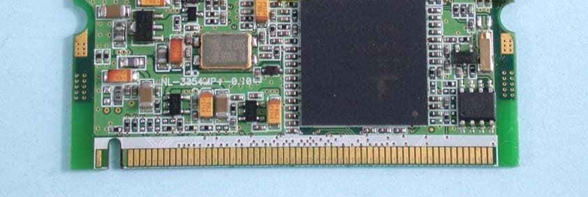
Click to zoom
Application Details
- Equipment Class
- DTS - Digital Transmission System
- Date of Grant
- Oct 26, 2003
- Application Purpose
- Original Equipment
- Date of Application
- Oct 26, 2003
- Equipment Note
- 802.11g Mobile Wireless Mini PCI Adapter
- Frequency Range
- 2412.00000000 - 2462.00000000
- Company
- Senao International Co Ltd
- Country
- Taiwan
Documents & Files
Document Text
Text extracted from the exhibit documents filed with the FCC. Open a document above to read the original.
Users Manual
SENAO High-Speed Wireless MiniPCI Adapter User’s Manual Version: 1.1 High-Speed Wireless MiniPCI AdapterVersion: 1.1 Page 2 of 28 Table of Contents Chapter 1 – Introduction 1.1 Features & Benefits..........................................................................4 1.2 Package Contents............................................................................4 1.3 MiniPCI card Description..........................................................................4 1.4 System Requirements.......................................................................5 1.5 Applications....................................................................................5 1.6 Network Configuration.......................................................................6 Chapter 2 – Drivers & Client Utility 2.1 Before You Begin.............................................................................8 2.2 Installing the MiniPCI card Drivers.............................................................8 2.3 Verify the Installation.......................................................................12 2.4 Disable Windows SSID/WEP Configuration..........................................12 2.5 Using the Client Utility......................................................................14 2.5.1 Wireless Radio On/Off..............................................................15 2.5.2 Remove Status Icon................................................................15 2.5.3 Wireless Network Status...........................................................16 2.5.3.1 Status...................................................................16 2.5.3.2 Configuration..........................................................17 2.5.3.3 Encryption..............................................................18 2.5.3.4 Site Survey.............................................................18 2.5.3.5 IBSS......................................................................19 2.5.3.6 Rates.....................................................................20 2.5.3.7 Domain..................................................................21 2.5.3.8 About.....................................................................21 2.6 Uninstall the Client Utility..................................................................22 Appendix A – Troubleshooting.............................................................25 Appendix B – Product Specifications.....................................................26 Appendix C – Regulatory Compliance Information..................................27 High-Speed Wireless MiniPCI AdapterVersion: 1.1 Page 3 of 28 Revision History VersionDateNotes 1.0September 8, 2003Initial Version 1.1October 2, 2003Updated Screens High-Speed Wireless MiniPCI AdapterVersion: 1.1 Page 4 of 28 1 Introduction This chapter describes the features & benefits, package contents, MiniPCI card description, system requirements, applications, and network configuration. 1.1 Features & Benefits FeaturesBenefits High-speed data rate up to 54 MbpsCapable of handling heavy data payloads such as MPEG video streaming. WEP Data Encryption and TKIPPowerful data security. IEEE 802.1x client support (optional)Enhances authentication and security. Multi-country roaming (802.11d) support Automatically adjusts regulatory domain to operate in different countries. Advanced power managementLow power consumption in power saving mode. TPC (Transmission Power Control) and DFS (Dynamic Frequency Selection) support TPC offers flexibility to adjust RF output power. 1.2 Package Contents h One MiniPCI Card h One Installation CD h One Quick Installation Guide 1.3 System Requirements The following are the minimum system requirements in order to use the MiniPCI card. • PC/AT compatible computer with a PCMCIA Type II slot. • Windows 98/ME/ /2000/XP operating system. • 1.3 MB of free disk space for installing the MiniPCI card driver and utility program. 1.4 Applications The wireless LAN products are easy to install and highly efficient. The following list describes some of the many applications made possible through the power and flexibility of wireless LANs: a) Difficult-to-wire environments There are many situations where wires cannot be laid easily. Historic buildings, older buildings, open areas and across busy streets make the installation of High-Speed Wireless MiniPCI AdapterVersion: 1.1 Page 5 of 28 LANs either impossible or very expensive. b) Temporary workgroups Consider situations in parks, athletic arenas, exhibition centers, disaster- recovery, temporary offices and construction sites where one wants a temporary WLAN established and removed. c) The ability to access real-time information Doctors/nurses, point-of-sale employees, and warehouse workers can access real-time information while dealing with patients, serving customers and processing information. d) Frequently changed environments Show rooms, meeting rooms, retail stores, and manufacturing sites where frequently rearrange the workplace. e) Small Office and Home Office (SOHO) networks SOHO users need a cost-effective, easy and quick installation of a small network. f) Wireless extensions to Ethernet networks Network managers in dynamic environments can minimize the overhead caused by moves, extensions to networks, and other changes with wireless LANs. g) Wired LAN backup Network managers implement wireless LANs to provide backup for mission- critical applications running on wired networks. h) Training/Educational facilities Training sites at corporations and students at universities use wireless connectivity to ease access to information, information exchanges, and learning. High-Speed Wireless MiniPCI AdapterVersion: 1.1 Page 6 of 28 1.5 Network Configuration To better understand how the wireless LAN products work together to create a wireless network, it might be helpful to depict a few of the possible wireless LAN MiniPCI card network configurations. The wireless …
Text truncated - open the document above for the full version.
Cover Letter(s)
FCC ID: NI3-IS-30V16 Report No.921014R03 Modular Approval Request Letter Advance Data Technology Oct. 21, 2003 Dear Application Examiner, SENAO’s IEEE 802.11g Wireless Mini PCI Adapter, FCC ID: NI3-IS-30V16, would like to have your authorization for Module Approval specific to the mobile device such as Access Point or Router. The requirements of Public Notice DA00-1407 have been met and shown on the following statements. 1. “The modular transmitter must have its own RF shielding.”: The radio portion of this module has been shielded, please see exhibition External Photo. 2. “The modular transmitter must have buffered modulation/data inputs.” The EUT has buffered data inputs, it is integrated in chip ISL3880IK. 3. “The modular transmitter must have its own power supply regulation.” There is a regulator in the DC input port, the part number is RT9182ACE. 4. “The modular transmitter must comply with the antenna requirements of section 15.203 and 15.204(C).” The EUT meets the FCC antenna requirements. The spurious emission, unique antenna connector and photo of antennas are shown in the test report. 5. “The modular transmitter must be tested in a stand-alone configuration” The EUT was tested in a stand-alone configuration via a Mimi-PCI to PCMCIA adapter card. Please see section Photographs of Test Configuration in the test report. 6. “The modular transmitter must be labeled with its own FCC ID number.” Please see exhibition Label Sample for the FCC ID of this module. And also in the exhibition Users Manual, there are instructions give to the OEM on how to label the end product. FCC ID: NI3-IS-30V16 Report No.921014R03 7. “The modular transmitter must comply with any specific rule or operating requirements applicable to the transmitter and the manufacturer must provide adequate instructions along with the module to explain any such requirements.” The EUT is compliant with all applicable FCC rules. Detail instructions for maintaining compliance are given in the Users Manual. 8. “The modular transmitter must comply with any applicable RF exposure requirements.” The EUT is compliant with all applicable RF exposure requirements. RF Exposure is addressed in the RF exposure exhibition. Please contact me if you have any further questions. Thanks for your attention. Best Regards, Ellis Wu / Manager Manager of R&TTE Division Advance Data Technology
External Photos
(For Antenna 1) (For Antenna 2)
ID Label/Location Info
Page 1 Label Location
Internal Photos
Page 1 Page 2 Page 3
Operational Description
FCC ID: NI3-IS-30V16 Report No.RF921014R03 Operational Description This device is a IEEE 802.11g Wireless Mini PCI Adapter which operates in the 2.4GHz frequency spectrum with throughput of up to 54Mbps which OFDM technique will be applied. If the signal to noise radio is too poor which could not support 54Mbps, the 11Mbps data rate with CCK technique will be applied. The transmitter of the EUT is powered by host equipment via a PCI interface. The antenna is Dipole antenna with UFL connector and antenna gain is 2dBi. The other instruction, please have a look at the users manual.
RF Exposure Info
FCC ID: NI3-IS-30V16 Report No: RF921014R03 1 RF EXPOSURE REPORT REPORT NO.: RF921014R03 MODEL NO.: SL-3054MP PLUS (for Brand: SENAO) OEM MODEL NO.: NL-3054MP PLUS (for Brand: EnGenius) ACCORDING: FCC Guidelines for Human Exposure IEEE C95.1 APPLICANT: Senao International Co., Ltd. ADDRESS: 2F, No.531, Chung Cheng Rd., Hsin-Tien, Taipei, Taiwan, R.O.C. ISSUED BY: Advance Data Technology Corporation LAB LOCATION: 47 14th Lin, Chiapau Tsun, Linko, Taipei, Taiwan, R.O.C. 0528 ILAC MRA Lab Code: 200102-0 FCC ID: NI3-IS-30V16 Report No: RF921014R03 2 RF Exposure Measurement (Mobile Device) 1. Introduction In this document, we try to prove the safety of radiation harmfulness to the human body for our product. The limit for Maximum Permissible Exposure (MPE) specified in FCC 1.1310 is followed. The Gain of the antenna used in this product is measured in a Fully Anechoic Chamber (FAC) calibrated for antenna measurement in ADT, and also the maximum total power input to the antenna is measured. Through the Friis transmission formula and the maximum gain of the antenna, we can calculate the distance, away from the product, where the limit of MPE is reached. Although the Friis transmission formula is a far field assumption, the calculated result of that is an over-prediction for near field power density. We will take that as the worst case to specify the safety range. 2. RF Exposure Limit According to FCC 1.1310: The criteria listed in the following table shall be used to evaluate the environmental impact of human exposure to radio-frequency (RF) radiation as specified in 1.1307(b) LIMITS FOR MAXIMUM PERMISSIBLE EXPOSURE (MPE) Frequency Range (MHz) Electric Field Strength (V/m) Magnetic Field Strength (A/m) Power Density (mW/cm 2 ) Average Time (minutes) (A)Limits For Occupational / Control Exposures 300-1500......F/3006 1500-100,000......56 (B)Limits For General Population / Uncontrolled Exposure 300-1500......F/15006 1500-100,000......1.030 F = Frequency in MHz FCC ID: NI3-IS-30V16 Report No: RF921014R03 3 3. Friis Formula Friis transmission formula : Pd = (Pout*G) / (4*pi*r 2 ) where Pd = power density in mW/cm 2 Pout = output power to antenna in mW G = gain of antenna in linear scale Pi = 3.1416 R = distance between observation point and center of the radiator in cm If we know the maximum Gain of the antenna and the total power input to the antenna, through the calculation, we will know the MPE value at distance r. Ref. : David K. Cheng, Field and Wave Electromagnetics, Second Edition, Page 640, Eq. (11-133). 4 EUT Operating condition The software provided by Manufacturer enabled the EUT to transmit and receive data at lowest, middle and highest channel individually. 5. Classification This modular is specified to be installed in access point or router which is connected with host through wire. So it is easy to be re-located in the place where at least 20cm far away from the body of the user. Warning statement to the user for keeping at least 20cm or more separation distance with the antenna should be included in users manual. So, this device is classified as Mobile Device. FCC ID: NI3-IS-30V16 Report No: RF921014R03 4 6 Test Results 6.1 Antenna Gain The maximum Gain measured in Fully Anechoic Chamber is 2dBi or 1.58 (numeric). 6.2 Output Power Into Antenna & RF Exposure value at distance 20cm: For CCK technique: Channel Channel Frequency (MHz) Output Power to Antenna (mW) Power Density (mW/cm 2 ) Limit of Power Density (mW/cm 2 ) 12412179.47340.056621.0 62437179.06060.056491.0 112462178.64880.056361.0 For OFDM technique: Channel Channel Frequency (MHz) Output Power to Antenna (mW) Power Density (mW/cm 2 ) Limit of Power Density (mW/cm 2 ) 12412178.23790.056231.0 62437111.68630.035241.0 112462179.47340.056621.0
Test Report
FCC ID: NI3-IS-30V16 Report No.: RF921014R031Issued: Oct. 20, 2003 FCC TEST REPORT REPORT NO.: RF921014R03 MODEL NO.: SL-3054MP PLUS (for Brand: SENAO) OEM MODEL NO.: NL-3054MP PLUS (for Brand: EnGenius) RECEIVED: Oct. 08, 2003 TESTED: Oct. 08 ~ Oct. 17, 2003 APPLICANT: SENAO INTERNATIONAL CO., LTD. ADDRESS: 2F, No.531, Chung Cheng Rd., Hsin-Tien, Taipei, Taiwan, R.O.C. ISSUED BY: Advance Data Technology Corporation LAB LOCATION: 47 14th Lin, Chiapau Tsun, Linko, Taipei, Taiwan, R.O.C. This test report consists of 64 pages in total. It may be duplicated completely for legal use with the approval of the applicant. It should not be reproduced except in full, without the written approval of our laboratory. The client should not use it to claim product endorsement by CNLA, NVLAP or any government agencies. The test results in the report only apply to the tested sample. 0528 ILAC MRA Lab Code: 200102-0 FCC ID: NI3-IS-30V16 Report No.: RF921014R032Issued: Oct. 20, 2003 Table of Contents 1CERTIFICATION ........................................................................................4 2SUMMARY OF TEST RESULTS ................................................................5 3GENERAL INFORMATION.........................................................................6 3.1GENERAL DESCRIPTION OF EUT ...........................................................6 3.2DESCRIPTION OF TEST MODES .............................................................7 3.3GENERAL DESCRIPTION OF APPLIED STANDARDS ............................7 3.4DESCRIPTION OF SUPPORT UNITS .......................................................8 4TEST TYPES AND RESULTS ....................................................................9 4.1CONDUCTED EMISSION MEASUREMENT .............................................9 4.1.1LIMITS OF CONDUCTED EMISSION MEASUREMENT ...........................9 4.1.2TEST INSTRUMENTS................................................................................9 4.1.3TEST PROCEDURES ..............................................................................10 4.1.4TEST SETUP ...........................................................................................10 4.1.5EUT OPERATING CONDITIONS ............................................................. 11 4.1.6TEST RESULTS .......................................................................................12 4.2RADIATED EMISSION MEASUREMENT ................................................18 4.2.1LIMITS OF RADIATED EMISSION MEASUREMENT ..............................18 4.2.2TEST INSTRUMENTS..............................................................................19 4.2.3TEST PROCEDURES ..............................................................................20 4.2.4TEST SETUP ...........................................................................................21 4.2.5EUT OPERATING CONDITIONS .............................................................21 4.2.6TEST RESULTS .......................................................................................22 4.36dB BANDWIDTH MEASUREMENT........................................................29 4.3.1LIMITS OF 6dB BANDWIDTH MEASUREMENT .....................................29 4.3.2TEST INSTRUMENTS..............................................................................29 4.3.3TEST PROCEDURE ................................................................................30 4.3.4TEST SETUP ...........................................................................................30 4.3.5EUT OPERATING CONDITIONS .............................................................30 4.3.6TEST RESULTS ( A )................................................................................31 4.3.7TEST RESULTS ( B ) ...............................................................................35 4.4MAXIMUM PEAK OUTPUT POWER .......................................................39 4.4.1LIMITS OF MAXIMUM PEAK OUTPUT POWER MEASUREMENT ........39 4.4.2TEST INSTRUMENTS..............................................................................39 4.4.3TEST PROCEDURES ..............................................................................40 4.4.4TEST SETUP ...........................................................................................40 4.4.5EUT OPERATING CONDITIONS .............................................................40 4.4.6TEST RESULTS ( A )................................................................................41 4.4.7TEST RESULTS ( B ) ...............................................................................42 4.5POWER SPECTRAL DENSITY MEASUREMENT ...................................43 4.5.1LIMITS OF POWER SPECTRAL DENSITY MEASUREMENT.................43 4.5.2TEST INSTRUMENTS..............................................................................43 4.5.3TEST PROCEDURE ................................................................................44 4.5.4TEST SETUP ...........................................................................................44 FCC ID: NI3-IS-30V16 Report No.: RF921014R033Issued: Oct. 20, 2003 4.5.5EUT OPERATING CONDITIONS .............................................................44 4.5.6TEST RESULTS ( A )................................................................................45 4.5.7TEST RESULTS ( B ) ...............................................................................49 4.6BAND EDGES MEASUREMENT .............................................................53 4.6.1LIMITS OF BAND EDGES MEASUREMENT...........................................53 4.6.2TEST INSTRUMENTS..............................................................................53 4.6.3TEST PROCEDURE ................................................................................53 4.6.4EUT OPERATING CONDITION ...............................................................53 4.6.5EUT OPERATING CONDITION ..........................…
Text truncated - open the document above for the full version.
Test Setup Photos
FCC ID: NI3-IS-30V16 Report No.: RF921014R0361Issued: Oct. 20, 2003 5 PHOTOGRAPHS OF THE TEST CONFIGURATION CONDUCTED EMISSION TEST (Antenna 1) FCC ID: NI3-IS-30V16 Report No.: RF921014R0362Issued: Oct. 20, 2003 FCC ID: NI3-IS-30V16 Report No.: RF921014R0363Issued: Oct. 20, 2003 CONDUCTED EMISSION TEST (Antenna 2) FCC ID: NI3-IS-30V16 Report No.: RF921014R0364Issued: Oct. 20, 2003 FCC ID: NI3-IS-30V16 Report No.: RF921014R0365Issued: Oct. 20, 2003 RADIATED EMISSION TEST (Antenna 1) FCC ID: NI3-IS-30V16 Report No.: RF921014R0366Issued: Oct. 20, 2003 FCC ID: NI3-IS-30V16 Report No.: RF921014R0367Issued: Oct. 20, 2003 RADIATED EMISSION TEST (Antenna 2) FCC ID: NI3-IS-30V16 Report No.: RF921014R0368Issued: Oct. 20, 2003
Contact Information
Applicant
Havin Lu(Director)
Technical Contact
Advance Data Technology CorporationEllis Wu
[email protected]+886 3 327 0910
13-1, Lane 19, WenShan 3rd St · Taoyuan · Taiwan
Test Firm
Bureau Veritas CPS (H.K.) Ltd. Taoyuan BranchRichard Chen
Technical Specifications
| # | Rule Parts | Frequency Range | Power Output |
|---|---|---|---|
| 1 | 15C | 2.41 GHz - 2.46 GHz | 179.00 mW |
Other Applications from Senao International Co Ltd

NI3-SR32106001
Mar 28, 2007Wireless LAN IEEE 802.11b/g Router
Equipment Class
DTS - Digital Transmission System
NI3-MP36006001
Feb 05, 2007IEEE 802.11b/g Wireless Mini-PCI Adaptor
Equipment Class
DTS - Digital Transmission System
NI3-OC86706001
Feb 05, 2007IEEE802.11a/g/b NWH3054A WLAN mini-PCI
Equipment Class
DTS - Digital Transmission System
NI3-OC32106001
May 25, 2006Outdoor 802.11 b/g AP/CB
Equipment Class
DTS - Digital Transmission System
NI3-CB32106001
May 14, 200611g Wireless Multi-Client Bridge/ Router/AP/WDS
Equipment Class
DTS - Digital Transmission System