NIUATLTRCGSM 900/1800/1900 Vehicle Tracking Device
Teletrac Inc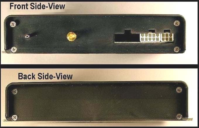
Click to zoom
Application Details
- Equipment Class
- PCB - PCS Licensed Transmitter
- Date of Grant
- Apr 15, 2004
- Application Purpose
- Original Equipment
- Date of Application
- Apr 15, 2004
- Equipment Note
- GSM 900/1800/1900 Vehicle Tracking Device
- Frequency Range
- 1850.20000000 - 1909.80000000
- Company
- Teletrac Inc
- Country
- United States
Documents & Files
Document Text
Text extracted from the exhibit documents filed with the FCC. Open a document above to read the original.
Users Manual
Prism TM Teletrac Prism TM Information and Installation Desired Learning Outcomes At the conclusion of this module you will: Know the physical components that make up a Prism TM installation Know the current feature set of the Prism TM Know the components and processes used to acquire and transmit Prism TM information Know the requirements and processes to install and test a Prism TM Teletrac, Inc. - Prism TM Information and Installation Guide 2 1622-0300 B1 3/18/04 Teletrac, Inc. - Prism TM Information and Installation Guide 1622-0300 B1 3/18/04 3 KEY PERFORMANCE INDICATORS With no direct supervision and with written guidelines, the Prism TM installer will be able to: Describe the peripheral equipment used in a Prism TM installation Identify the internal components that make up a Prism TM Describe the method of how a Prism TM determines its location Identify what information the Prism TM can communicate when different systems are hindered List current features of the Prism TM List the steps to replace a VLU plus with a Prism TM List the steps to initially install a Prism TM Teletrac, Inc. - Prism TM Information and Installation Guide 4 1622-0300 B1 3/18/04 Teletrac, Inc. - Prism TM Information and Installation Guide 1622-0300 B1 3/18/04 5 Table of Contents Introduction .................................................................................................................................................. 7 Physical characteristics ................................................................................................................................ 7 PRISM TM ................................................................................................................................................... 7 ANTENNAS.................................................................................................................................................. 8 PERIPHERALS.............................................................................................................................................. 8 The GPS and GPRS Systems ....................................................................................................................... 9 GLOBAL POSITIONING SYSTEMS (GPS)....................................................................................................... 9 GPRS ........................................................................................................................................................ 14 THE OVERALL TELETRAC PICTURE........................................................................................................... 15 SUBSCRIBER IDENTITY MODULE (SIM) CARD.......................................................................................... 17 Prism TM Functionality............................................................................................................................. 19 DEFAULT SETTINGS................................................................................................................................... 19 Feature Comparison................................................................................................................................... 21 COMPARISON CHART................................................................................................................................21 PRISM TM FEATURES DEFINED................................................................................................................ 22 Long Inbound Messaging ..................................................................................................................... 22 Scheduled Locations ............................................................................................................................. 22 In Motion detection............................................................................................................................... 24 Speed Threshold ................................................................................................................................... 25 Dynamic Power Management .............................................................................................................. 25 Message Store and Forward (Message History) .................................................................................. 26 PRISM TM Installation Instructions .......................................................................................................28 PRE-INSTALLATION CONSIDERATIONS ......................................................................................... 28 ITEMS REQUIRED FOR PRISM TM INSTALLATION.................................................................................... 29 WIRING SCHEMATIC.................................................................................................................................. 29 ANTENNA PLACEMENT.............................................................................................................................. 30 PRISM TM INSTALLATION PROCEDURES................................................................................................ 32 SWAPPING OUT A PRISM TM...................................................................................................................... 34 Prism TM Administration & Provisioning............................................................................................... 36 Appendix A – An Introduction to Global Positioning Satellite Systems................................................ 40 Appendix B – Teletrac Prism TM Antennas ............................................................................................ 50 Appendix C – Installation Equipment ...................................................................................................... 52 Appendix D – How Messages Are Used In Scripts .......................................…
Text truncated - open the document above for the full version.
Cover Letter(s)
CONFIDENTIALITY REQUEST LETTER Federal Communication Commission Equipment Authorization Division, Application Processing Branch 7435 Oakland Mills Road Columbia, MD 21048 April 12, 2004 TO WHOM IT MAY CONCERN Pursuant to Paragraphs §0.457 and 0.459 of the Commission’s Rules (47 C.F.R.) and Section §552(b)(4) of the Freedom of Information Act, Cetecom Inc. on behalf of Teletrac Inc. requests confidentiality for the following products: FCC ID Number Product Model NIUATLTRC Prism TM For the product stated above, we request that the following information be held confidential: 1) Electrical Schematics of the Circuitry 2) Block Diagram 3) PCB layout 4) BOM (Parts List) 5) Operational Description 6) Tune up Procedure No other items submitted as part of the equipment authorization filing process are deemed confidential. The above exhibits contain Teletrac trade secrets and proprietary information that could be of benefit to competitors. This material is not customarily available to the general public and we request that it be withheld from public inspection. If you have any questions, please feel free to contact me at the address shown below. Sincerely, Harpreet Sidhu EMC & Radio Engineer CETECOM, Inc. 411 Dixon Landing Rd. Milpitas, CA 95035 USA
External Photos
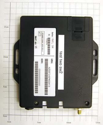
External photos FCC ID: NIUATLTRC EUT Front & Back Views External photos FCC ID: NIUATLTRC EUT – Top view External photos FCC ID: NIUATLTRC EUT – Under side view
ID Label/Location Info
Label location FCC ID: NIUATLTRC Label FCC ID: NIUATLTRC Label location FCC ID: NIUATLTRC Location of Label
Internal Photos
Internal photos FCC ID: NIUATLTRC EUT PCB Top View Internal photos FCC ID: NIUATLTRC EUT – PCB Bottom view Interanl photos FCC ID: NIUATLTRC GSM Module Top view Interanl photos FCC ID: NIUATLTRC GSM Module Bottom view
RF Exposure Info
MPE calculation for: FCC ID: NIUATLTRC Calculations can be made to predict RF field strength and power density levels around typical RF sources using the general equations (3) and (4) on page 19 of the following FCC document: “OET Bulletin 65, Edition 97-01 - Evaluating Compliance with FCC Guidelines for Human Exposure to Radio frequency Electromagnetic Fields”. These equations are generally accurate in the far field of an antenna but will over predict power density in the near field, where they could be used for making a “worst case” prediction. S = PG/4πR 2 (3) Where S = power density (in appropriate units, e.g. mW/cm 2 ) P = power input to the antenna (in appropriate units e.g. mW) G = power gain of the antenna in the direction of interest relative to the isotropic radiator R = distance to the center of radiation of the antenna (appropriate units e.g. cm) or, S = EIRP/4πR 2 (4) Where EIRP = Equivalent Isotropically radiated power Calculation: EIRP: 25.4dBm (346.73mW) Calculated at distance of 20cm Power density = 346.73 / (4 x pi x 20 2 ) = 0.069 mW/cm 2 Limit: 1mW/cm 2 is the reference level for general public exposure according to the OET Bulletin 65, Edition 97-01 Table 1.
Test Report
TTI-P-G 081/94-A0 Accredited according to ISO/IEC 17025 Bluetooth Qualification Test Facility (BQTF) FCC listed # 101450 IC recognized # 3925 CETECOM Inc. 411 Dixon Landing Road Milpitas, CA 95035 U.S.A. Phone: + 1 (408) 586 6200 Fax: + 1 (408) 586 6299 E-mail: [email protected] http://www.cetecom.com CETECOM Inc. is a Delaware Corporation with Corporation number: 2113686 Board of Directors: Dr. Harald Ansorge, Dr. Klaus Matkey, Hans Peter May V1.1 2003-03-01 The BLUETOOTH trademarks are owned by Bluetooth SIG, Inc., U.S.A. and licensed to CETECOM Inc. © Copyright by CETECOM FCC Test Report Test report no.: EMC_551FCC24_2003 FCC Part 24 / RSS 133 Model: Prism TM FCC ID: NIUATLTRC Test report no.: EMC_551FCC24_2003 Issue date: 2004-04-05 Page 2 (36) Table of Contents 1 General information 1.1 Notes 1.2 Testing laboratory 1.3 Details of applicant 1.4 Application details 1.5 Test item 1.6 Test standards 2 Technical test 2.1 Summary of test results 2.2 Test report 1 General information 1.1 Notes The test results of this test report relate exclusively to the test item specified in 1.5. The CETECOM Inc. does not assume responsibility for any conclusions and generalisations drawn from the test results with regard to other specimens or samples of the type of the equipment represented by the test item. The test report may only be reproduced or published in full. Reproduction or publication of extracts from the report requires the prior written approval of the CETECOM Inc. TEST REPORT PREPARED BY: EMC Engineer: Harpreet Sidhu 1.2 Testing laboratory CETECOM Inc. 411 Dixon Landing Road, Milpitas, CA-95035, USA Phone: +1 408 586 6200 Fax: +1 408 586 6299 E-mail: [email protected] Internet: www.cetecom.com Test report no.: EMC_551FCC24_2003 Issue date: 2004-04-05 Page 3 (36) 1.3 Details of applicant Name : Teletrac Inc Street : 7391 Lincoln Way City / Zip Code : Garden Grove CA Country : USA Contact : Frank Cruz Telephone : 714 890 7631 e-mail : [email protected] 1.4 Application details Date of receipt test item : 2003-09-15 Date of test : 2003-09-16/17/18, 2003-10-15 1.5 Test item Manufacturer : Applicant Marketing Name : Prism TM Model No. : Prism TM Description : GSM / GPRS Vehicle Tracking Unit FCC-ID : NIUATLTRC Additional information Frequency : 1850.2MHz – 1909.8MHz for PCS 1900 Type of modulation : GMSK Number of channels : 299 for PCS-1900 Antenna : External Power supply : 12VDC Nominal voltage Output power : 25.4dBm (346.73mW) max. EIRP measured in PCS-1900 Extreme voltage limits : 9.6VDC to 16.5VDC Extreme temp. Tolerance : Lower: -30 o C Upper: +60 o C 1.6 Test standards FCC Part 22,24 / RSS133 r1 Note: All radiated measurements were made in all three orthogonal planes. The values reported are the maximum values. The EUT (Prism TM) carries pre-certified Siemens GSM module model# MC45 with FCC ID: QIPMC45 This test report covers full radiated testing as per FCC 24 on EUT with GSM module. All conducted measurements are covered under test report# 2-20542043b/02 Test report no.: EMC_551FCC24_2003 Issue date: 2004-04-05 Page 4 (36) 2 Technical test 2.1 Summary of test results No deviations from the technical specification(s) were ascertained in the course of the tests Performed Final Verdict: (only “passed” if all single measurements are “passed”) Passed Technical responsibility for area of testing: 2004-04-05 EMC & Radio Siegfried Lehmann (Technical Manager) Date Section Name Signature Responsible for test report and project leader: 2004-04-05 EMC & Radio Harpreet Sidhu (EMC Engineer) Date Section Name Signature Test report no.: EMC_551FCC24_2003 Issue date: 2004-04-05 Page 5 (36) 2.2 Test report TEST REPORT Test report no.: EMC_551FCC24_2003 Model: Prism TM Test report no.: EMC_551FCC24_2003 Issue date: 2004-04-05 Page 6 (36) TEST REPORT REFERENCE PARAMETER TO BE MEASURED PARAGRAPH PAGE POWER OUTPUT §22.913(a) / § 24.232 (b) 7 EMISSION LIMITS TRANSMITTER §2.1051 / §24.238 12 RECEIVER RADIATED EMISSIONS §2.1053 / RSS-133 28 CONDUCTED EMISSIONS §15.107/207 34 TEST EQUIPMENT AND ANCILLARIES USED FOR TESTS 35 BLOCK DIAGRAMS 36 Test report no.: EMC_551FCC24_2003 Issue date: 2004-04-05 Page 7 (36) POWER OUTPUT § 22.913(a) / § 24.232 (b) Summary: During the process of testing, the EUT was controlled via Rhode & Schwarz Universal Radio Communication tester (CMU 200) to ensure max. Power transmission and proper modulation. This paragraph contains EIRP measurements for the EUT. Method of Measurements: The EUT was set up for the max. Output power with pseudo random data modulation. The power was measured with R&S Spectrum Analyzer ESIB 40 (peak) These measurements were done at 3 frequencies, 1850.2 MHz, 1880.0 MHz and 1909.8 MHz (bottom, middle and top of operational frequency range) for PCS-1900 Test report no.: EMC_551FCC24_2003 Issue date: 2004-04-05 Page 8 (36) EIRP (PCS-1900) §24.232(b) Limits: Power Control Level Burst Peak EIRP 0 ≤33dBm (1W) EIRP Burst Peak (dBm) Frequency (MHz) Power Control Level EIRP 1850.2 0 25.40 1880.0 0 24.29 1909.8 0 24.08 Measurement uncertainty ±0.5 dB ANALYZER SETTINGS: RBW = VBW = 3MHz Test report no.: EMC_551FCC24_2003 Issue date: 2004-04-05 Page 9 (36) -20 -10 0 10 20 30 40 Level [dBm] 1.8452G1.848G1.85G1.852G1.8552G Frequency [Hz] Marker: 1.85021002 GHz 25.4 dBm EIRP (PCS-1900) §24.232(b) CHANNEL 512 Test report no.: EMC_551FCC24_2003 Issue date: 2004-04-05 Page 10 (36) -15 -10 0 10 20 30 40 Level [dBm] 1.875G1.878G1.88G1.882G1.885G Frequency [Hz] Marker: 1.88003006 GHz 24.29 dBm EIRP (PCS-1900) §24.232(b) CHANNEL 661 Test report no.: EMC_551FCC24_2003 Issue date: 2004-04-05 Page 11 (36) -20 -10 0 10 20 30 40 Level [dBm] 1.9048G1.908G1.91G1.912G1.9148G Frequency [Hz] Marker: 1.90989018 GHz 24.08 dBm EIRP (PCS-1900) §24.232(b) CHANNEL 810 Test report no.: EMC_551FCC24_2003 Issue date: 2004-04-05 Page 12 (36) EMISSION LIMITS TRANSMITTER §2.1051 / §24.238 Measurement Procedure: The following steps outline the procedure used to measure the radi…
Text truncated - open the document above for the full version.
Test Report
Note: The test results relate only to the individual items which have been tested. This report shall not be reproduced in parts without the written approval of the testing laboratory Applicant:Siemens AG CETECOM - Certification and Testing in Communications GmbH Im Teelbruch 122 D-45219 Essen Germany Telephone: + 49 (0) 20 54 / 95 19 0 Fax: + 49 (0) 2054 / 95 19 20 T E S T R E P O R T No.: 2-20542043b/02 for GPRS/GSM 900/1800/1900 Module MC 45 + DSB 45 + Votronic Handset FCC ID: QIPMC45 TTI-P-G081/94 FCC Registration No. 99538 Test Report 2-20542043b/02, Page 2 of 65 20542043b_02.doc Table of contents 1. SUMMARY OF TEST RESULTS3 2. ADMINISTRATIVE DATA4 2.1. I DENTIFICATION OF THE TESTING LABORATORY 4 2.2. T EST LOCATION 4 2.3. O RGANIZATIONAL ITEMS 4 2.4. A PPLICANT ́ S DETAILS 4 2.5. M ANUFACTURER ́ S DETAILS 4 3. EQUIPMENT UNDER TEST (EUT)5 3.1. EUT: T YPE , S/N ETC . AND SHORT DESCRIPTIONS USED IN THIS TEST REPORT 5 3.2. A UXILIARY E QUIPMENT (AE): T YPE , S/N ETC . AND SHORT DESCRIPTIONS 5 3.3. EUT SET - UPS 6 3.4. EUT OPERATING MODES 6 4. TEST SET-UPS7 4.1. T EST S ET - UP 1 FOR C ONDUCTED MEASUREMENTS 7 4.2. T EST S ET - UP 2 FOR R ADIATED MEASUREMENTS 8 4.3. P ARAMETER SETTINGS ON MOBILE PHONE AND CMU9 5. MEASUREMENTS10 5.1. C ALIBRATION OF ANECHOIC CHAMBER 10 5.2. RF POWER OUTPUT § 2.1046 CONDUCTED 11 5.3. RF POWER OUTPUT § 2.1046 RADIATED 12 5.4. O CCUPIED BANDWIDTH § 2.104913 5.5. S PURIOUS EMISSIONS AT ANTENNA TERMINALS § 2.105117 5.6. F IELD STRENGTH OF SPURIOUS RADIATION § 2.105326 5.7. F REQUENCY STABILITY / TEMPERATURE VARIATION § 2.105550 6. INSTRUMENTS AND ANCILLARY EQUIPMENT „CTC“53 6.1. S INGLE INSTRUMENTS 53 6.2. T EST SYSTEMS 55 7. PHOTOGRAPHS56 7.1. E XTERNAL PHOTOS OF EUT56 7.2. I NTERNAL PHOTOS OF EUT57 7.3. P HOTOS OF TEST SET - UP 59 Test Report 2-20542043b/02, Page 4 of 65 20542043b_02.doc 2. Administrative Data 2.1. Identification of the testing laboratory Company name:CETECOM Certification and Testing in Communications GmbH Address:Im Teelbruch 122 D-45219 Essen - Kettwig Germany Laboratory accreditation:DAR-Registration No.: TTI-P-G081/94 FCC- Registration No.: 99538 Responsible for testing laboratory:Dipl.-Ing. W. Richter Deputies:Dieter Franke Dipl.-Ing. Karin Silberhorn Dipl.-Ing. Heiko Strehlow 2.2. Test location 2.2.1. Test laboratory “CTC” Company name:see chapter 2.1. Identification of the testing laboratory 2.3. Organizational items Reference No.:20542043 Order No.:-- Responsible for test report and project leader:Dipl.-Ing. V. Krueger Receipt of EUT:2002-07-17 Date(s) of test:2002-07-17 – 2002-08-01 Date of report:2002-08-19 Number of report pages:65 Number of diagram pages (annex):no diagrams --------------------------------------------------------------------------------------------------------------------------------------- Version of template: 4.05 2.4. Applicant ́s details Applicant ́s name:Siemens AG Address:Siemensdamm 50 13629 Berlin Germany Contact person:Mr. Hussein Halawi; Tel. +49 30 38630211 2.5. Manufacturer ́s details Manufacturer ́s name:please see Applicant ́s details Address:please see Applicant ́s details Test Report 2-20542043b/02, Page 5 of 65 20542043b_02.doc 3. Equipment under test (EUT) 3.1. EUT: Type, S/N etc. and short descriptions used in this test report short descrip- tion*) EUTType S/N serial number HW hardware status SW software status EUT A GPRS / GSM ModuleMC 4500499941137807 7 B 2.5SW: 34 EUT B Development support box DSB 45# 200B 1.1V 1.0 EUT C Handset VotronicHH-SI-30.3Sample 2V 1.1-- EUT D EUT E EUT F *) EUT short description is used to simplify the identification of the EUT in this test report. Additional Information for EUT A Frequency range:1850.2 – 1909.8 MHz Number of channels:300 Nominal power supply voltage:4,5 V (of module) Power supply range:3,3 – 4,5 V Temperature range:-30°C - +60°C Emission designator:300KGXW Antenna: integral antenna: antenna connector: external antenna Max. stated nominal output power: conducted 30,0 ±2 dBm, radiated 30,0 ±2 dBm EIRP Max. measured output power:conducted 29,7 dBm, radiated 30,6 dBm EIRP 3.2. Auxiliary Equipment (AE): Type, S/N etc. and short descriptions AE short descrip- tion*) Auxiliary EquipmentType S/N serial number HW Hardware status SW software status AE 1 RS 232 cable 1for Com1 - Port--Length=1.81 meter-- AE 2 RS 232 cable 2for Com2 - Port--Length=1.81 meter-- AE 3 AC/DC AdapterMW 1000 GSSample 2Input: 230 V AC, 50 Hz, 28 W Output: 3-6V 9-12 V DC, 1000 mA, 12 VA -- AE 4 GSM Antenna900/ 1800 MHz# 10 dB Gain length=1 meter -- *) AE short description is used to simplify the identification of the auxiliary equipment in this test report. Test Report 2-20542043b/02, Page 6 of 65 20542043b_02.doc 3.3. EUT set-ups EUT set-up no.*) Combination of EUT and AERemarks set. 1EUT A + EUT B + EUT C + AE 1 + AE 2 + AE 3 Set-up for conducted measurements: MC 45 situated outside the DSB45 support-box com-1 cable and com-2 cable connected to DSB-Box but not terminated on the other side (open) set. 2EUT A + EUT B + EUT C + AE 1 + AE 2 + AE 3 + AE 4 Set-up for radiated measurements: MC 45 situated outside the DSB45 support-box com-1 cable and com-2 cable connected to DSB-Box but not terminated on the other side (open) set. 3---- *) EUT set-up no. is used to simplify the identification of the EUT set-up in this test report. 3.4. EUT operating modes EUT operating mode no.*) Description of operating modes Additional information op. 1 IDLE The mobile station is synchronized at the Broadcast Control Channel (BCCH) and listening to the Common Control Channel (CCCH), for details please see chapter: 4.3. Parameter settings on mobile phone and CMU. op. 2 TCH A communication link is established between the mobile station and the test simulator. The transmitter is operated at its maximum rated output power, for details please see chapter: 4.3. Parameter settings on mobile phone and CMU. *) EUT operating mode no. is used to simplify the test report. Test Report 2-20542043b/02, Page 7 of 65 20…
Text truncated - open the document above for the full version.
Test Setup Photos
Test setup photos FCC ID: NIUATLTRC Test setup – Radiated Emissions
Contact Information
Applicant
Darwin Thompson(Director, Engineering)
Test Firm
Cetecom Inc.Lothar Schmidt
Technical Specifications
| # | Rule Parts | Frequency Range | Power Output | Emission | Tolerance |
|---|---|---|---|---|---|
| 1 | 24E | 1.85 GHz - 1.91 GHz | 347.00 mW | 300KGXW | 0.0383000000 ppm |
Other Applications from Teletrac Inc
NIUBTLTRC
May 10, 2006GSM / GPRS Vehicle Tracking Unit
Equipment Class
PCB - PCS Licensed TransmitterNIUCTU-1000
Sep 10, 1997Multilateration System
Equipment Class
LMS - Part 90 Location & Monitoring Transmitter