NIUBTLTRCGSM / GPRS Vehicle Tracking Unit
Teletrac Inc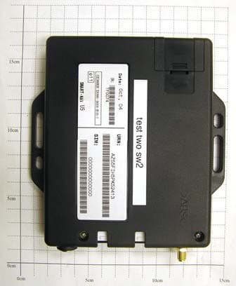
Click to zoom
Application Details
- Equipment Class
- PCB - PCS Licensed Transmitter
- Date of Grant
- May 10, 2006
- Application Purpose
- Original Equipment
- Date of Application
- May 10, 2006
- Equipment Note
- GSM / GPRS Vehicle Tracking Unit
- Frequency Range
- 824.20000000 - 848.80000000
- Company
- Teletrac Inc
- Country
- United States
Documents & Files
Document Text
Text extracted from the exhibit documents filed with the FCC. Open a document above to read the original.
Users Manual
Created on 05/05/2006 Prism TM2 Teletrac Prism TM2 Information and Installation Desired Learning Outcomes At the conclusion of this module you will: Know the physical components that make up a Prism TM2 installation Know the current feature set of the Prism TM2 Know the components and processes used to acquire and transmit Prism TM2 information Know the requirements and processes to install and test a Prism TM2 Teletrac, Inc. - Prism TM2 Information and Installation Guide KEY PERFORMANCE INDICATORS With no direct supervision and with written guidelines, the Prism TM2 installer will be able to: Describe the peripheral equipment used in a Prism TM2 installation Identify the internal components that make up a Prism TM2 Describe the method of how a Prism TM2 determines its location Identify what information the Prism TM2 can communicate when different systems are hindered List current features of the Prism TM2 List the steps to replace a VLU plus with a Prism TM2 List the steps to initially install a Prism TM2 2 1622-0300 B1 5/05/06 Teletrac, Inc. - Prism TM2 Information and Installation Guide Table of Contents Introduction.................................................................................................................................................. 4 Physical characteristics...................................................................................Error! Bookmark not defined. PRISM TM2..........................................................................................ERROR! BOOKMARK NOT DEFINED. ANTENNAS...........................................................................................ERROR! BOOKMARK NOT DEFINED. PERIPHERALS.......................................................................................ERROR! BOOKMARK NOT DEFINED. The GPS and GPRS Systems..........................................................................Error! Bookmark not defined. GLOBAL POSITIONING SYSTEMS (GPS)................................................ERROR! BOOKMARK NOT DEFINED. GPRS...................................................................................................ERROR! BOOKMARK NOT DEFINED. THE OVERALL TELETRAC PICTURE......................................................ERROR! BOOKMARK NOT DEFINED. SUBSCRIBER IDENTITY MODULE (SIM) CARD.....................................ERROR! BOOKMARK NOT DEFINED. Prism TM2 Functionality................................................................................Error! Bookmark not defined. DEFAULT SETTINGS..............................................................................ERROR! BOOKMARK NOT DEFINED. Feature Comparison........................................................................................Error! Bookmark not defined. COMPARISON CHART...........................................................................ERROR! BOOKMARK NOT DEFINED. PRISM TM2 FEATURES DEFINED.........................................................ERROR! BOOKMARK NOT DEFINED. Long Inbound Messaging........................................................................Error! Bookmark not defined. Scheduled Locations................................................................................Error! Bookmark not defined. In Motion detection..................................................................................Error! Bookmark not defined. Speed Threshold......................................................................................Error! Bookmark not defined. Dynamic Power Management.................................................................Error! Bookmark not defined. Message Store and Forward (Message History).....................................Error! Bookmark not defined. PRISM TM2 Installation Instructions..........................................................Error! Bookmark not defined. PRE-INSTALLATION CONSIDERATIONS....................................ERROR! BOOKMARK NOT DEFINED. ITEMS REQUIRED FOR PRISM TM2 INSTALLATION.............................ERROR! BOOKMARK NOT DEFINED. WIRING SCHEMATIC.............................................................................ERROR! BOOKMARK NOT DEFINED. ANTENNA PLACEMENT.........................................................................ERROR! BOOKMARK NOT DEFINED. PRISM TM2 INSTALLATION PROCEDURES.........................................ERROR! BOOKMARK NOT DEFINED. SWAPPING OUT A PRISM TM2...............................................................ERROR! BOOKMARK NOT DEFINED. Prism TM2 Administration & Provisioning..................................................Error! Bookmark not defined. Appendix A – An Introduction to Global Positioning Satellite Systems.....Error! Bookmark not defined. Appendix B – Teletrac Prism TM2 Antennas...............................................Error! Bookmark not defined. Appendix C – Installation Equipment...........................................................Error! Bookmark not defined. Appendix D – How Messages Are Used In Scripts.......................................Error! Bookmark not defined. Appendix E – FCC Statement........................................................................Error! Bookmark not defined. Appendix F - Safety Information...................................................................Error! Bookmark not defined. 1622-0300 B2-5 05 2006 3 Teletrac, Inc. - Prism TM2 Information and Installation Guide INTRODUCTION Welcome to Teletrac’s Prism TM2 Information and Installation Guide. The goal of this guide is to give you an understanding of how the Prism TM2 functions and how the different systems it uses function, as well as, how to install the Prism TM2 itself. As you make your way through this guide, you will start to become familiar with many aspects of the Prism TM2, however, nothing will replace the hands-on experience of installing a unit and seeing how it functions in person. It is hoped that you will use this guide as a refere…
Text truncated - open the document above for the full version.
Users Manual
Teletrac, Inc. - Prism TM2 Information and Installation Guide --------------Unit One-------------- PHYSICAL CHARACTERISTICS P RISM TM2 The Prism TM2 is a custom built transceiver made for Teletrac. The device is a black ABS plastic box roughly the same size as a small CD carrying case. Internally it consists of a GPRS modem, a GPS receiver, a controller board and a SIM card. The GPRS modem and GPS receiver are basically off-the-shelf devices. It’s the SIM card that makes this product unique. The SIM (subscriber identity module) card is a small electronic board that contains the “personality” of the unit. The SIM is a programmable card that can easily be moved from one unit to the next so that in the event of hardware failure the card can be remove and placed in a new unit without any reprogramming. SIM cards and the GPRS system run on the GSM network which is considered to be one of the most secure communication systems since both data and voice are encrypted to prevent eavesdropping. See Section Two for more information about how GSM, GPRS and SIM cards work. In theory, the Prism TM2 should work about the same as a VLU plus . It has been purposefully designed to have a similar wiring scheme and to use the same installed peripherals. See Unit Five for installation information. Teletrac, Inc. - Prism TM2 Information and Installation Guide ANTENNAS The Prism TM2 uses a hidden combo antenna or roof mount combo antenna. In the future there will be more antenna options once the physical connector has changed. Combo Hidden Antenna Roof Mount combo Antenna P ERIPHERALS MDT The Prism TM2 is designed to use the same peripherals or accessories that the RF and CDPD VLU and previous GPRS units uses. In addition to the same peripherals, the Prism TM2 currently has two inputs and one outputs. Input 0 is configured to work with ignition on/off and inputs 1 & 2 allow for the connection of PTOs. 1622-0300 B2-5 05 2006 2
Users Manual
Teletrac, Inc. - Prism TM2 Information and Installation Guide --------------Unit Two-------------- THE GPS AND GPRS SYSTEMS There are two systems that the Prism TM2 uses outside of the Teletrac system. One is the Global Positioning System, more commonly called GPS and the other is the General Packet Radio System otherwise known as GPRS. The following pages will give you a basic introduction to where these systems came from as well as how they work. At the end of this section will be a summary of how Teletrac uses these two systems together to get the location of a vehicle. G LOBAL POSITIONING SYSTEMS (GPS) The following information was taken from information posted to the Teletrac Intranet. Included here is the abridged version of GPS. The full text appears in Appendix A at the end of this Information Guide. AN INTRODUCTION TO GLOBAL POSITIONING SATELLITE SYSTEMS Global Positioning Systems GPS uses "man-made stars" or satellites as reference points to calculate positions on Earth accurate to within meters. In fact, with advanced forms of GPS you can make measurements to better than a centimeter. In a sense, it's like giving every square meter on the planet a unique address. Since GPS receivers have been miniaturized to just a few integrated circuits and have become very economical, the technology has become increasingly accessible. Here's how GPS works in five logical steps: Here is a summary of each of the steps involved with GPS in order to determine a location. This is the first part of Teletrac finding the locations of vehicles using a Prism TM2. Once a location is determined then it is sent via another system. We'll explain each of the following points in the next five sections. 1. The basis of GPS is "triangulation" from satellites. 2. To "triangulate," a GPS receiver measures distance using the travel time of radio signals. 3. To measure travel time GPS needs very accurate timing, which it achieves with some tricks. Teletrac, Inc. - Prism TM2 Information and Installation Guide 4. Along with distance, you need to know exactly where the satellites are in space. High orbits and careful monitoring are the secret. 5. Finally you must correct for any delays the signal experiences as it travels through the aTM2osphere. Step 1: Triangulating from Satellites Improbable as it may seem, the whole idea behind GPS is to use satellites in space as reference points for locations here on earth. That's right, by very, very accurately measuring our distance from three satellites we can "triangulate" our position anywhere on earth. Step 2: Measuring Distance from a Satellite But how can you measure the distance to something that's floating around in space? We do it by timing harrive at our receiver. a sse the le thing boils down to those "velocity times travel time" math problems we did es 60 miles per hour for two hours, how far does it f GPS we're measuring a radio signal so the velocity is going to be the speed of ng the travel time of a radio signal is the key to GPS, then our stop watches had better because if their timing is off by just a thousandth of a second, at the speed of light, n locate a point in 3-dimensional space, then four ow long it takes for a signal sent from the satellite to THE BIG IDEA, MATHEMATICALLY Inen , who in high school. Remember the old: "If a car go travel.?" Velocity (60 mph) x Time (2 hours) = Distance (120 miles) In the case o light, or roughly 186,000 miles per second. Step 3: Getting Perfect Timing If measuri be darn good that translates into almost 200 miles of error! The secret to perfect timing is to make an extra satellite measurement. That's right, if three perfect measurements ca imperfect measurements can do the same thing. 1622-0300 B2-5 05 2006 2 Teletrac, Inc. - Prism TM2 Information and Installation Guide EXTRA MEASUREMENT CURES TIMING OFFSET If everything were perfect (i.e. if our receiver's clocks were perfect) then all of our satellite ranges uld intersect at a singur position). But with imperfect clocks, a fourth ct with the first three. ceiver looks for a to all the rest of its measurements, and now we've got wing Where a Satellite is in Space all GPS receivers have an almanac programmed into their computers that tells the sky each satellite is, moment by moment. tes are constantly onitored by the DeparTM2ent of Defense. They use very precise radar to chs exact altitude, position and speed. wole point (which is o measurement, done as a cross-check, will NOT interse So the receiver's computer says "Uh-oh! There is a discrepancy in my measurements. I must not be perfectly synced with universal time." Since any offset from universal time will affect all of our measurements, the re single correction factor that it can subtract from all its timing measurements that would cause them all to intersect at a single point. That correction brings the receiver's clock back into sync with universal time, and bingo! - you've got atomic accuracy time right in the palm of your hand. Once it has that correction it applies precise positioning. Step 4: Kno On the ground them where in CONSTANT MONITORING ADDS PRECISION The basic orbits are quite exact but just to make things perfect, the GPS satelli m eck each satellite' 1622-0300 B2-5 05 2006 3 Teletrac, Inc. - Prism TM2 Information and Installation Guide GETTING THE MESSAGE OUT Once the DoD has measured a satellite's exact position, they relay that information back up to the satellite itself. The satellite then includes this new corrected position information in the timing signals it's broadcasting. Step 5: Correcting Errors ROUGH TRIP THROUGH THE ATM2OSPHERE First, one of the basic assumptions we've been using throughout this tutorial is not exactly true. We've been saying that you calculate distance to a satellite by multiplying a signal's travel time by the speed of light. But the speed of light is only constant in a vacuum. As a GPS signal passes through the charged particles of the ionosphere and then through …
Text truncated - open the document above for the full version.
Users Manual
Teletrac, Inc. - Prism TM2 Information and Installation Guide SUBSCRIBER IDENTITY MODULE (SIM) CARD Each Subscriber Identity Module is programmed with specific identification features for a unique user, allowing the device that contains a module to be used for such things as online banking and purchasing that require a secure means of identification. They can be swapped between other GSM devices, so the Subscriber Identity Module owner isn't confined to a single device. Teletrac will use the SIM Cards as a quick way to move specific programming information from one location unit to another. The SIM Card will contain information such as location schedules, landmarks, service reminders etc. When the hardware of a locator unit goes bad an installer will replace the hardware and take the SIM Card from the broken device and place it in the new device. This will move all the programmed information and alleviate the need to reprogram units. - --Unit Three-------------- P RISM TM2 FUNCTIONALITY PRISM PRISM 2 PRISM PRISM Can Locate, Message & Send Events Storing of Locations, Events & Messages in a buffer to transmit later Can Message & Send Events, Last Known Good Location is Sent Store Events, Messages & Locates, Last Locate is sent to W/S Teletrac, Inc. - Prism TM2 Information and Installation Guide The Prism TM2 is designed to behave the same way as the VLU plus unit and have the same features available. However, the Prism TM2 is not as programmable as the VLU plus . Instead of having a script, the Prism TM2 has a hard coded set of instructions that can have some small configuration changes. Below is a list of how the unit will act by default; changes to the configuration will be a future implementation. See Unit Four for a description of the features available, as well as, a feature comparison between all the Teletrac units. DEFAULT SETTINGS Default New Power Management: ---- ---- Wait time until unit goes to sleep 4 hours How long should it sleep 4 hours When it wakes, how long should it wait to acquire GPS and CDPD signals 4 minutes Wait time between sending “going to sleep” message and actually going to sleep 6 minute Will the units use Ignition On/Off messaging ---- Y N Will the unit self locate when in coverage ---- Y N How will the unit be located? Workstation or Locate itself ---- Wkstn Itself Location schedule when the vehicle locates itself 15 min / -- miles Maximum speed limit 75 mph Reminder message for exceeding the speed limit (i.e. when a vehicle exceeds the speed limit you will get a message, then, every 5 min that the driver is speeding you will get another message.) 5 minutes Would you like to use Service Mileage? ---- Y N Number of miles between services 3000 miles Number of miles to receive service reminder message 50 miles Will the units use Tow Away messaging ---- Y N If yes, how soon after the vehicle moves should a message be sent 60 seconds The Prism TM2 can also be programmed with landmarks, either rectangles or circles. When a vehicle goes into or out of the zone a message is sent in, no matter what time of day it is. Programming the unit with the Lat/Long of the center then either the radius of the circle or the distance North/South and East/West in meters creates a landmark. 1622-0300 B2-5 05 2006 2 Teletrac, Inc. - Prism TM2 Information and Installation Guide --------------Unit Four-------------- FEATURE COMPARISON Following is a chart to allow you to quickly see each of the features followed by a description of the feature. The chart and feature descriptions are broken down into RF VLU, VLU plus and Prism TM2 features. We will also go over how these features will be implemented to the field. COMPARISON CHART Feature Standard VLU VLU plus Prism Prism TM2 Feature Description Teletrac Towers X Uses the Teletrac RF system of towers to determine locations and transmit information. GPS Locations X X X Uses Global Positioning System to determine locations only. CDPD Connections X Uses Cellular Digital Packet Data Systems to transmit locations, messages and events. GPRS Connection X X Uses General Packet Radio System to transmit locations, messages and events, Low Power Idle Current X Draws a low amount of electricity and places less of a strain on vehicle resources. Dynamic Power Management X X X X Allows for low power consumption Location Store and Forward X X X Can determine location and store for later transmission if out of coverage. Message Store Forward X X X Allows messages to be stored in the unit while out of the coverage area Event Store and Forward X X X Can capture an output event such as ignition on/off and store it for later transmission if out of coverage. Peripherals X X X X Can be used with other Teletrac equipment such as MDTs, SMTs, panic buttons and other Teletrac approved peripherals. Input Configuration X X X X RF VLU, VLU plus & PRISM TM2 can be wired for inputs such as ignition on/off, lift up/down, alarm activation, etc. Long Inbound Messaging X X X Send long inbound messages without additional equipment added to the Teletrac system. Over-the-Air Programming X (optional) X X X Change characteristics by sending information over the airwaves. More comprehensive programming for the VLU plus . Built-in Link Diagnostics X X X Diagnostics connection point. 1622-0300 B2-5 05 2006 3 Teletrac, Inc. - Prism TM2 Information and Installation Guide Scheduled Locations X X X Ability to perform locates based upon a schedule programmed into the unit and downloaded upon request to the workstation. This is in addition to the locates scheduled by the workstation Scheduled Events X X X Used to turn on/off timers or triggers such as Exception Conditions or Ignition on/off In Motion Detection X X X Can determine when it is in motion and act upon the information Zone Compliance X X X Send an alert that a preprogram exception condition has been thrown Speed & Heading Threshold X X X Send an alert that a preprogrammed speed or heading has been exceeded or changed Speed…
Text truncated - open the document above for the full version.
Users Manual
MC46 Siemens Cellular Engine Version: 03.05 DocID: MC46_HD_V03.05 MC46 Hardware Interface Description Confidential / Released s mo b i l e MC46_HD_V03.05 Page 2 of 99 13.11.2003 Document Name: MC46 Hardware Interface Description Version: 03.05 Date: November 13, 2003 DocId: MC46_HD_V03.05 Status: Confidential / Released General Notes Product is deemed accepted by recipient and is provided without interface to recipientís products. The documentation and/or product are provided for testing, evaluation, integration and information purposes. The documentation and/or product are provided on an ìas isî basis only and may contain deficiencies or inadequacies. The documentation and/or product are provided without warranty of any kind, express or implied. To the maximum extent permitted by applicable law, Siemens further disclaims all warranties, including without limitation any implied warranties of merchantability, completeness, fitness for a particular purpose and non-infringement of third-party rights. The entire risk arising out of the use or performance of the product and documentation remains with recipient. This product is not intended for use in life support appliances, devices or systems where a malfunction of the product can reasonably be expected to result in personal injury. Applications incorporating the described product must be designed to be in accordance with the technical specifications provided in these guidelines. Failure to comply with any of the required procedures can result in malfunctions or serious discrepancies in results. Furthermore, all safety instructions regarding the use of mobile technical systems, including GSM products, which also apply to cellular phones must be followed. Siemens or its suppliers shall, regardless of any legal theory upon which the claim is based, not be liable for any consequential, incidental, direct, indirect, punitive or other damages whatsoever (including, without limitation, damages for loss of business profits, business interruption, loss of business information or data, or other pecuniary loss) arising out the use of or inability to use the documentation and/or product, even if Siemens has been advised of the possibility of such damages. The foregoing limitations of liability shall not apply in case of mandatory liability, e.g. under the German Product Liability Act, in case of intent, gross negligence, injury of life, body or health, or breach of a condition which goes to the root of the contract. However, claims for damages arising from a breach of a condition, which goes to the root of the contract, shall be limited to the foreseeable damage, which is intrinsic to the contract, unless caused by intent or gross negligence or based on liability for injury of life, body or health. The above provision does not imply a change on the burden of proof to the detriment of the recipient. Subject to change without notice at any time. The interpretation of this general note shall be governed and construed according to German law without reference to any other substantive law. Copyright Transmittal, reproduction, dissemination and/or editing of this document as well as utilization of its contents and communication thereof to others without express authorization are prohibited. Offenders will be held liable for payment of damages. All rights created by patent grant or registration of a utility model or design patent are reserved. Copyright © Siemens AG 2003 MC46 Hardware Interface Description Confidential / Released s mo b i l e MC46_HD_V03.05 Page 3 of 99 13.11.2003 Contents 0 Document History ...................................................................................................... 7 1 Introduction ................................................................................................................ 8 1.1 Related documents ............................................................................................. 8 1.2 Terms and abbreviations..................................................................................... 9 1.3 Type approval ....................................................................................................12 1.4 Safety precautions .............................................................................................14 2 Product concept........................................................................................................16 2.1 MC46 key features at a glance...........................................................................17 2.2 Circuit concept ...................................................................................................20 3 Application Interface.................................................................................................21 3.1 Operating modes...............................................................................................22 3.2 Power supply.....................................................................................................24 3.2.1 Power supply pins on the board-to-board connector.............................24 3.2.2 Minimizing power losses.......................................................................25 3.2.3 Monitoring power supply.......................................................................25 3.3 Power up / down scenarios ................................................................................26 3.3.1 Turn on MC46 ......................................................................................26 3.3.1.1 Turn on MC46 using the ignition line /IGT (Power on)...............27 3.3.1.2 Timing of the ignition process ...................................................28 3.3.1.3 Turn on MC46 using the POWER signal ...................................29 3.3.1.4 Turn on MC46 using the RTC (Alarm mode).............................29 3.3.2 Turn off MC46 ......................................................................................30 3.3.2.1 Turn off …
Text truncated - open the document above for the full version.
External Photos
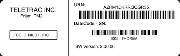
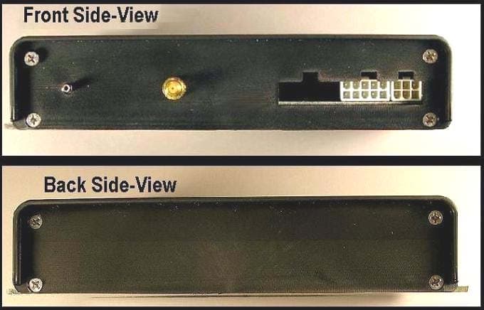
TTI-P-G 081/94-A0 Accredited according to ISO/IEC 17025 Bluetooth Qualification Test Facility (BQTF) FCC listed # 101450 IC recognized # 3925 CETECOM Inc. 411 Dixon Landing Road Milpitas, CA 95035 U.S.A. Phone: + 1 (408) 586 6200 Fax: + 1 (408) 586 6299 E-mail: [email protected] http://www.cetecom.com CETECOM Inc. is a Delaware Corporation with Corporation number: 2113686 Board of Directors: Dr. Harald Ansorge, Dr. Klaus Matkey, Hans Peter May V1.1 2003-03-01 The BLUETOOTH trademarks are owned by Bluetooth SIG, Inc., U.S.A. and licensed to CTECOM Inc. © Copyright by CETECOM External Pictures Model: Teletrac PRISM TM2 FCC ID: NIUBTLTRC Front View Back View Interfaces Antenna Setup
Internal Photos
TTI-P-G 081/94-A0 Accredited according to ISO/IEC 17025 Bluetooth Qualification Test Facility (BQTF) FCC listed # 101450 IC recognized # 3925 CETECOM Inc. 411 Dixon Landing Road Milpitas, CA 95035 U.S.A. Phone: + 1 (408) 586 6200 Fax: + 1 (408) 586 6299 E-mail: [email protected] http://www.cetecom.com CETECOM Inc. is a Delaware Corporation with Corporation number: 2113686 Board of Directors: Dr. Harald Ansorge, Dr. Klaus Matkey, Hans Peter May V1.1 2003-03-01 The BLUETOOTH trademarks are owned by Bluetooth SIG, Inc., U.S.A. and licensed to CTECOM Inc. © Copyright by CETECOM Internal Pictures Model: Teletrac PRISM TM2 FCC ID: NIUBTLTRC Photo 1. Board in chassis Photo 2. Board Top Photo 3. Board Back Photo 4. Board Top Close-up Photo 5. Board Top Module Removed (Note: the shielded component at the bottom of the board is the GPS module. No components are under the GPS module.)
RF Exposure Info
CETECOM Inc. 411 Dixon Landing Road Milpitas, CA 95035 Federal Communication Commission Authorization and Evaluation Division 7435 Oakland Mills Road Columbia, MD 21046 Attention: Reviewing Engineer The Teletrac Prism TM2 is a GSM / GPRS Vehicle Tracking Unit. Due to the construction and the position of the antenna a distance under normal operating conditions of more than 20 cm is guaranteed. Additionally the user manual states: This information includes the following: A minimum separation distance of 20 cm must be maintained between the antenna and the person for this device to satisfy the RF exposure requirements of the FCC. The maximum output power of the Burst 1928 mW (32.85 dBm). Regarding MPE limits, GPUC environment limits maximum exposure to 1 mW/cm 2. The power density is: S = E 2 /3770=-13 H 2 = limit < 1 mW/cm 2 Where: S = Power density (mW/cm 2) E = electrical field strength (V/m) This formula converted using the EIRP is P out *G/4π*r 2 mW/cm 2 1928 /4π*400 = 0.38 mW/cm 2 Calculations are based on standard formula for calculating field strength at a distance and converting power density using free space impedance. If you should have any questions regarding this submission, please feel free to contact the undersigned. Yours truly, Lothar Schmidt Technical Manager EMC/Radio CETECOM Inc.
Test Report
Note: The test results relate only to the individual items which have been tested. This report shall not be reproduced in parts without the written approval of the testing laboratory Applicant:Siemens AG CETECOM - Certification and Testing in Communications GmbH Im Teelbruch 122 D-45219 Essen Germany Telephone: + 49 (0) 20 54 / 95 19 0 Fax: + 49 (0) 2054 / 95 19 20 T E S T R E P O R T No.: 2-20542043b/02 for GPRS/GSM 900/1800/1900 Module MC 45 + DSB 45 + Votronic Handset FCC ID: QIPMC45 TTI-P-G081/94 FCC Registration No. 99538 Test Report 2-20542043b/02, Page 2 of 65 20542043b_02.doc Table of contents 1. SUMMARY OF TEST RESULTS3 2. ADMINISTRATIVE DATA4 2.1. I DENTIFICATION OF THE TESTING LABORATORY 4 2.2. T EST LOCATION 4 2.3. O RGANIZATIONAL ITEMS 4 2.4. A PPLICANT ́ S DETAILS 4 2.5. M ANUFACTURER ́ S DETAILS 4 3. EQUIPMENT UNDER TEST (EUT)5 3.1. EUT: T YPE , S/N ETC . AND SHORT DESCRIPTIONS USED IN THIS TEST REPORT 5 3.2. A UXILIARY E QUIPMENT (AE): T YPE , S/N ETC . AND SHORT DESCRIPTIONS 5 3.3. EUT SET - UPS 6 3.4. EUT OPERATING MODES 6 4. TEST SET-UPS7 4.1. T EST S ET - UP 1 FOR C ONDUCTED MEASUREMENTS 7 4.2. T EST S ET - UP 2…
Text truncated - open the document above for the full version.
Contact Information
Applicant
Darwin Thompson(Director, Engineering)
Technical Contact
CETECOM Inc.Lothar Schmidt
[email protected]408-586-6214
411 Dixon Landing Road · Milpitas, California · United States
Test Firm
Cetecom Inc.Lothar Schmidt
Technical Specifications
| # | Rule Parts | Frequency Range | Power Output | Emission | Tolerance |
|---|---|---|---|---|---|
| 2 | 22H | 824.2 MHz - 848.8 MHz | 1.18 W | 281KGXW | 0.1 ppm |
Other Applications from Teletrac Inc
NIUATLTRC
Apr 15, 2004GSM 900/1800/1900 Vehicle Tracking Device
Equipment Class
PCB - PCS Licensed TransmitterNIUCTU-1000
Sep 10, 1997Multilateration System
Equipment Class
LMS - Part 90 Location & Monitoring Transmitter