NJM0071-029916.5 MHz Data Acqusition Interface
Invocon Inc
Click to zoom
Application Details
- Equipment Class
- DXX - Part 15 Low Power Communication Device Transmitter
- Date of Grant
- Sep 05, 2000
- Application Purpose
- Original Equipment
- Date of Application
- Jun 22, 2000
- Equipment Note
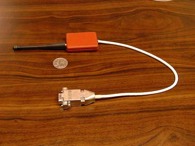
- 916.5 MHz Data Acqusition Interface
- Frequency Range
- 916.50000000 - 916.50000000
- Company
- Invocon Inc
- Country
- United States
Documents & Files

Document Text
Text extracted from the exhibit documents filed with the FCC. Open a document above to read the original.
Users Manual
NJM0071-029 MicroWIS™ User Guide Invocon, Inc. Innovative Concepts in Systems Engineering 2Micro-Wireless Instrumentation System NJM0071-029 © Copyright 2000 Invocon, Inc. DRAFT COPY 19221 I-45 South, Suite 530 Conroe, TX 77385 FCC Notice: The MicroWIS™ Sensor Unit and PC Interface Unit of the MicroWIS system are subject to the following certification. This device complies with part 15 of the FCC Rules. Operation is subject to the following two conditions: (1) This device may not cause harmful interference, and (2) this device must accept any interference received, including interference that my cause undesired operation. CAUTIONARY NOTE TO USER: Changes or modifications to the any piece of equipment in the MicroWIS system are not expressly approved by the manufacturer and could void the user’s authority to operate these units under the Regulations promulgated by the Federal Communications Commission. 3Micro-Wireless Instrumentation System NJM0071-029 DRAFT COPY© Copyright 1999 Invocon, Inc. 19221 I-45 South, Suite 530 Conroe, TX 77385 Document Overview This document will lead you through the steps necessary to collect and view data using the MicroWIS Units. The MicroWIS is manufactured by Invocon, Inc. For more information about this product and other Invocon products please refer to the Contact Information section at the end of this document. Table of contents Page 1.0 Introduction. . . . . . . . . . . . . . . . . . . . . . . . . . . . . . . . . . . . . . 4 2.0 Installation. . . . . . . . . . . . . . . . . . . . . . . . . . . . . . . . . . . . . . 6 3.0 Features. . . . . . . . . . . . . . . . . . . . . . . . . . . . . . . . . . . . . . 6 4.0 A Sample Setup. . . . . . . . . . . . . . . . . . . . . . . . . . . . . . . . . . . .9 5.0 About the Chart program. . . . . . . . . . . . . . . . . . . . . . . . . . . . 9 6.0 View data file with other programs. . . . . . . . . . . . . . . . .. . . 10 4Micro-Wireless Instrumentation System NJM0071-029 © Copyright 2000 Invocon, Inc. DRAFT COPY 19221 I-45 South, Suite 530 Conroe, TX 77385 1.0 INTRODUCTION 1.1 SYSTEM DESCRIPTION The Micro-Wireless Instrumentation System (MicroWIS) is a wireless data acquisition network to measure and transmit temperature data via a wireless link to a transceiver plugged into a PC. A Windows 95 Graphical User Interface allows easy installation, programming, and downloading of data from each unit. The system measures and transmits two temperatures, one on the MicroWIS unit itself, and an external temperature via a two-wire resistive temperature device. A maximum of 32 units, each with a unique node ID can coexist in a single network. A MicroWIS unit’s sample/transmit rate is programmable by the user via setup commands sent from the PC to the transceiver which broadcasts the commands to the units. The measured temperature data is packetized, encoded and sent to the transceiver which decodes and time stamps the data, handles the communication protocol, and sends the data to the PC for plotting and logging. Received temperature data packet is checked and acknowledged for correctness, otherwise the unit will retransmit the data. The remote temperature sensing units will take measurements of both internal and external temperature at sampling intervals according to the latest setup command received from the controller. The external and internal temperatures will be represented with 14-bit and 10-bit resolution respectively. The data packet in addition to these data will include error detection bits and 8-bits to uniquely identify each node. With 8 bits dedicated to the ID field, up to 256 unique IDs are available which are assigned serially and hard coded to the unit during manufacturing and could not be changed by the user. This necessitates reuse of the assigned IDs. The responsibility for preventing a network configured with identical IDs is with the user. This type of setup would result in multiple units with identical IDs to be seen by the controller as a single unit. Such as setup will result in data, which will be hard to interpret because it will be shown as if coming from the same unit. Another concern would be the calibration file which is organized and identified by the unit’s ID. The setup command which basically sets the sample/transmit rate of the remote units, is global. There is no individual or group setting of the sample/transmit rate. Since a network can accommodate up to 32 remote units and they are all set to the same sample/transmit interval, this may imply a high probability of packet collisions at the controller. However, even though the intervals are identical, the transmissions are made asynchronous and randomized by setting the unit’s internal counters reference to a unique start time during manufacturing. Every sensor unit’s internal counter are shipped with a setting equivalent to a default rate of 1sample/minute, and they are transmitting a fixed 5Micro-Wireless Instrumentation System NJM0071-029 DRAFT COPY© Copyright 1999 Invocon, Inc. 19221 I-45 South, Suite 530 Conroe, TX 77385 size packet at a fixed transmission rate of 111000 bps. This essentially limits the transmissions to bursts of roughly 1.1 milliseconds. However, this alone doesn’t eliminate the possibility of collisions at the controller (all sensor units are transmitting asynchronously at the same carrier frequency of 916.5MHz in half-duplex mode). Collision will result in errors on the received packets from the units. The unit’s transmissions require acknowledgment from the controller, If they don’t receive the acknowledgment they will retransmit up to 3 times, but every time their transmit start time will be delayed to minimize the collision probability. The delay duration which is in milliseconds range will be calculated based on a hashing function with the unit’s ID as input to randomize the delays. The sensor units have an internal timer for controlling the wait duration to receive the acknowledgment, which the controller will s…
Text truncated - open the document above for the full version.
Users Manual
2Micro-Wireless Instrumentation System © Copyright 2000 Invocon, Inc. DRAFT COPY 19221 I-45 South, Suite 530 Conroe, TX 77385 FCC Notice: The MicroWIS™ Sensor Unit (FCC ID No. NJM0071-027-028, Model No. 0071-027-028) and the PC Interface Unit (FCC ID No. NJM0071-029, Model No.0071-029) of the MicroWIS system are subject to the following certification. This device complies with part 15 of the FCC Rules. Operatio n is subject to the following two conditions: (1) This device may not cause harmf ul interference, and (2) this device must accept any interference received, including interference that my cause undesired operatio n. Furthermore the MicroWIS™ PC Interface Unit (FCC ID No.NJM0071-029) is also subject to the additional certification: CAUTIONARY NOTE TO USER: Changes or modifications to the any piece of equipment in the MicroWIS system are not expressly approved by the manufacturer and could void the user’s authority to operate these units under the Regulations promulgated by the Federal Communications Commission. This equipment has been tested and found to comply with the limits for a Class B digital device, pursuant to part 15 of the FCC Rules. These limits are designed to provide reasonable protection against harmful interference in a residential installation. This equipment generates, uses and can radiate radio frequency energy and, if not installed and used in accordance with the instructions, may cause harmful interference to radio communications. However, there is no guarantee that interference will not occur in a particular installation. If this equipment does cause harmful interference to radio or television reception, which can be determined by turning the equipment off and on, the user is encouraged to try to correct the interference by one or more of the following measures: • Reorient or relocate the receiving antenna. • Increase the separation between the equipment and receiver. • Connect the equipment into an outlet on a circuit different from that to which the receiver is connected. • Consult the dealer or an experienced radio/TV technician for help. Contact Information for the party responsible for compliance with FCC regulations for the MicroWIS Equipment is provided on Page 12 of this Manual. MicroW IS Model No: 0071-029 FOR HOME OR OFFICE USE Tested to Comply With FCC Standards
Cover Letter(s)
Regarding:Correction to Form 731 Invocon, Inc. FCC ID Number: NJM0071-029 Reference: Form 731, Item 12. When filling out the Form 731, I mistakenly entered 0.25 Watts for item 12, the correct value is 0.00025 Watts. (0.25 milliwatts.) If you could correct this entry, I would appreciate it. Thank you, Ben Bibb, NCE
ID Label/Location Info
Invocon, Inc. 19221 I-45 South, Suite 530 Conroe, TX 77385 The location of the label on the MicroWIS PC Interface Unit will be on the cable of the unit in a font readable without magnification as shown below: FCC ID: NJM0071-029
Operational Description
NJM0071-029 © Copyright 2000 INVOCON, INC. All Rights Reserved. 19221 I-45 South, Suite 530 Conroe, TX 77385 Theory of Operation MicroWIS PC Interface Unit Upon power up, the MicroWIS PC Interface Unit initializes its acknowledge packet buffer with the default sample rate of 1 sample per minute. Next, the radio is put into receive mode and the serial interrupt (from the PC) is enabled. The microprocessor of the MicroWIS PC Interface Unit monitors the radio for incoming RF ASK modulated data with a base-band bit time of 9 micro seconds. Upon reception of data, the processor checks to ensure that the message is a valid data packet. If the data packet is invalid, contains a false node, or fails the CRC check, the processor returns to monitoring the radio for incoming data packets. If the data packet is identified as a valid MicroWIS Sensor data packet, the radio is put into its transmit mode. The PC Interface Unit then ASK transmits with 9 micro second bit times the acknowledge message, containing the current sample rate, addressed to the node that transmitted the data packet. The acknowledge packet transmission takes 1.1 mS. Immediately after transmitting this message, the processor puts the radio back into its receive mode. The data packet is then transmitted at 19.2 kbps via RS-232 to the PC running the MicroWIS Graphical User Interface. The receiver then returns to monitoring the radio for incoming MicroWIS Sensor data packets. Upon an interrupt from the RS-232 serial port, the receiver will monitor the RS-232 port for a command packet transmitted at 19.2 kbps from the MicroWIS Graphical User Interface running on the PC. The processor check the command packet for validity and if it is a valid command packet, updates its sample rate in the acknowledge packet buffer, otherwise it returns to normal operation.
Operational Description
NJM0071-027-029 MicroWIS System Timing The MicroWIS sensor unit sample rate is programmed via the Personal Computer Interface Unit (PCIU). The MicroWIS sensor unit can be programmed using the graphical user interface to acquire and transmit a sample at the following intervals (seconds): 1 2 4 8 16 30 60 120 240 480 960 1800 3600 The MicroWIS sensor unit will send its acquired temperature to the PCIU after a random delay of 12 to 25 milliseconds. This transmission has a duration of 1.134 milliseconds. The sensor unit then switches to “receive” mode for 1.60 milliseconds to listen for an acknowledge. If no acknowledge is received the sensor unit initiates a retransmit sequence that randomly delays for 12 to 25 milliseconds, then retransmits the acquired temperature. This sequence can occur up to four times for each temperature sample. The PCIU acknowledge transmission also has a duration of 1.134 milliseconds. Up to 32 sensor units may communicate with the PCIU. The command to set the sample rate is included in the communication acknowledge message. The sensor unit changes the sample rate, if instructed to do so, immediately after decoding the acknowledge message. The following chart shows timing for valid reception on the first transmission of the sensor unit: Sensor Unit Random Delay Transmit Receive No RF.............. PCIU Listen Receive Acknowledge No RF.............. Timing 12.0 to 25 mS 1.134 mS 1.60 mS Programmed Interval If the PCIU acknowledge message is not received by the sensor unit, the sensor unit will attempt to retransmit after a random delay. The retransmit occurs a maximum of three times. The next chart shows the sequence for an acknowledge message NOT received after the first transmission but successfully received after the second transmission. Sensor Unit Random Delay Transmit Listen Random Delay Transmit Receive PCIU Listen Receive Acknowledge Listen Receive Acknowledge Timing 12.0 to 25 mS 1.134 mS 1.60 mS 12.0 to 25 mS 1.134 mS 1.60 mS
Schematics
Invocon, Inc. 19221 I-45 South, Suite 530 Conroe, TX 77385 Equipment Code: 0071-029 MicroWIS PC Interface Unit RF Portion Schematic Invocon, Inc. Proprietary & Company Confidential Information
Test Report
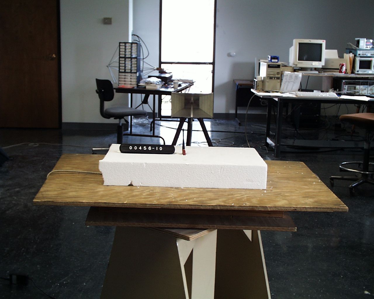
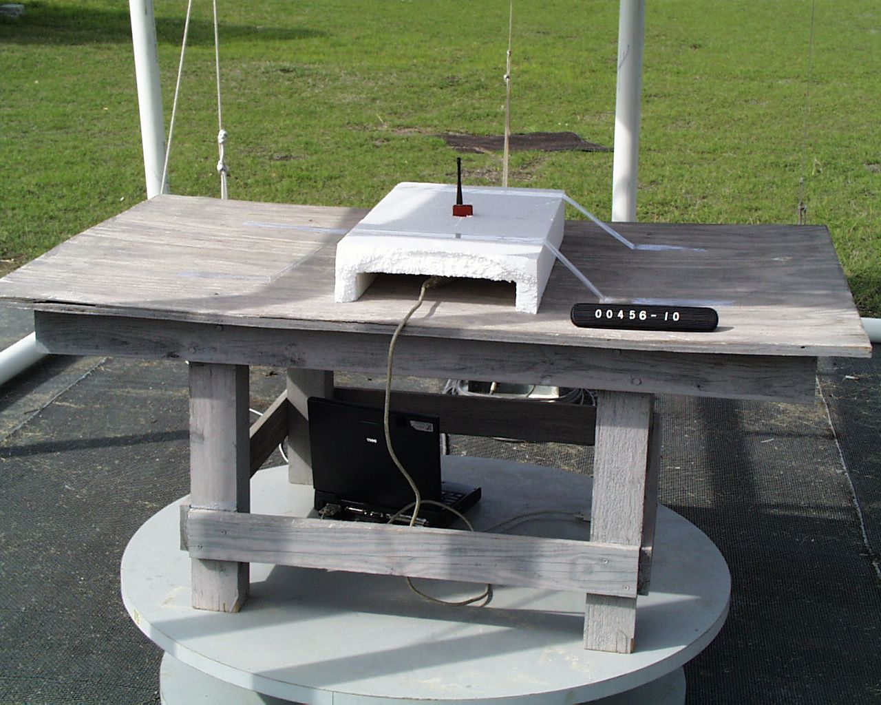
FCC ID# NJM0071-029 Professional Testing (EMI), Inc.Page 2 of 16 Project Number: 00456-10 Prepared for: INVOCON, INC. 19221 IH45 South, Suite 530. Conroe, TX 77385 By Professional Testing (EMI), Inc. 1601 FM 1460, Suite B Round Rock, Texas 78664 June 2000 CERTIFICATION Electromagnetic Interference Test Report INVOCON, INC. MicroWIS PCIU (Intentional Radiator Portion) FCC ID# NJM0071-029 Professional Testing (EMI), Inc.Page 3 of 16 Table of Contents Title Page....................................................................................................................................1 Table of Contents........................................................................................................................2 Certificate of Compliance............................................................................................................3 1.0EUT Description.................................................................................................................4 1.1EUT Operation....................................................................................................................4 2.0Electromagnetic Emissions Testing......................................................................................4 2.2Test Criteria....................................................................................................................5 2.3Test Results.....................................................................................................................5 3.0Occupied Bandwidth Measurements....................................................................................5 3.2Test Criteria....................................................................................................................6 3.3Test Results.....................................................................................................................6 4.0Antenna Requirement..........................................................................................................6 4.1Evaluation Procedure.......................................................................................................6 4.3Evaluation Results...........................................................................................................7 5.0Modifications to Equipment.................................................................................................7 6.0List of Test Equipment........................................................................................................7 Radiated Emissions – Front View............................................................................................4 Radiated Emissions – Back View.............................................................................................4 Figures Figure 1: Radiated Emissions Test Setup.....................................................................................9 Appendices Appendix A: Fundamental Emissions Test Data.........................................................................11 Appendix B: Spurious Emissions Test Data...............................................................................13 Appendix C: Occupied Bandwidth Test Data.............................................................................16 THIS REPORT SHALL NOT BE REPRODUCED EXCEPT IN FULL, WITHOUT THE WRITTEN APPROVAL OF PROFESSIONAL TESTING (EMI), INC. 1601 FM 1460, Suite B Round Rock, Texas 78664 512/244-3371 Fax 512/244-1846 Applicant:INVOCON, Inc. Applicant’s Address: 19221 IH45 South, Suite 530. Conroe, TX 77385 Model:MicroWIS PCIU Serial Number:N/A Project Number:00456-10 Test Dates:08 March 2000, 09 March 2000, and 17 May 2000 I, Jeffrey A. Lenk, for Professional Testing (EMI), Inc., being familiar with the FCC rules and test procedures have reviewed the test setup, measured data and this report. I believe them to be true and accurate. The INVOCON, Inc. MicroWIS PCIU was tested to and found to be in compliance with FCC Part 15 Subpart C for an Intentional Radiator. The highest emissions generated by the above equipment are listed below: Frequency (MHz)Level (dB μV/m)Limit (dBμV/m)Margin (dB) Fundamental916.580.793.9.13.2 Spurious2749.5641.549.58.0 Occupied Bandwidth349kHz ______________________________ Jeffrey A. Lenk President This report has been reviewed and accepted by INVOCON, Inc.. The undersigned is responsible for ensuring that the MicroWIS PCIU will continue to comply with the FCC rules. ______________________________ Certificate of Compliance FCC ID# NJM0071-029 Professional Testing (EMI), Inc.Page 4 of 16 1.0EUT Description The Equipment Under Test (EUT) is the INVOCON, Inc. MicroWIS PCIU. The MicroWIS PCIU is an RS-232 converter. The EUT functions as a transceiver between remote MicroWIS Transmitters. The EUT operates at 916.5 MHz and is designed for compliance with 47 CFR 15.249 of the FCC rules. Specific test requirements for this device include the following: 47 CFR 15.249 Fundamental Transmit Power 47 CFR 15.249(c)/15.209Out of Band Emissions 47 CFR 15.203Antenna Requirement The system tested consisted of the following: Manufacturer & Model Serial #FCC ID #Description INVOCON, Inc. , MicroWIS PCIUN/ANJM0071-029RS-232 converter (PC Interface Unit) 1.1EUT Operation The MicroWIS PCIU was connected to a Laptop PC and transmitted requests for data from a MicroWIS remote transmitter. Setup and operational modes cover worst case configuration and operational modes for the device. The frequency of the transmitting signal is 916.5 MHz. 2.0Electromagnetic Emissions Testing Professional Testing (EMI), Inc. (PTI), follows the guidelines of NIST for all uncertainty calculations, estimates and expressions thereof for EMC testing. Radiated emission measurements were made of the Fundamental and Spurious Emission levels for the MicroWIS PCIU. Measurements of the occupied bandwidth were also made for the equipment. Measurements of the maximum emission levels fo…
Text truncated - open the document above for the full version.
Contact Information
Applicant
Mary Pate
281 292-9903Fax: 281 298-1717
Technical Contact
Invocon, Inc.Michael Walcer
[email protected](281) 292-9903
1601 FM 1460, Suitye B · Conroe, Texas · United States
Non-Technical Contact
Invocon, Inc.Mary Pate
[email protected](281) 292-9903
Test Firm
Professional Testing (EMI), Inc.Jeff Link
Technical Specifications
| # | Rule Parts | Frequency Range | Power Output | Tolerance |
|---|---|---|---|---|
| 1 | 15C | 916.5 MHz - 916.5 MHz | - | ppm |
Other Applications from Invocon Inc

NJM0071-027-028
Aug 08, 2000916.5 MHz Data Acqusition Transciever
Equipment Class
DXT - Part 15 Low Power Transceiver, Rx Verified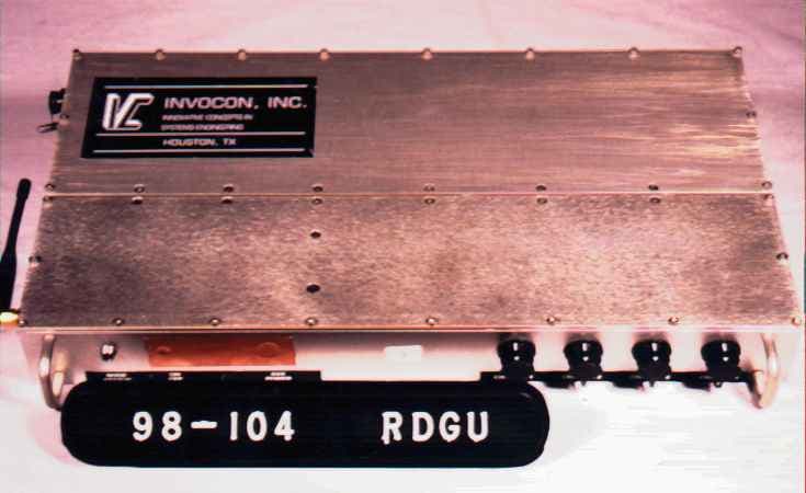
NJM0929156
Sep 14, 1998INVONET Remote Data Gathering Unit (RDGU)
Equipment Class
DSS - Part 15 Spread Spectrum TransmitterNJM0919156
Sep 07, 1998Data Acquisition Transceiver
Equipment Class
DSS - Part 15 Spread Spectrum Transmitter