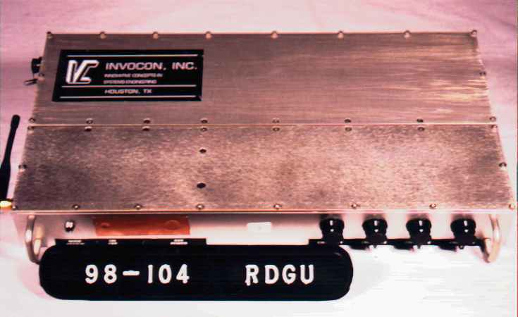
NJM0929156INVONET Remote Data Gathering Unit (RDGU)
Invocon Inc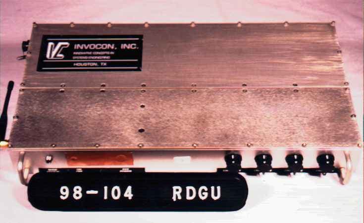
Click to zoom
Application Details
- Equipment Class
- DSS - Part 15 Spread Spectrum Transmitter
- Date of Grant
- Sep 14, 1998
- Application Purpose
- Original Equipment
- Date of Application
- Jul 14, 1998
- Equipment Note
- INVONET Remote Data Gathering Unit (RDGU)
- Frequency Range
- 906.00000000 - 924.00000000
- Company
- Invocon Inc
- Country
- United States
Documents & Files
Document Text
Text extracted from the exhibit documents filed with the FCC. Open a document above to read the original.
Users Manual
INVOCON, INC. 19221 IH 45 South, Suite 530 Conroe, TX 77385 Phone: 281-292-9903 Fax: 281-298-1717 INVONET USER’S MANUAL INVOCON INC. INNOVATIVE CONCEPTS IN SYSTEMS ENGINEERING INVOCON, INC. 19221 IH 45 South, Suite 530 Conroe, TX 77385 Phone: 281-292-9903 Fax: 281-298-1717 Software Installation Instructions 1. Create a working directory on your hard disk drive and install the Invonet software by executing the install command. * Crystal Oscillator Frequencies Network card 16.0 Mhz Data acquisition card 2.0 Mhz, 2.4576 Mhz User Instructions A. Hardware Setup 1. Connect one end of the parallel cable to the operator node, the other to the parallel port of a PC. All units should be installed so that no antenna is within 20 cm of the user. This system must be installed by a trained installer. 2. Invoke the Invonet software by typing “Invonet” and press enter. Turn on the power to the operator node. The screen should display the Invonet logo. Press any key to continue. 3. Turn on the power for any nodes you wish to be active in the network. Press F2 to select the remote nodes you wish to attempt to contact, then press escape. You will be prompted to “Go Configure Network”. Press Y for yes, N for no. If you configure the network, the system will automatically contact the “Remote Data Gathering Units” (RDGU). Upon receiving a response, the screen will display the node number, the TX/RX signal strength, and the routing through the network. Press Esc to continue. You have now contacted and set up the RF link to each unit selected. 4. To enable the analog power of a particular RDGU, press “F5” and select the unit to power up. Upon receiving “Power Up Success” response, you may program the desired data channel for gain factor and set each unit for the desired sample rate. 5. To program the analog front end press “F4”. Select the unit you wish to program from the menu by choosing the corresponding number. Choose the channel you wish to program then select the gain factor from the menu. Gain may differ between channels of one RDGU. From the menu select “Sample Rate” to display a menu of the possible sample rates, then select a sample rate. Once the selections are made, press enter to send the parameters to the RDGU. Wait for the unit to display “Channel Setup Ready”. Proceed as above with the next unit, etc. INVOCON, INC. 19221 IH 45 South, Suite 530 Conroe, TX 77385 Phone: 281-292-9903 Fax: 281-298-1717 Note: Channels which do not have a 350Ω=strain gage attached or have a gage which is improperly installed will not allow that channel to be programmed. Channels which are setup successfully will be indicated by number directly below the RDGU number. 6. To calibrate a channel @ 100 μΕ or test a channel press “F8”. 7. To start data acquisition on selected channels, press the start bracket “[“. To stop the data acquisition and automatically retrieve all the data, press the end bracket “]”. Data file names are generated in the following manner. N2C31041 – Indicates Node 2, Channel 3, 10:41 a.m. N3C41532 –Indicates Node 3, Channel 4, 3:32 p.m. The files are stored in the current working directory. The user may load a data file to view by depressing the “L” key, then the file name. The last data file obtained on a particular channel my be loaded by entering “F” then node number, then channel number. For example, the sequence F53 will load the last data from channel 3 of node 5 on the screen. INVOCON, INC. 19221 IH 45 South, Suite 530 Conroe, TX 77385 Phone: 281-292-9903 Fax: 281-298-1717 The following is a list of available functions. F1 – Help Menu F2 – Select Remote Units to Enter the Network F3 – Deselect All Remote Units F4 – Setup Channels F5 – Power Up Analog Front End F6 – Power Down Analog Front End F7 – Reset Analog Front End F8 – Calibrate or Test a Channel F9 – Show Network Configuration F10 – Configure/Reconfigure Network “[“ – Stop Data Acquisition on Selected Channels “]” – Stop Data Acquisition on Selected Channels “v” – verify RF link between units. “j” – Verify RF link for relayed units. L – Load data file to view. F – Find data file.
Operational Description
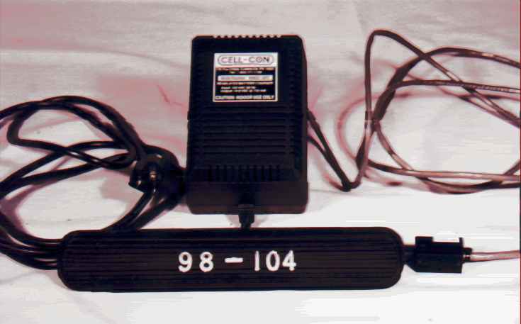
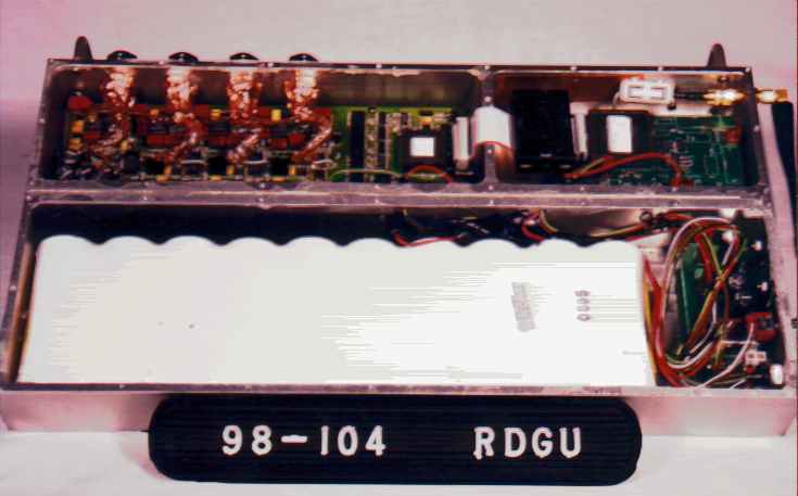
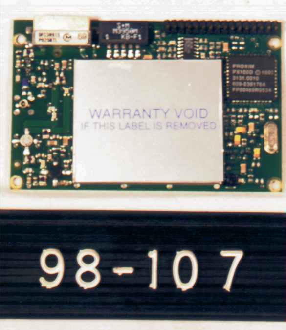
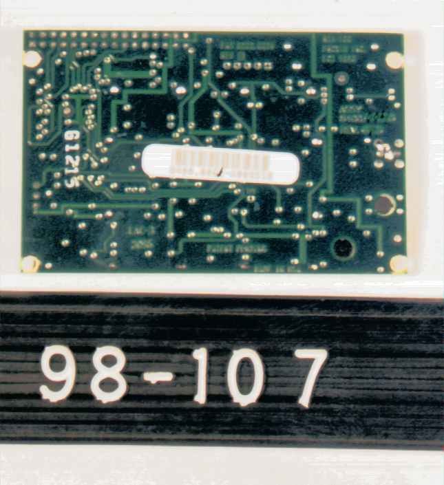
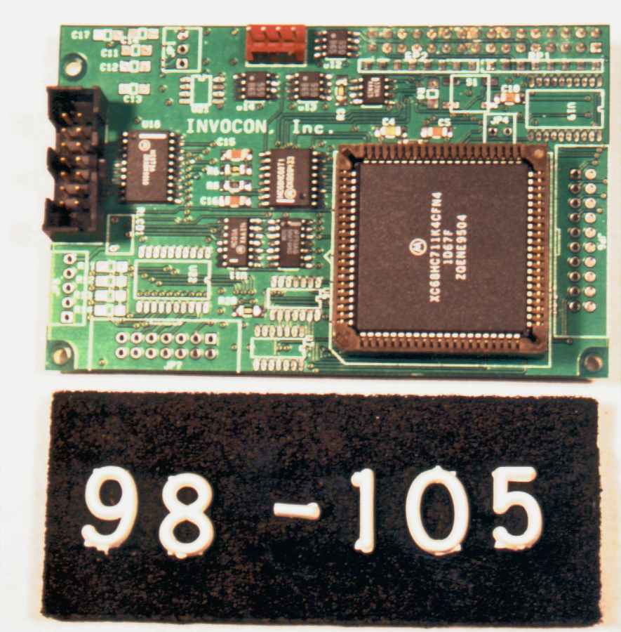
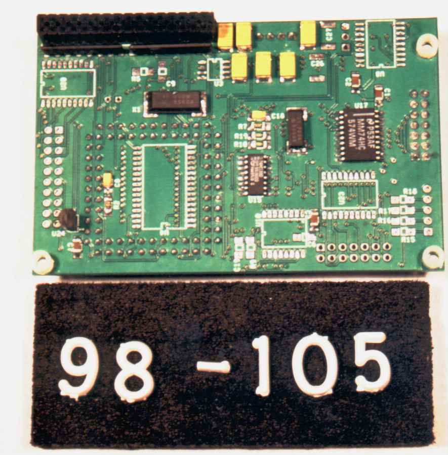
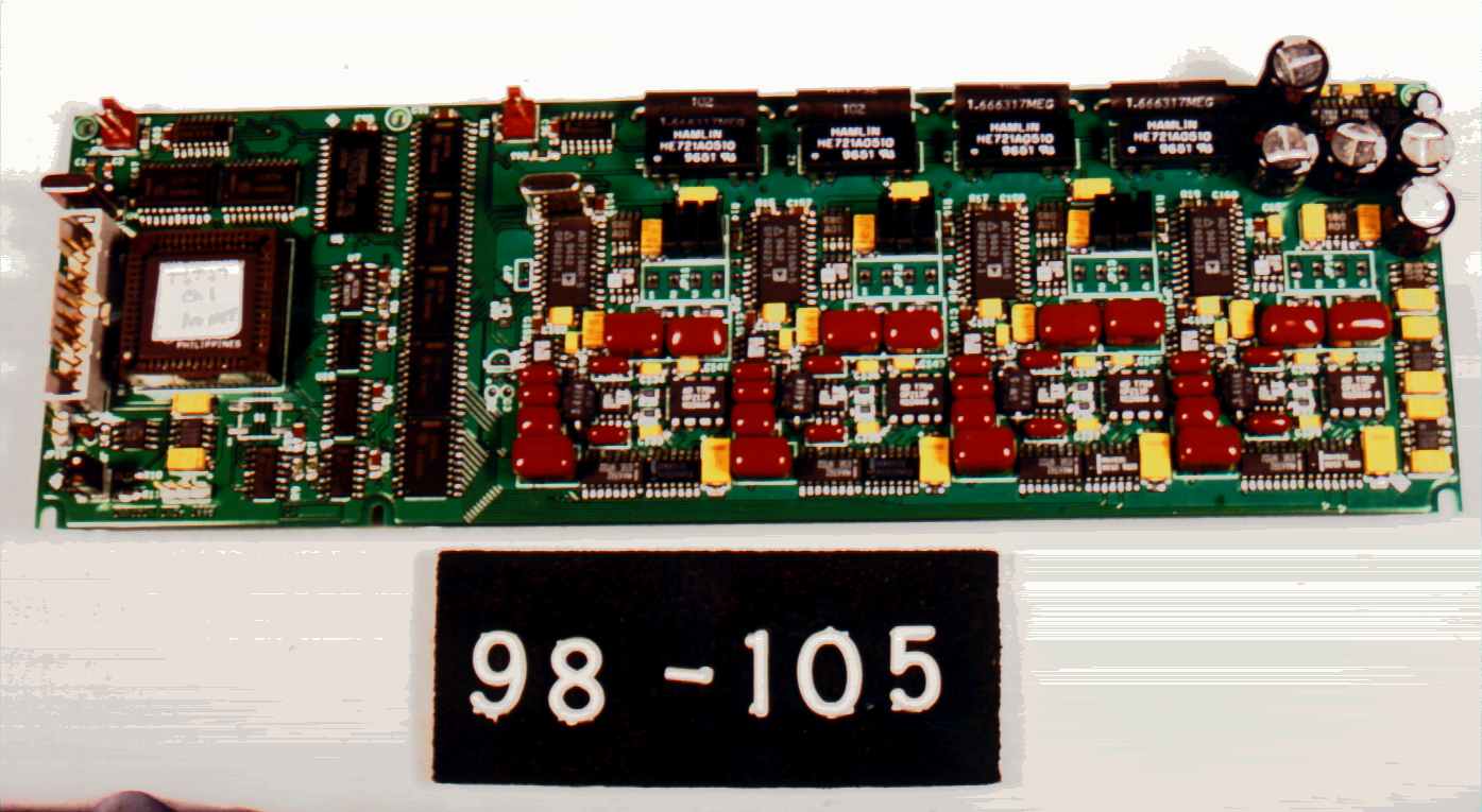
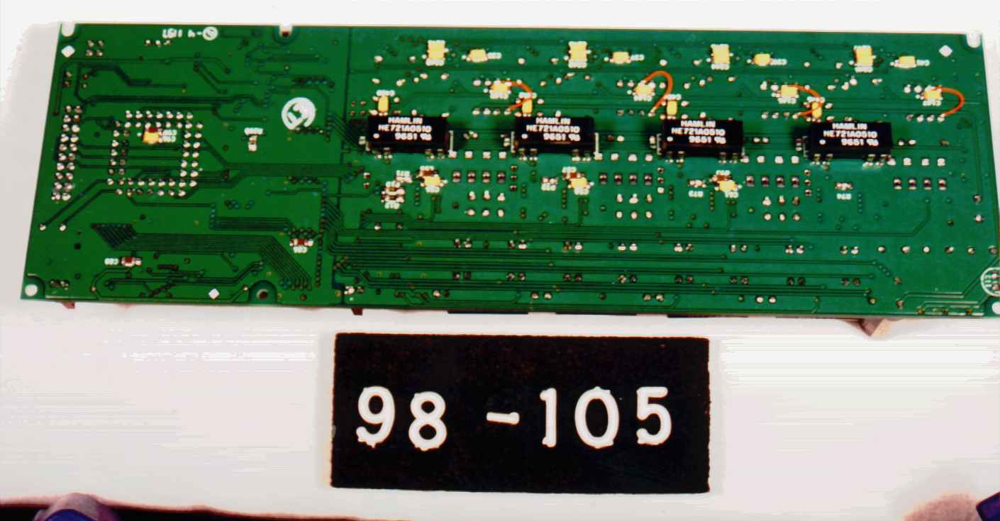
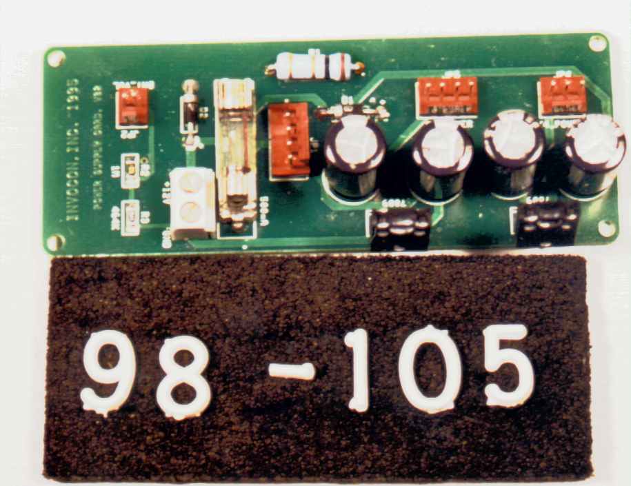
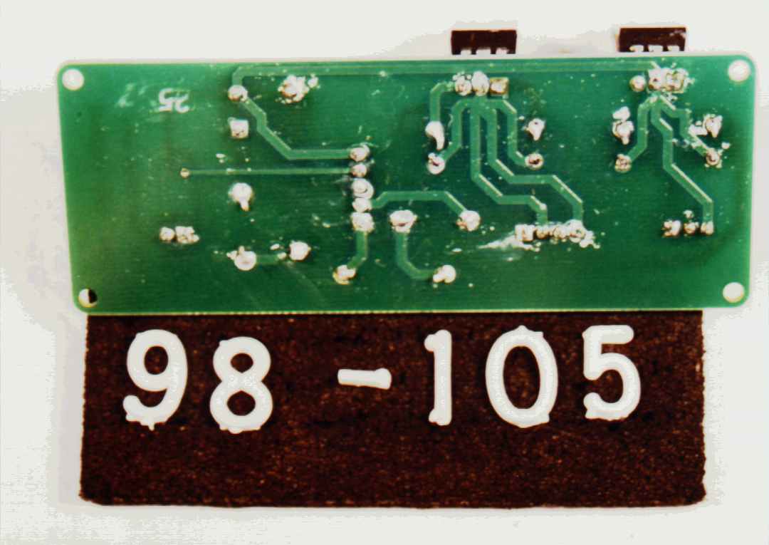
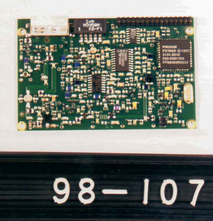
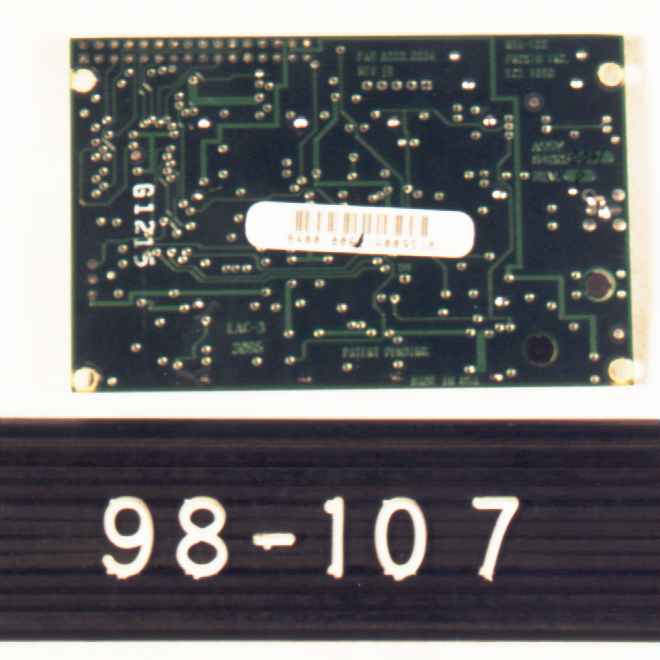
Expository Statement: Item Description INVOCON, Inc. Remote Data Gathering Unit (RDGU) FCC ID# NJM0929156 Description of Equipment The INVONET Wire le ss Data Gathe ring Syste m , designed and manufactured by INVOCON, Inc., is a system used to provide remote monitoring of strain on road bridges. The system is comprised of a control data concentrator unit (CDCU) and a remote data gathering unit (RDGU). The RDGU is fastened to the bridge under test and measures strain on the bridge via a set of strain gauges mounted to the bridge. Data gathered by the RDGU is transmitted to the CDCU upon request from the CDCU. The CDCU is controlled by a standard PC using a parallel interface. The interface between the RDGU and the CDCU is a Proxim transceiver. The Proxim Transceiver is a direct sequence spread spectrum transceiver operating in the 902- 928 MHz band. The RDGU and the CDCU can be powered from a 110 VAC/60 Hz source or from the internal battery. The CDCU is comprised of a transceiver, a network card, and a power supply. The transceiver communicates between the RDGU and the CDCU. The network card is the interface between the external PC and the transceiver. The network card also provides protocol information to allow the CDCU to poll specific RDGU units and manage the data from these units. The power supply supports both units for the CDCU. The RDGU is comprised of a transceiver, a network card , and analog interface section and a power supply. The transceiver performs the interface between the RDGU and the CDCU. The analog interface reads the outputs of the strain gauges and provides the data to the network card. The network card is the interface between the analog interface and the transceiver. This unit also performs the identity function for the RDGU, permitting it to respond to only polls with its specific ID code. The power supply supports both units for the CDCU. The transceivers for both the RDGU and the CDCU are identical. The network cards for the RDGU and the CDCU have identical circuit boards, but are populated slightly differently from each other based on what the application is (RDGU vs. CDCU). Separate verification reports pursuant to Part 15, Subpart B have been prepared for the INVOCON, Inc., Re mote Data Gathe ring Unit (RDGU) as a Digital Device and for the receiver portion of the Remote Data Gathering Unit (RDGU) . A separate report has been filed for the CDCU portion of this system under FCC ID NJM0919156. RF Module Operating Description Data and data synchonization and control signals enter the RF module via the microprocessor bus interface. The synchronization signals are fed to the Phase Lock Loop (PLL) Module while the data is fed to the encryption/scrambler module. This module also integrates the clock into the data stream. The scrambled data signal is routed through spreader and conditioning modules and is then modulated by the PLL module. The final stages of the module amplify the composite signal and route the signal out the antenna. For receive functions, the composite signal is received by the antenna, filtered then amplified. The signal is then downconverted to an IF signal and demodulated. The resulting baseband signal is fed through a despreader and the clock is extracted. The extracted clock is used to descramble the encrypted data signal, producing the original pre-transmitted signal.
RF Exposure Info
FCC APPLICATION ADDITIONAL INFORMATION: FCC ID NJM0929156 INVOCON INVONET RDGU August 12, 1998 1.0 System Operation & Installation The following information was included in the Operational Description provided with the Application: The INVONET Wireless Data Gathering System , designed and manufactured by INVOCON, Inc., is a system used to provide remote monitoring of strain on support members of interstate road bridges. The system is comprised of a control data concentrator unit (CDCU) and a remote data gathering unit (RDGU). The RDGU is fastened to the bridge under test and measures strain on the bridge via a set of strain gauges mounted to the bridge. Data gathered by the RDGU is transmitted to the CDCU upon request from the CDCU. The CDCU is controlled by a standard PC using a parallel interface. The interface between the RDGU and the CDCU is a Proxim transceiver. The Proxim Transceiver is a direct sequence spread spectrum transceiver operating in the 902-928 MHz band. The RDGU and the CDCU can be powered from a 110 VAC/60 Hz source or from the internal battery. 2.0 Discussion Based on standard bridge evaluation procedures, the installation location for bridge monitoring equipment is on a beam or other structural support member out of the way of normal traffic. Based on this criteria, the INVOCON RDGU will be 20 cm away from users based on normal installation procedures for bridge monitoring equipment. Since this installation technique is standard to this industry, specific installation location instructions were not included in the manual. A statement regarding 20 cm isolation is presently included in paragraph A1 of the User’s Manual. If additional wording is required or recommended based on normal bridge testing procedures and the present User’s Manual (i..e. Insure that installation of the RDGU is made such that the antenna is always 20 cm from personnel) please advise us & an addition will be made to the User’s Manual.
Test Report
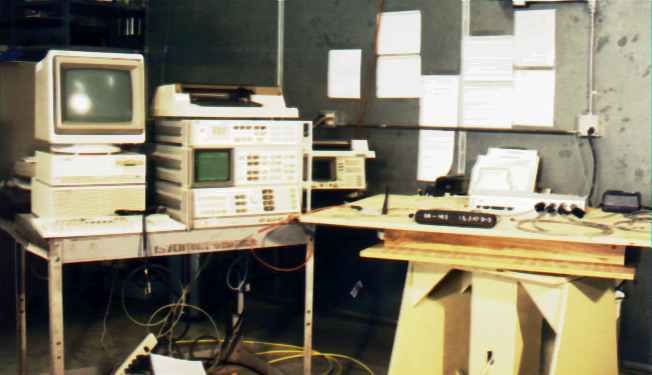
FCC ID# NJM0919156 FCC ID: NJM0929159 Prepared for: INVOCON INC. 9001 I35 South, Suite 530 Conroe, Texas 77385 By: Professional Testing (EMI), Inc. 1601 FM 1460, Suite B Round Rock, Texas 78664 Submitted to: Federal Communications Commission Equipment Approval Services P.O. Box 358315 Pittsburgh, Pennsylvania 15251-3315 April 1998 FCC Application for Type Certification of an Intentional Radiator INVOCON INC. Invonet RDGU Unit Wireless Data Acquisition System (Transmitter Portion) FCC ID# NJM0929156 Professional Testing (EMI), Inc. 2 of 43 Table of Contents Title Page ..............................................................................................................................................1 Table of Contents...................................................................................................................................2 Certificate of Compliance......................................................................................................................4 1.0Equipment Under Test (EUT) Description..................................................................................5 1.1Equipment Under Test (EUT) Operation.....................................................................................6 2.0Minimum Bandwidth Measurements...........................................................................................6 2.1Test Procedure..............................................................................................................................6 2.2Test Criteria..................................................................................................................................6 2.3Test Results...................................................................................................................................6 3.0Peak Output Power Measurements..............................................................................................7 3.1Test Procedure..............................................................................................................................7 3.2Test Criteria..................................................................................................................................7 3.3Test Results...................................................................................................................................7 4.0Spectral Density Measurements...................................................................................................7 4.1Test Procedure..............................................................................................................................8 4.2Test Criteria..................................................................................................................................8 4.3Test Results...................................................................................................................................8 5.0Processing Gain Evaluation..........................................................................................................8 5.1Evaluation Procedure....................................................................................................................8 5.2Evaluation Criteria........................................................................................................................9 5.3Evaluation Results........................................................................................................................9 6.0Out-of-Band Emission Measurements.........................................................................................9 6.1Antenna Conducted Out-of-Band Emission Measurements........................................................9 6.1.1Test Procedure..............................................................................................................................9 6.1.2Test Criteria..................................................................................................................................9 6.1.3Test Results...................................................................................................................................9 6.2Radiated Out-of-Band Emission Measurements........................................................................10 6.2.1Test Procedure............................................................................................................................10 6.2.2Test Criteria................................................................................................................................10 6.2.3Test Results.................................................................................................................................10 7.0Conducted Emissions Measurements.........................................................................................11 7.1Test Procedure............................................................................................................................11 7.2Test Criteria................................................................................................................................11 7.3Test Results.................................................................................................................................11 8.0Frequency Stability Measurements............................................................................................11 8.1Test Procedure............................................................................................................................11 8.2Test Criteria................................................................................................................................12 8.3Test Results.................................................................................................................................12 FCC ID# NJM0929156 Professional Testing (EMI), Inc. 3 of 43 9.0Maximum Permis…
Text truncated - open the document above for the full version.
Contact Information
Applicant
Mary Pate
281 292-9903Fax: 281 298-1717
Technical Contact
Same as bove
Non-Technical Contact
Same as aboveSame as above
Same as above
Test Firm
Professional Testing (EMI) Inc.Jeffrey Lenk
Technical Specifications
| # | Rule Parts | Frequency Range | Power Output |
|---|---|---|---|
| 1 | - | 906 MHz - 924 MHz | 314.00 mW |
Other Applications from Invocon Inc

NJM0071-029
Sep 05, 2000916.5 MHz Data Acqusition Interface
Equipment Class
DXX - Part 15 Low Power Communication Device Transmitter
NJM0071-027-028
Aug 08, 2000916.5 MHz Data Acqusition Transciever
Equipment Class
DXT - Part 15 Low Power Transceiver, Rx VerifiedNJM0919156
Sep 07, 1998Data Acquisition Transceiver
Equipment Class
DSS - Part 15 Spread Spectrum Transmitter