NK4-400011Wireless T1 Modem
io Wave Inc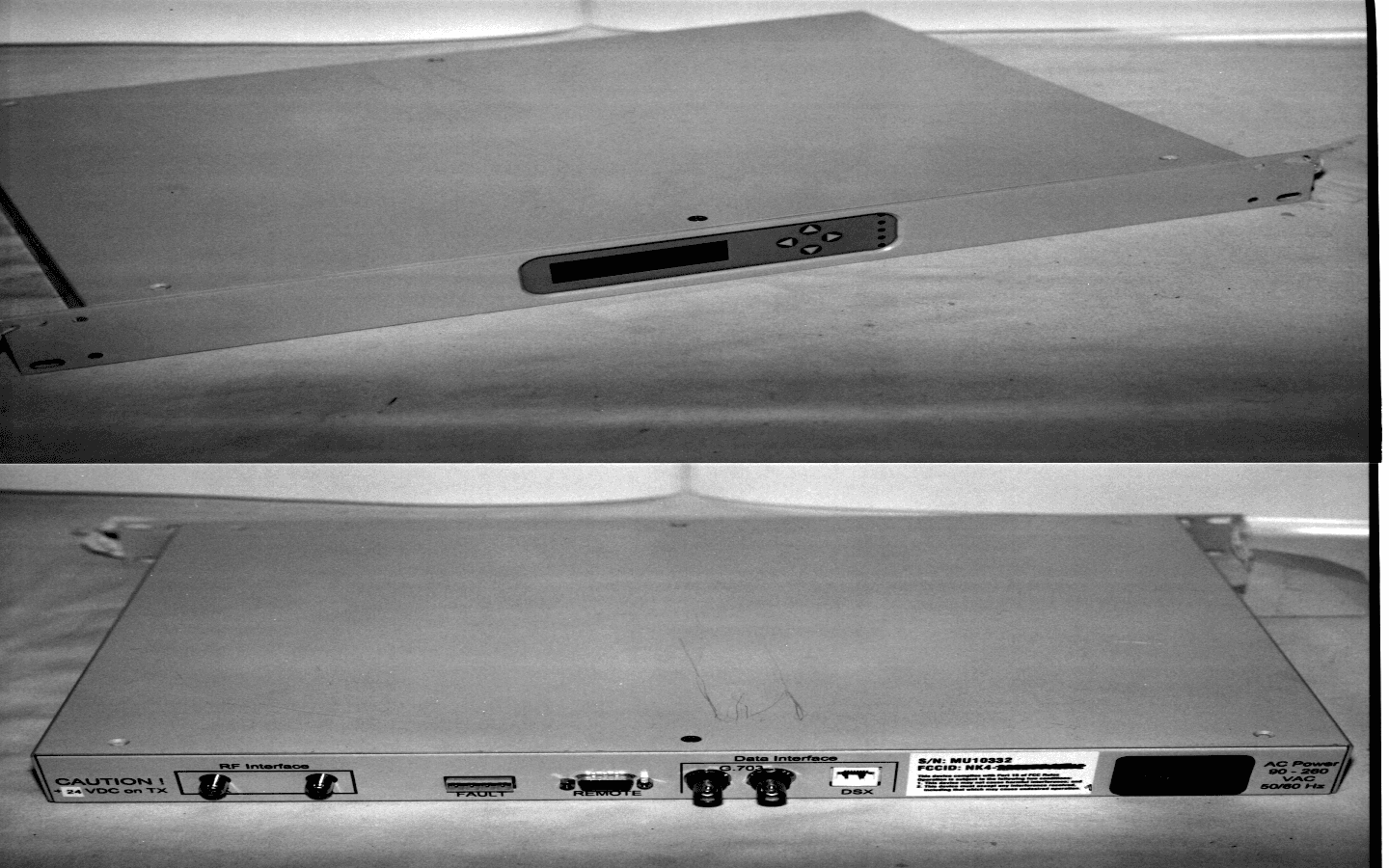
Click to zoom
Application Details
- Equipment Class
- DSS - Part 15 Spread Spectrum Transmitter
- Date of Grant
- May 19, 1999
- Application Purpose
- Original Equipment
- Date of Application
- Feb 09, 1999
- Equipment Note
- Wireless T1 Modem
- Frequency Range
- 5737.50000000 - 5837.50000000
- Company
- io Wave Inc
- Country
- United States
Documents & Files
Document Text
Text extracted from the exhibit documents filed with the FCC. Open a document above to read the original.
Users Manual
5.7 Ghz DRAFT Chapter 2 iolink Product Description The iolink 1.0 is a full duplex Direct Sequence Spread Spectrum (DSSS) device for Tl/El rate wireless communications between two line of sight (LOS) locations. It can be connected to many types of interfaces to meet various communication needs. The technologies incorporated in the iolink 1.0 give you an efficient, minimal interference, error-resistant link Compare to other services and a superior carrier-to-interference (C/1) performance ratio. A. Key Features & Benefits Here are some of the important features and benefits of the iolink 1.0 system: Offers quick turnaround an investment and savings vs. recurring leased line charges Does not require user licensing (complies with FCC regulation Part 15) Provides clear and robust communications over a range of distances is capable of voice, video and data transmissions Operates in precertified 5725 to 5850 Mhz range with 3 channel plans which is virtually immune to atmospheric interference such as rain or snow Provides full duplex Tl (1.544 Mbps) or El (2.048 Mbps) capacity with DSX-1 or G.703 interfaces, respectively Provides forward error correction (FEC), Tl only, for advance warning of potential errors in communication, and alerts the user of changes in the environment that may not have been present during installation which could impact the transmission path Is fully compliant with the simple network management protocol (SNMP) Provides configuration management via the front panel or a PC B. Advanced Features The iolink 1.0 system provides several unique features: Performance monitoring Diagnostic testing The ability to place multiple links in the same area without interference These features allow the user to keep the link up and running with little effort while giving the user a powerful set of diagnostics and statisbcs to detect or troubleshoot potential problems. 1. Performance Monitoring Per-formance monitoring is an important quality control tool. The various statistics the user can obtain from the front panel menus or via a PC can inform how the system is performing. Even though the link is functioning properly, the ability to keep track of link performance allows the user to see changes in the link, which may degrade communications over time. The iolink 1.0 wireless system is fully compliant with the simple network management protocol (SNMP) and provides the user with a performance monitoring system. The system 3 5.7 Ghz DRAFT allows the user or system manager to not only obtain the latest information on link performance, but also allows link performance to be observed over time. The iolink 1.0 management information base (MIB) enables the user to monitor link performance through the network management system (NMS) as well as from the front panel. Statistics for errored seconds, severely errored seconds, unavailable seconds and degraded minutes are automatically tracked. The modem keeps track of these statistics internally for 24 hours at 15 minute intervals. This can help the system manager see if there is anything affecting the link as well as the ability to track times of day when there are more errors in the communication link. 2. Forward Error Correction Alert (Tl Only) As various alarms alert the user of errors in communication or of link failure, the system also provides an alert via forward error correction (FEC). The FEC corrects bit errors, which provides the user with error free performance even when bit errors are occurring during transmission. The system monitors the transmission errors and alerts the user when the rate reaches a preset limit. The user can set this alert to be triggered at a desired level to provide advance warning of potential errors and interference in the link. If the link transmission has a Bit Error Rate (BER) worse than the preset threshold, the system will give a warning. This warning can alert the user to changes in the environment that may not have been present during installation such as new interference, growth of trees, or obstructions that may impact the transmission path so the user can take corrective action. 4 5.7 Ghz DRAFT CHAPTER 3 INS-FALLING YOUR iolink 1.0 SYSTEM This chapter contains everything necessary to get the iolink 1.0 up and running quickly and easily. EQUIPMENT CHECKLIST Your shipment from iowave should include the following components: •The Radio Frequency Unit (also called the "RF unit'@ •The Modem Unit, which acts as the interface between the iolink 1.0 and your existing communications network •The antenna, used to transmit the iolink signal to the other end of the wireless link •The Intermediate Frequency Cable (also called the "IF cable". which connects the modem to the Radio Frequency Unit) •The Radio Frequency Cable (also called the "RF cable". which connects from the Radio Frequency unit and the antenna) If any of the above components is missing from the shipment, please contact iowave customer service at 1-202-333-9283. COMPONENT DESCRIPTIONS RADIO FREQUENCY UNIT The RF unit is the core of the iolink 1.0 system, transmitting and receiving signals at the designated carrier frequency. Compact and weatherproof, the RF unit is designed to be mounted close to the antenna, with flanges on the sides to facilitate mounting on the antenna support structure. The unit is equipped with a grounding stud, which should be used in conjunction with the mounting structure's lightning protection system. The unit communicates with the modem via the Intermediate Frequency (IF) (see below) and is connected to the antenna via the Radio Frequency (RF) Cable (see below). MODEM UNIT The modem unit acts as the interface between the iolink 1.0 and your existing communications network, as well as providing power to the RF unit via the transmit cable. The modem's baseband processor uses iowave's spread spectrum technology to process inbound and outbound signals. iowave's SNMP-compliant network management agent is fully embedded within the m…
Text truncated - open the document above for the full version.
Users Manual
04/99 PRELIMINARY User Guide Technical Reference for ioWave 5.7 GHz Radio Frequency Unit 1010 Wisconsin Avenue • NW • Suite 250 • Washington, DC 20007 Telephone: (202) 333-9283 • Facsimile: (202) 333-0984 • http://www.iowave.com 04/99 PRELIMINARY i Welcome Congratulations on selecting the ioWave 5.7 GHz RF Unit. We value your working with our company, which is now ISO 9001 certified, and encourage you to call us with your comments and suggestions. We look forward to serving you. For more information, contact ioWave at: ioWave, Inc. Technical Support: 1010 Wisconsin Avenue, NWphone: (202) 333-7031 Suite 250fax: (202) 333-0984 Washington, DC 20007e-mail: [email protected] phone: (202) 333-9283 fax: (202) 333-0984 http://www.iowave.com Copyright 1999 by ioWave, Inc . All rights reserved. No part of this manual may be reproduced without express written consent from ioWave . The information contained in this manual is subject to change without notice. PRELIMINARY ii Welcome ............................................................................................................................................i Table of Contents..............................................................................................................................ii Table of Figures ................................................................................................................................ii Table of Tables .................................................................................................................................ii SECTION 1 ioWave 5.7 PRODUCT DESCRIPTION................................................................. 1-1 1.1 Key Features and Benefits of ioWave ........................................................... 1-1 1.2 RF Unit (Outdoor) Description ....................................................................... 1-2 1.3 Operation of the ioWave 5.7 RF Unit ............................................................ 1-4 1.4 How to Contact Us ......................................................................................... 1-5 SECTION 2 INSTALLING THE ioWave 5.7 SYSTEM ............................................................... 2-1 2.1 Site Survey and Path Analysis....................................................................... 2-1 2.1.1 Suitable Antenna ............................................................................... 2-1 2.2 Install the ioWave 5.7 GHz RF Unit............................................................... 2-1 2.3 Connect the RF Cable ................................................................................... 2-2 2.4 Grounding to an Antenna Tower.................................................................... 2-3 2.5 Connect the IF Cables ................................................................................... 2-4 2.5.1 IF Cable Connecting Procedure........................................................ 2-4 APPENDIX A TECHNICAL SPECIFICATIONS FOR ioWave 5.7 ..............................................A-1 APPENDIX B IMPORTANT INFORMATION ABOUT YOUR ioWave SYSTEM .......................B-1 B.1 FCC Regulatory Notice...............................................................................B-1 B.2 Warranty .....................................................................................................B-1 B.3 Disclaimer ...................................................................................................B-3 B.4 Use of ioWave Products Outside of the United States ..............................B-3 Figure 1-1. View of 5.7-GHz RF Unit Connectors ...................................................................... 1-2 Figure 1-2. ioWave 5.7 GHz RF Unit Block Diagram ................................................................. 1-3 Figure 1-3. ioWave 5.7 GHz RF Unit System Overview ............................................................ 1-5 Figure 2-1. RF Unit and RF Cable Installation ........................................................................... 2-2 Figure 2-2. Ground RF Unit to the Tower................................................................................... 2-3 Figure 2-3. Fasten IF Cables to the Tower ................................................................................ 2-4 Table 1-1. ioWave 5.7-GHz RF Unit Frequency Options........................................................... 1-1 Table 1-2. Frequency Plan for 5.7-GHz RF Unit ........................................................................ 1-4 Table A-1. Technical Specifications for ioWave 5.7-GHz RF Unit with ioLink 1 .......................A-1 Table A-1. Technical Specifications for ioWave 5.7-GHz RF Unit with ioLink 4 ...................... A-2 Table of Contents Table of Figures Table of Tables PRELIMINARY Customer Support (202) 333-70311-1 1.1 Key Features and Benefits of ioWave The ioWave 5.7 RF Unit provides many important features and benefits: • Operates in the precertified 5.725-to-5.850 GHz ISM band. • Provides clear and robust voice, video, and data communications for up to 25 miles. • Operates unaffected by rain, snow, fog, and other climatic conditions. • Simplifies troubleshooting IF signal, through separate receive and transmit cables. Another important feature of ioWave products is their scalability. Once a link is installed, users can upgrade a single T1 or E1 link without changing RF Unit, existing cables, or Antenna in order to increase throughput. 1.2 ioWave 5.7 Description The RF Unit is the part of several ioWave systems that transmit, and receive signals at the designated carrier frequency. Compact and weatherproof, is designed for mounting close to the Antenna. The ioWave 5.7 RF Unit is built to provide a single E1 or T1 connection or four multiplexed E1 or T1 connections depending on which modem is utilized. The RF Unit’s three frequency pairs are identified in Table 1-1. Table 1-1. ioWave 5.7 RF Unit Frequency Opti…
Text truncated - open the document above for the full version.
Cover Letter(s)
January 25, 1999 Federal Communications Commission 7435 Oakland Mills Road Columbia, MD 21046 ATTN: Applications Examining Division RE: io Wave, Inc., Certification Application; FCCID: NK4-400011 Gentlemen: Please find the enclosed application for Certification of a Part 15 Direct Sequence Spread Spectrum Transmitter. The Model 5.8 GHz ioLink 1.5 T1 Wireless System will interface with a terminal via RS-232 port, and therefore may be considered a Class A Digital Device as well. Class A is justifiable since the system is intended for, and marketed only to commercial operators. The system has high quality with fast T1 data through-put, as well as being priced way over any consumer product. Commercial applications are outlined in the User Manual on page 3. The 1.26 meter safe distance limit for 1 mW/cm RF exposure, as shown in the user manual page 44, was calculated from FCC OET 65 Appendix B, Table 1B guidlines for General Population/Uncontrolled Exposure. This calculation was based on the highest EIRP possible from the system, considering maximum power and antenna gain. The formula used was: S = (Po*G)/(4*pi*r^2) The RF unit incorporates a standard N connector to the antenna, therefore requiring professional installation. Page 44 of the User Manual specifies that only trained ioWave certified technicians should install the ioLink 1.5. There are many technical steps needed to install an operating full-duplex system, as outlined in the manual. These include antenna support structure, site survey, antenna alignment, test and troubleshoot. All systems sold to businesses are installed by io Wave, Inc. Marketing is limited sales by authorized dealers. Your consideration is much appreciated. Sincerely, Steven Dayhoff Chief Engineer
Cover Letter(s)
February 27, 1999 Federal Communications Commission 7435 Oakland Mills Road Columbia, MD 21046 ATTN: Applications Examining Division RE: io Wave, Inc., Certification Application; FCCID: NK4-400011 Gentlemen: Please find the enclosed amendment for a Part 15 Direct Sequence Spread Spectrum Transmitter. TheModel ioLink 4.0 T2 Wireless Systemis a 5.8 Ghz SST transceiver. The RF unit design is identical with the originally Certified equipment. All changes are in the separate modem unit. The changes made were that of conversion from T1 data rate to T2 data rate capability. A full test report is included along with photos of the new T2 modem unit, schematics, and processing gain measurements. Please consider this as an alternate model for the original ioLink 1.5 T1 model, which will be marketed in addition to this new model. We would like to use the same FCCID for both models, as we are submiting this request prior to approval. You consideration is much appreciated. Sincerely, Steven Dayhoff Chief Engineer
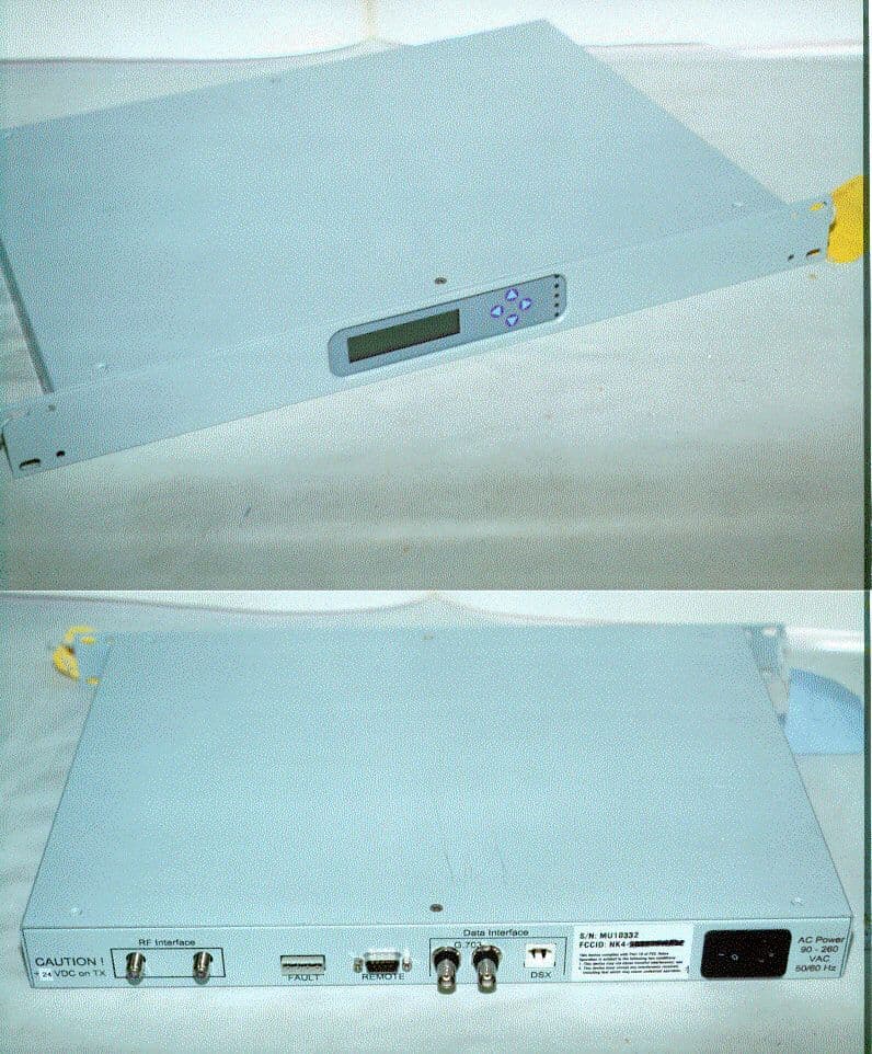
External Photos
MODEM UNIT RF UNIT
Internal Photos
MODEM UNIT - INTERNAL MODEM UNIT - MAIN PCB MODEM UNIT - POWER SUPPLIES RF UNIT - MAIN PCB
RF Exposure Info
WARNING In order to comply with the FCC adopted RF exposure requirements, this transmitter system will be installed by the manufacturer's resaler professional. Installation of the 2 ft. parabolic dish antenna must be performed in a manner that will provide at least 1 .26 meters clearance from the front side of the dish, to any personnel such as employee or member of the public.
Test Report
NATIONAL CERTIFICATION LABORATORY 8370 Court Avenue, Suite B-1 Ellicott City MD 21043 (410) 461-5548 FCC REPORT OF RADIO INTERFERENCE for io Wave, Inc. 1010 Wisconsin Ave., NW Suite 215 Washington, DC 20007 FCC ID: NK4-400011 January 25, 1999 FCC ID #: NK4-400011 2 TABLE OF CONTENTS Application Form 731 FCC Label Drawing and Location 1.0 Introduction 1.1 Summary 2.0 Description of Equipment Under Test (EUT) 3.0Test Program 4.0Test Configuration 5.0 Conducted Emissions Scheme 6.0 Radiated Emissions Scheme TABLES Table 1.Support Equipment Table 2.Interface Cables Table 3. Measurement Equipment EXHIBITS Exhibit 1.EUT Photographs Exhibit 2. Schematic Diagram Exhibit 3. User Manual NCL PROJ.# IOWAVE-484 FCC ID #: NK4-400011 3 1.0 Introduction This report has been prepared on behalf of io Wave, Inc., to support the attached Application for Certification of a Part 15 Spread Spectrum Transmitter. The Equipment Under Test was the 5.8 GHz ioLink 1.5 Wireless Modem Transceiver. Radio-Noise Emissions tests were performed according toFCC Public Notice 54797, titled "Guidance on Measurements for Direct Sequence SST".The measuring equipment conforms to ANSI C63.2 Specifications for Electromagnetic Noise and Field Strength Instrumentation. Testing was performed at National Certification Laboratory in Ellicott City, MD. Site description and site attenuation data have been placed on file with the FCC's Sampling and Measurements Branch. FCC acceptance was granted on May 26, 1993. 1.1 Summary The io Wave, Inc. 5.8 GHz ioLink 1.5 Wireless Modem Transceivercomplies with the FCC limits (15.247) for a Direct Sequence SST. 2.0 Description of Equipment Under Test (EUT) The EUT Features: + 25 dBm RF Output 5737.5 to 5837.5 MHz Freq. Range 25 MHz Channel Bandwidth 3-Channel Sets - Full Duplex Operation DQPSK6-SS Modulation 1.544 MB/s Data Rate (T1) FCC ID #: NK4-400011 4 3.0 Test Program This report contains measurement charts and data as evidence for the following tests performed: 1. (15.247) Peak RF output power. 2. (15.247) Power Spectral Density (3kHz Bandwidth). 3. (15.247) Field strength of harmonics and spurious out-of-band emissions. 4. (15.247) RF Antenna Conducted of harmonics and spurious out-of-band emissions. 5. (15.247) 6 dB Channel Bandwidth. 6. (15.247) Processing Gain. 7. (15.207) Power Line Conducted Emissions. 4.0 Test Configuration RF antenna output tests such as Bandwidth, Spurious/Harmonics, Power output, Power Spectral Density, and Processing Gain, were taken with the transmitter antenna connector feeding directly into the spectrum analyzer or power meter. No external attenuators were used, however the analyzer's internal attenuator was adusted to prevent overloading of the front end. Field strength measurements were taken with the transmitter feeding a 28 dBi gain parabolic dish antenna aimed at the receiving antenna. Full power was developed at the output since a duplex link was not established. FCC ID #: NK4-400011 5 PEAK POWER TEST RESULTS Limit: 1 watt (30 dBm) Readings from RF peak power meter (Carrier Modulated): 5737 MHz - +24.7 dBm 5817 MHz - +25.0 dBm 5837 MHz - +24.8 dBm FCC ID #: NK4-400011 6 POWER SPECTRAL DENSITY Limit: 8 dBm Resolution Bandwidth: 3 kHz Average Time Interval: 1 second/3 kHz Actual Time Interval used for testing: 1.5 seconds/3 kHz Readings from spectrum analyzer: 5737 MHz - +5.1 dBm 5817 MHz - +3.8 dBm 5837 MHz - +1.0 dBm SEE FOLLOWING 3 PLOTS FCC ID #: NK4-400011 7 FCC ID #: NK4-400011 8 FCC ID #: NK4-400011 9 FCC ID #: NK4-400011 10 6 dB Channel Bandwidth Minimum 6 dB BW: 500 kHz RBW Setting on S.A.: 100 kHz Readings from spectrum analyzer: 5737 MHz - 7.1 MHz 5817 MHz - 7.3 MHz 5837 MHz - 7.7 MHz SEE FOLLOWING 3 PLOTS FCC ID #: NK4-400011 11 FCC ID #: NK4-400011 12 FCC ID #: NK4-400011 13 FCC ID #: NK4-400011 14 RF ANTENNA CONDUCTED SPURIOUS/HARMONICS EMISSIONS Limit: 20 dB below Carrier Level RBW Setting on S.A.: 100 kHz SEE FOLLOWING DATA TABLES FCC ID #: NK4-400011 15 FCC PART 15.247 - CONDUCTED SPURIOUS EMISSIONS Frequency of Carrier = 5737.5 MHz Limit = 20 dBc TEST RESULTS LIMIT: -20 dB FROM PEAK CARRIER FCC ID #: NK4-400011 16 COMPONENT FREQUENCY (MHZ)RESULT (dB FROM PEAK) HARMONIC 11475.00 - 44 HARMONIC 17212.50 - 57 HARMONIC 22950.00 - 62 HARMONIC 28687.50 - 69 HARMONIC 34425.00 - 72 FCC PART 15.247 - CONDUCTED SPURIOUS EMISSIONS Frequency of Carrier = 5817.5 MHz Limit = 20 dBc TEST RESULTS LIMIT: -20 dB FROM PEAK CARRIER FCC ID #: NK4-400011 17 COMPONENT FREQUENCY (MHZ)RESULT (dB FROM PEAK) HARMONIC 11635.0 - 46 HARMONIC 17452.5 - 59 HARMONIC 23270.0 - 65 HARMONIC 29087.5 - 69 HARMONIC 34905.0 - 74 FCC ID #: NK4-400011 18 FCC PART 15.247 - CONDUCTED SPURIOUS EMISSIONS Frequency of Carrier = 5837.5 MHz Limit = 20 dBc TEST RESULTS LIMIT: -20 dB FROM PEAK CARRIER COMPONENT FREQUENCY (MHZ) RESULT (dB FROM PEAK) HARMONIC 11675.0 - 45 HARMONIC 17512.5 - 56 HARMONIC 23350.0 - 61 HARMONIC 29187.5 - 67 HARMONIC 35025.0 - 74 FCC ID #: NK4-400011 19 4.0 Test Configuration RADIATED EMISSIONS The EUT was set up on the center of the test table, in a manner which follows the general guidelines of ANSI C63.4, Section 6 "General Operating Conditions and Configurations". This is described below: 5.0 Conducted Emissions Scheme FCC ID #: NK4-400011 20 The EUT is placed on an 80 cm high 1 X 1.5 m non-conductive table. Power to the CPU is provided through a Solar Corporation 50Ω/50 μH Line Impedance Stabilization Network bonded to a 2.2 X 2 meter horizontal ground plane, and a 2.2 X 2 meter vertical ground plane. The LISN has its AC input supplied from a filtered AC power source. A separate LISN provides AC power to the peripheral equipment. I/O cables are moved about to obtain maximum emissions. The 50Ωoutput of the LISN is connected to the input of the spectrum analyzer and emissions in the frequency range of 450 kHz to 30 MHz are searched. The detector function is set to quasi- peak and the resolution bandwidth is set at 9 kHz, with all post-detector filtering no less th…
Text truncated - open the document above for the full version.
Test Report
NATIONAL CERTIFICATION LABORATORY 8370 Court Avenue, Suite B-1 Ellicott City MD 21043 (410) 461-5548 FCC REPORT OF RADIO INTERFERENCE for io Wave, Inc. 1010 Wisconsin Ave., NW Suite 215 Washington, DC 20007 FCC ID: NK4-400011 February 27, 1999 FCC ID #: NK4-400011 2 TABLE OF CONTENTS Application Form 731 FCC Label Drawing and Location 1.0 Introduction 1.1 Summary 2.0 Description of Equipment Under Test (EUT) 3.0Test Program 4.0Test Configuration 5.0 Conducted Emissions Scheme 6.0 Radiated Emissions Scheme TABLES Table 1.Support Equipment Table 2.Interface Cables Table 3. Measurement Equipment EXHIBITS Exhibit 1.EUT Photographs Exhibit 2. Schematic Diagram Exhibit 3. User Manual NCL PROJ.# IOWAVE-484 FCC ID #: NK4-400011 3 1.0 Introduction This report has been prepared on behalf of io Wave, Inc., to support the original Application for Certification of a Part 15 Spread Spectrum Transmitter. The Equipment Under Test was the 5.8 GHz ioLink 4.0 Wireless Modem Transceiver. Radio-Noise Emissions tests were performed according toFCC Public Notice 54797, titled "Guidance on Measurements for Direct Sequence SST".The measuring equipment conforms to ANSI C63.2 Specifications for Electromagnetic Noise and Field Strength Instrumentation. Testing was performed at National Certification Laboratory in Ellicott City, MD. Site description and site attenuation data have been placed on file with the FCC's Sampling and Measurements Branch. FCC acceptance was granted on May 26, 1993. 1.1 Summary The io Wave, Inc. 5.8 GHz ioLink 4.0 Wireless Modem Transceivercomplies with the FCC limits (15.247) for a Direct Sequence SST. 2.0 Description of Equipment Under Test (EUT) The EUT Features: + 25 dBm RF Output 5737.5 to 5837.5 MHz Freq. Range 25 MHz Channel Bandwidth 3-Channel Sets - Full Duplex Operation DQPSK6-SS Modulation Data Rate - (T2) FCC ID #: NK4-400011 4 3.0 Test Program This report contains measurement charts and data as evidence for the following tests performed: 1. (15.247) Peak RF output power. 2. (15.247) Power Spectral Density (3kHz Bandwidth). 3. (15.247) Field strength of harmonics and spurious out-of-band emissions. 4. (15.247) RF Antenna Conducted of harmonics and spurious out-of-band emissions. 5. (15.247) 6 dB Channel Bandwidth. 6. (15.247) Processing Gain. 7. (15.207) Power Line Conducted Emissions. 4.0 Test Configuration RF antenna output tests such as Bandwidth, Spurious/Harmonics, Power output, Power Spectral Density, and Processing Gain, were taken with the transmitter antenna connector feeding directly into the spectrum analyzer or power meter. No external attenuators were used, however the analyzer's internal attenuator was adusted to prevent overloading of the front end. Field strength measurements were taken with the transmitter feeding a 28 dBi gain parabolic dish antenna aimed at the receiving antenna. Full power was developed at the output since a duplex link was not established. FCC ID #: NK4-400011 5 PEAK POWER TEST RESULTS Limit: 1 watt (30 dBm) Readings from RF peak power meter (Carrier Modulated): 5737 MHz - +25.3 dBm 5817 MHz - +25.0 dBm 5837 MHz - +25.2 dBm FCC ID #: NK4-400011 6 POWER SPECTRAL DENSITY Limit: 8 dBm Resolution Bandwidth: 3 kHz Average Time Interval: 1 second/3 kHz Actual Time Interval used for testing: 1.5 seconds/3 kHz Readings from spectrum analyzer: 5737 MHz - +5.1 dBm 5817 MHz - +5.0 dBm 5837 MHz - +5.4 dBm SEE FOLLOWING 3 PLOTS FCC ID #: NK4-400011 7 POWER SPECTRAL DENSITY PLOT TOP REFERENCE LEVEL: 30 dBm RESOLUTION BW: 3 kHz CENTER FREQUENCY: 5737.5 MHZ FREQUENCY SPAN: 2 MHZ SWEEP TIME: 100 SEC/DIV PEAK LEVEL: 5.1 dBm FCC ID #: NK4-400011 8 POWER SPECTRAL DENSITY PLOT TOP REFERENCE LEVEL: 30 dBm RESOLUTION BW: 3 kHz CENTER FREQUENCY: 5817.5 MHZ FREQUENCY SPAN: 2 MHZ SWEEP TIME: 100 SEC/DIV PEAK LEVEL: 5.0 dBm FCC ID #: NK4-400011 9 FCC ID #: NK4-400011 10 POWER SPECTRAL DENSITY PLOT TOP REFERENCE LEVEL: 30 dBm RESOLUTION BW: 3 kHz CENTER FREQUENCY: 5837.5 MHZ FREQUENCY SPAN: 2 MHZ SWEEP TIME: 100 SEC/DIV PEAK LEVEL: 5.4 dBm FCC ID #: NK4-400011 11 FCC ID #: NK4-400011 12 6 dB Channel Bandwidth Minimum 6 dB BW: 500 kHz RBW Setting on S.A.: 100 kHz Readings from spectrum analyzer: 5737 MHz - 10.1 MHz 5817 MHz - 10.8 MHz 5837 MHz - 10.3 MHz SEE FOLLOWING 3 PLOTS FCC ID #: NK4-400011 13 6 dB CHANNEL BANDWIDTH PLOT TOP REFERENCE LEVEL: 30 dBm RESOLUTION BW: 100 KHZ CENTER FREQUENCY: 5737.5 MHZ FREQUENCY SPAN: 50 MHZ (5 MHZ/DIV) MEASURED BANDWIDTH: 10.1 MHZ FCC ID #: NK4-400011 14 6 dB CHANNEL BANDWIDTH PLOT TOP REFERENCE LEVEL: 30 dBm RESOLUTION BW: 100 KHZ CENTER FREQUENCY: 5817.5 MHZ FREQUENCY SPAN: 50 MHZ (5 MHZ/DIV) MEASURED BANDWIDTH: 10.8 MHZ FCC ID #: NK4-400011 15 FCC ID #: NK4-400011 16 6 dB CHANNEL BANDWIDTH PLOT TOP REFERENCE LEVEL: 30 dBm RESOLUTION BW: 100 KHZ CENTER FREQUENCY: 5837.5 MHZ FREQUENCY SPAN: 50 MHZ (5 MHZ/DIV) MEASURED BANDWIDTH: 10.3 MHZ FCC ID #: NK4-400011 17 FCC ID #: NK4-400011 18 RF ANTENNA CONDUCTED SPURIOUS/HARMONICS EMISSIONS Limit: 20 dB below Carrier Level RBW Setting on S.A.: 100 kHz SEE FOLLOWING DATA TABLES FCC ID #: NK4-400011 19 FCC PART 15.247 - CONDUCTED SPURIOUS EMISSIONS Frequency of Carrier = 5737.5 MHz Limit = 20 dBc TEST RESULTS LIMIT: -20 dB FROM PEAK CARRIER COMPONENT FREQUENCY (MHZ)RESULT (dB FROM PEAK) HARMONIC 11475.00 - 46 HARMONIC 17212.50 - 62 HARMONIC 22950.00 - 65 HARMONIC 28687.50 - 71 HARMONIC 34425.00 - 74 FCC ID #: NK4-400011 20 FCC PART 15.247 - CONDUCTED SPURIOUS EMISSIONS Frequency of Carrier = 5817.5 MHz Limit = 20 dBc TEST RESULTS LIMIT: -20 dB FROM PEAK CARRIER COMPONENT FREQUENCY (MHZ)RESULT (dB FROM PEAK) HARMONIC 11635.0 - 47 HARMONIC 17452.5 - 59 HARMONIC 23270.0 - 67 HARMONIC 29087.5 - 73 HARMONIC 34905.0 - 74 FCC ID #: NK4-400011 21 FCC PART 15.247 - CONDUCTED SPURIOUS EMISSIONS Frequency of Carrier = 5837.5 MHz Limit = 20 dBc TEST RESULTS LIMIT: -20 dB FROM PEAK CARRIER COMPONENT FREQUENCY (MHZ) RESULT (dB FROM PEAK) HARMONIC 11675.0 - 48 HARMONIC 17512.5 - 61 HARMONIC 23350.0 - 69 HA…
Text truncated - open the document above for the full version.
Test Report
1 Processing Gain Measurement of ioLink1 Using CW Jamming Margin Test Introduction Under the FCC rules, direct sequence systems are required to exhibit a processing gain of at least 10 dB. Section 15.247(e) of the FCC rules specifies test procedures for processing gain measurement of a single channel direct sequence spread spectrum system. Test Procedures The test figuration of the CW jamming margin method is shown in Figure 1. The test procedures [1] consist of stepping a signal generator in 50 kHz increment across the passband of the system. The carrier frequency is determined by the RF unit used. At each test point the jammer level required to produce the recommended bit error rate of 2x10^(-6) is recorded. The output power of the transmitter is measured at the same point. The jammer to signal ratio (J/S) is then calculated. The processing gain can be calculated as follows: Gp = (S/N)o + Mj + Lsys, where Gp is the processing gain of the system, (S/N)o is the signal to noise ratio required for the chosen BER, Mj is the jammer to signal ratio, and Lsys is the system losses. Note that total losses in a system should be assumed to be no more than 2 dB. Figure 1. Processing gain test setup. Step Attenuator Signal Generator Combiner Splitter Power Meter Transmission Analyzer Data In Data Out TX RX RF UnitAttenuator Modem RF UnitAttenuator Modem 2 IoLink1 System Description The modulation of ioLink1 is Differential Quadrature Phase Shift Keying (DQPSK). IoLink1 has two different modes, T1 and E1. The baseband processing of T1 and E1 transmitter is shown in Figures 2 and 3, respectively. Figure 2. T1 transmitter baseband processing. Figure 3. E1 transmitter baseband processing. In T1, the data is encoded with a rate ¾ convolutional encoder. The encoded data is then spread by a spread code of length ten. In E1, there is no convolutional encoding. The spread code length is eleven. At bit error rate of 2x10^(-6), the coding gain for rate ¾ with hard decision is 2.2 dB [4]. Without any coding, the required signal-to-noise ratio per bit at the receiver output to achieve the given bit error rate for DQPSK modulation is 12.6 dB [3]. Or, equivalently, the required signal-to-noise ratio per symbol is 15.6 dB. Therefore, the required signal- to-noise ratios per symbol for T1 and E1 reference systems are 13.4 dB and 15.6 dB, respectively. Reference: [1] Federal Communications Commission Public Notice No. 54797, "Guidance on measurement for direct sequence spread spectrum systems", July 12, 1995. [2] Dixon, Robert, "Spread Spectrum Systems" 3 rd Edition, 1994, pp. 350, John Wiley & Sons, 1994. [3] Proakis, John, "Digitial Communications", pp. 276-277, McGraw-Hill, 1989. [4] Forward error correction data book, 80-2…
Text truncated - open the document above for the full version.
Contact Information
Applicant
Bruce Flanders(Engineering Manager)
202 333-6988Fax: 202 333-9265
Technical Contact
National Certification LabSteven L Dayhoff
[email protected]410-461-5548
8370 Court Ave., Suite B-1 · Ellicott City, Maryland · United States
Non-Technical Contact
National Certification LabSteven L Dayhoff
[email protected]410-461-5548
Test Firm
National Certification LaboratoryBrian Haghtalab
Technical Specifications
| # | Rule Parts | Frequency Range | Power Output |
|---|---|---|---|
| 1 | 15C | 5.74 GHz - 5.84 GHz | 316.00 mW |
Other Applications from io Wave Inc
NK4-7039795714
Oct 06, 1999DSS - Part 15 Spread Spectrum Transmitter
Equipment Class
DSS - Part 15 Spread Spectrum Transmitter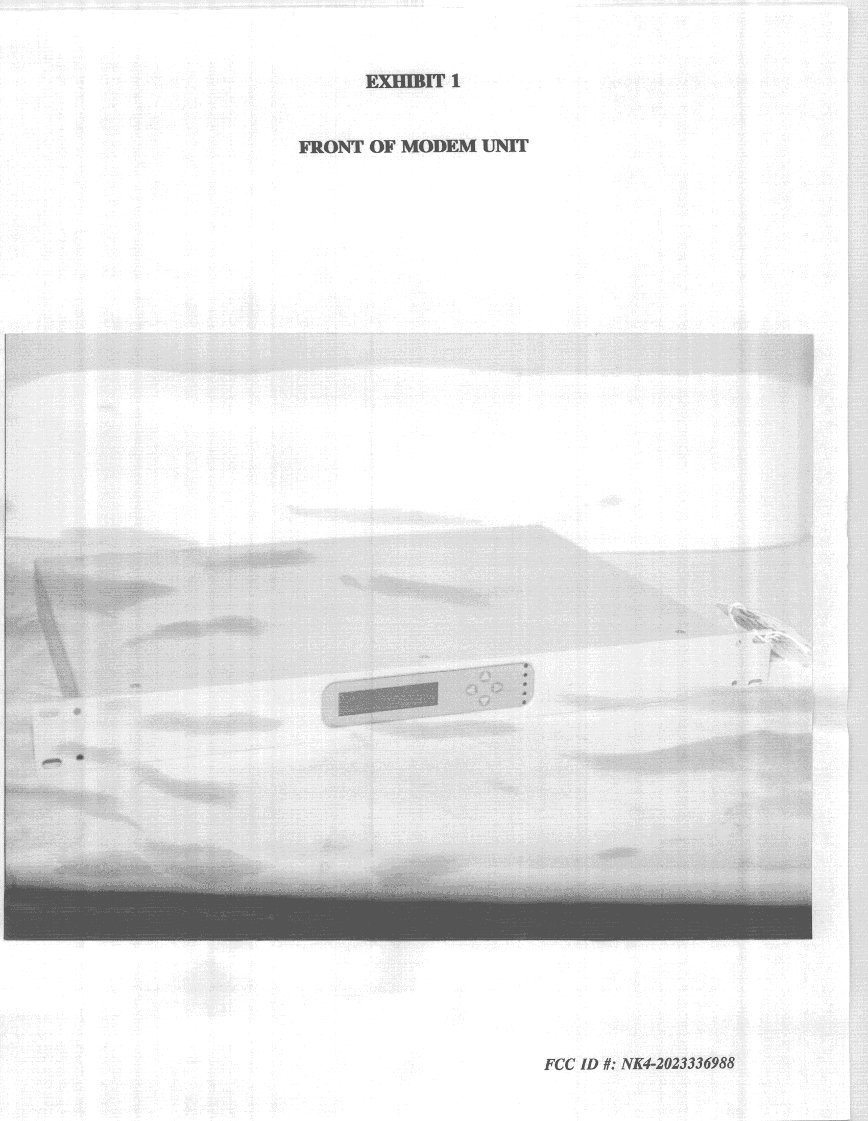
NK4-2023336988
Jan 14, 1999Data Transceiver
Equipment Class
DSS - Part 15 Spread Spectrum TransmitterNK4-202333WAVE
Sep 30, 1997Point-to-Point Communications Transmitter Maximum Output Power 50 mW This device must be professionally installed.
Equipment Class
DSS - Part 15 Spread Spectrum Transmitter