NKF-INDY2230Disk Array
Maxtronic International Co Ltd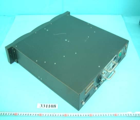
Click to zoom
Application Details
- Equipment Class
- JBP - Part 15 Class B Computing Device Peripheral
- Date of Grant
- May 08, 2003
- Application Purpose
- Original Equipment
- Date of Application
- May 08, 2003
- Equipment Note
- Disk Array
- Country
- Taiwan
Documents & Files
Document Text
Text extracted from the exhibit documents filed with the FCC. Open a document above to read the original.
Users Manual
Ultra 160 SCSI to IDE Disk Array system User’s Guide Version 1.0 Feb. 2003 P/N. G414236 Arena Indy 2230 Ultra 160 SCSI to IDE Disk Array system User’s Guide Version 1.0 Feb. 2003 P/N. G414236 ID-2230 2003 MaxTronic International Co., Ltd. All rights reserved. No part of this written material may be reproduced, stored in a retrieval system, used in any form or by any means, electronic or mechanical, photocopying, recording, or otherwise, without the written permission of MaxTronic International CO., LTD. Copyright Notice 1. Before starting, take a few minutes to read this manual, read all of these instructions and save this manual for later reference. 2. Protect the Disk Array from extremely high or low temperatures. Let the Disk Array warm (or cool ) to room temperature before using it. 3. Protect the Disk Array from being bumped or dropped. Do not place this product on an unstable cart, stand, or table. It may fall, causing serious damage to the product. 4. Keep the Disk Array away from magnetic forces. 5. Do not use this product near water. 6. Keep the Disk Array away from dust, sand, or dirt. 7. Gaps and openings in the cabinet and the back are provided for ventilation. To ensure reliable operation and to protect it from overheating, the gaps and openings should never be blocked or covered by placing the product on a bed, sofa, rug, or other similar surface. 8. Do not place this product near or over a radiator or heat register. 9. Refer to rating plate for voltage and check the appliance voltage corresponds to the supply voltage. 10. The appliance must be grounded. This product is equipped with a 3wire grounding-type power cord, this power cord will only fit into a groundingtype power outlet. Important! Safety Instructions, Care and Handling 11. If an extension cord or a power center is used with this product, make sure that the total of all products plug into the wall outlet does not exceed the ampere rating. 12. Do not place the Disk Array where the cord will be walked on. 13. Never push any kind of object into this product through cabinet gaps and openings, they may touch dangerous voltage points cause a risk of fire or electric shock. 14. Unplug the power cord from the wall outlet before cleaning. Keep the Disk Array dry. Do not use liquid cleaners, aerosol cleaners, or a wet cloth. Use a damp cloth for cleaning. 15. Except as specifically explained in this User’s Manual, please do not attempt to service this product by yourself. Opening or removing the covers may expose you to dangerous voltages. 16. Unplug this product from the wall outlet and refer servicing to qualified service personnel under the following conditions : zIf this product has been exposed to water or any liquid. zIf the product has been dropped or the cabinet damaged. When selecting a suitable working location, please consider : zVentilation zTemperature zDust and dirt zElectromagnetic and Radio Frequency Interference. zSecurity The selected location should provide at least six inches of open space around the Disk Array cabinet for proper air flow. Your Disk Array functions best at normal room temperature. Choose a location free from extreme heat or cold. Your Disk Array should be used in a clean environment that is free from airborne contaminants such as dust, dirt, and smoke. Excessive moisture or oil particles in the air can also hinder your system’s performance. To reduce the possibility of data errors caused by electromagnetic interference, locate your Disk Array at least five feet away from electrical appliances and equipment that generates magnetic fields. Operating Environment The Disk Array’s LCD Panel may be damaged by exposure to intense sunlight. Limit exposure to indirect or subdued sunlight only. Warning!! This manual serves as a useful guide you can refer to when you wish to install and operate your Disk Array. It includes the following information : z Chapter 1 : “ Introduction “ Introduces you to your new Disk Array’s features and general RAID concepts. z Chapter 2 : “ Getting Started “ Describes general information about this Disk Array. z Chapter 3 : “ Configuration “ Provides a Quick and Easy way to setup this Disk Array. z Chapter 4 : “ Advanced Information “ Describes information in more detail. z Chapter 5 : “ Hot-Swap “ Describes Hot-Swap components. z Appendix A : “ Technical Specification “ About This Manual Chapter 1 : Introduction Features.......................................................................... 1-2 General RAID concepts.....................................................1-4 RAID Level 0 .....................................................1-5 RAID Level 1 .....................................................1-6 RAID Level 3 .....................................................1-7 RAID Level 5 .....................................................1-8 Summary Comparison of RAID Levels............................... 1-10 Supported RAID Levels.....................................................1-11 Multi-SCSI Format support .....................................................1-12 Contents Chapter 2 : Getting Started General Overview ............................................................... 2-1 Unpacking & Checklist.................................................... 2-2 Choosing a place for Disk Array .......................................... 2-3 Identifying Parts of Disk Array Front View .....................................................2-4 Rear View .....................................................2-5 Power Source................................................................2-6 Installing the Hard Disk Drive.......................................... 2-7 How To Setup Active Terminator .......................................... 2-10 Host Linkage .......................................................................... 2-11 Power-On & Self-Test............................................................... 2-12 LED Display & Function Keys LED Display...…
Text truncated - open the document above for the full version.
Block Diagram
block diagram For both RAID FCC ID: NKF-INDY2230
External Photos
FCC ID : NKF-INDY2230 Number1 FRONT SIDE OF EUT FCC ID : NKF-INDY2230 Number2 REAR SIDE OF EUT
ID Label/Location Info
FCC ID : NKF-INDY2230 FCC ID LOCATION
Internal Photos
FCC ID: NKF-INDY2230 Number 1 Closer look of rear interface port FCC ID: NKF-INDY2230 Number 2 Mechanical construction FCC ID: NKF-INDY2230 Number 3 Mechanical construction FCC ID: NKF-INDY2230 Number 4 Mechanical construction FCC ID: NKF-INDY2230 Number 5 Mechanical construction FCC ID: NKF-INDY2230 Number 6 Mechanical construction FCC ID: NKF-INDY2230 Number 7 Mechanical construction FCC ID: NKF-INDY2230 Number 8 Mechanical construction FCC ID: NKF-INDY2230 Number 9 Mechanical construction 1 FCC ID: NKF-INDY2230 Number 10 Front side of controller FCC ID: NKF-INDY2230 Number 11 Rear side of controller FCC ID: NKF-INDY2230 Number 12 Front side of memory FCC ID: NKF-INDY2230 Number 13 Rear side of memory FCC ID: NKF-INDY2230 Number 14 Front side of daughter board FCC ID: NKF-INDY2230 Number 15 Rear side of daughter board FCC ID: NKF-INDY2230 Number 16 Front side of LCD module FCC ID: NKF-INDY2230 Number 17 Rear side of LCD module FCC ID: NKF-INDY2230 Number 18 Front side of module board FCC ID: NKF-INDY2230 Number 19 Rear side of module board FCC ID: NKF-INDY2230 Number 20 Front side of main board of power module FCC ID: NKF-INDY2230 Number 21 Rear side of main board of power module FCC ID: NKF-INDY2230 Number 22 Front side of power main board FCC ID: NKF-INDY2230 Number 23 Rear side of power main board FCC ID: NKF-INDY2230 Number 24 Front side of module board FCC ID: NKF-INDY2230 Number 25 Rear side of module board FCC ID: NKF-INDY2230 Number 26 HDDs and HDD cases FCC ID: NKF-INDY2230 Number 27 Front side of HDD FCC ID: NKF-INDY2230 Number 28 Rear side of HDD FCC ID: NKF-INDY2230 Number 29 Mechanical construction of HDD case FCC ID: NKF-INDY2230 Number 30 Front side of power FCC ID: NKF-INDY2230 Number 31 Rear side of power FCC ID: NKF-INDY2230 Number 32 Front side of power FCC ID: NKF-INDY2230 Number 33 Front side of power module FCC ID: NKF-INDY2230 Number 34 Rear side of power module FCC ID: NKF-INDY2230 Number 35 Front side of power module FCC ID: NKF-INDY2230 Number 36 SCSI & RS232 cable 2
Test Report
FCC TEST REPORT Report No. : F331108 SPORTON International Inc. TEL : 886-2-2696-2468 FAX : 886-2-2696-2255 FCC TEST REPORT for 47 CFR, Part 2, Part 15 Subpart B and CISPR PUB. 22 Equipment : Disk Array Model No. : INDY 2230 FCC ID : NKF-INDY2230 Filing Type : Certification Applicant : MaxTronic International Co., Ltd. 4F, No. 529, Chung Cheng Rd., Hsin Tien City, Taipei Hsien, Taiwan, R.O.C. The test result refers exclusively to the test presented test model / sample. Without written approval of SPORTON International Inc., the test report shall not be reproduced except in full. Certificate or Test Report must not be used by the applicant to claim the product in this test report endorsement by NVLAP or any agency of U.S. government. SPORTON International Inc. 6F, No.106, Sec. 1, Hsin Tai Wu Rd., Hsi Chih, Taipei Hsien, Taiwan, R.O.C. FCC TEST REPORT Report No. : F331108 SPORTON International Inc. FCC ID : NKF-INDY2230 TEL : 886-2-2696-2468 Page No. : i FAX : 886-2-2696-2255 Issued Date : Mar. 27, 2003 Table of Contents History of this test report..................................................................................................................ii CERTIFICATE OF COMPLIANCE........................................................................................................................1 1. General Description of Equipment under Test.............................................................................................2 1.1 Applicant..........................................................................................................................................................................................2 1.2 Manufacturer ...................................................................................................................................................................................2 1.3 Basic Description of Equipment under Test ....................................................................................................................................2 1.4 Feature of Equipment under Test ...................................................................................................................................................3 2. Test Configuration of Equipment under Test ...............................................................................................4 2.1 Test Manner ....................................................................................................................................................................................4 2.2 Description of Test System .............................................................................................................................................................5 2.3 Connection Diagram of Test System ..............................................................................................................................................7 3. Test Software ...................................................................................................................................................8 4. General Information of Test............................................................................................................................9 4.1 Test Facility .....................................................................................................................................................................................9 4.2 Test Voltage ....................................................................................................................................................................................9 4.3 Standard for Methods of Measurement...........................................................................................................................................9 4.4 Test in Compliance with ..................................................................................................................................................................9 4.5 Frequency Range Investigated .......................................................................................................................................................9 4.6 Test Distance ..................................................................................................................................................................................9 5. Test of Conducted Powerline .......................................................................................................................10 5.1 Major Measuring Instruments........................................................................................................................................................10 5.2 Test Procedures ............................................................................................................................................................................11 5.3 Typical Test Setup Layout of Conducted Powerline .....................................................................................................................12 5.4 Test Result of AC Powerline Conducted Emission .......................................................................................................................13 6. Test of Radiated Emission............................................................................................................................15 6.1 Major Measuring Instruments........................................................................................................................................................15 6.2 Test Procedures ............................................................................................................................................................................16 6.3 Typical Test Setup Layout of Radiated Emission..........................................................................................................…
Text truncated - open the document above for the full version.
Test Setup Photos
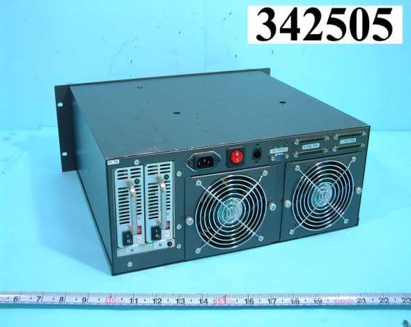
FCC TEST REPORT Report No. : F331108 SPORTON International Inc. FCC ID : NKF-INDY2230 TEL : 886-2-2696-2468 Page No. : 1 of 3 FAX : 886-2-2696-2255 Issued Date : Mar. 27, 2003 1.1. Photographs of Conducted Emission Test Configuration The photographs show the configuration that generates the maximum emission. FRONT VIEW REAR VIEW FCC TEST REPORT Report No. : F331108 SPORTON International Inc. FCC ID : NKF-INDY2230 TEL : 886-2-2696-2468 Page No. : 2 of 3 FAX : 886-2-2696-2255 Issued Date : Mar. 27, 2003 SIDE VIEW FCC TEST REPORT Report No. : F331108 SPORTON International Inc. FCC ID : NKF-INDY2230 TEL : 886-2-2696-2468 Page No. : 3 of 3 FAX : 886-2-2696-2255 Issued Date : Mar. 27, 2003 1.2. Photographs of Radiated Emission Test Configuration The photographs show the configuration that generates the maximum emission. FRONT VIEW REAR VIEW
Contact Information
Applicant
Y. M. Chang(Managing Director)
886 2 2218-4875Fax: 886 2 2218-4896
Test Firm
SPORTON International IncKathy Lin
Technical Specifications
| # | Rule Parts | Frequency Range | Power Output |
|---|---|---|---|
| 1 | 15B | - | - |
Other Applications from Maxtronic International Co Ltd
NKF-RACKFORCEII
Aug 03, 2003Disk Array
Equipment Class
JBP - Part 15 Class B Computing Device Peripheral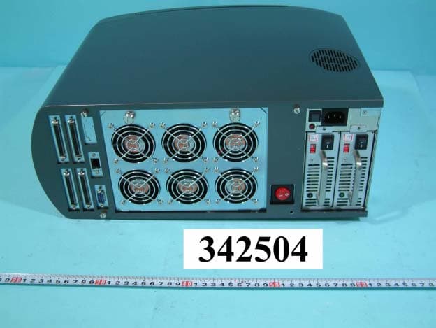
NKF-DESKFORCEII
Jul 28, 2003DISK ARRAY
Equipment Class
JBP - Part 15 Class B Computing Device Peripheral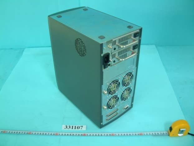
NKF-ARENAEXIII
May 08, 2003Disk Array
Equipment Class
JBP - Part 15 Class B Computing Device Peripheral
NKF-FIDY
Jul 01, 2002Disk Array
Equipment Class
JBP - Part 15 Class B Computing Device Peripheral
NKF-INDY-2400
Jun 25, 2002Disk Array
Equipment Class
JBP - Part 15 Class B Computing Device Peripheral