NKM313Human Fall Sensor TX
iLife Systems Inc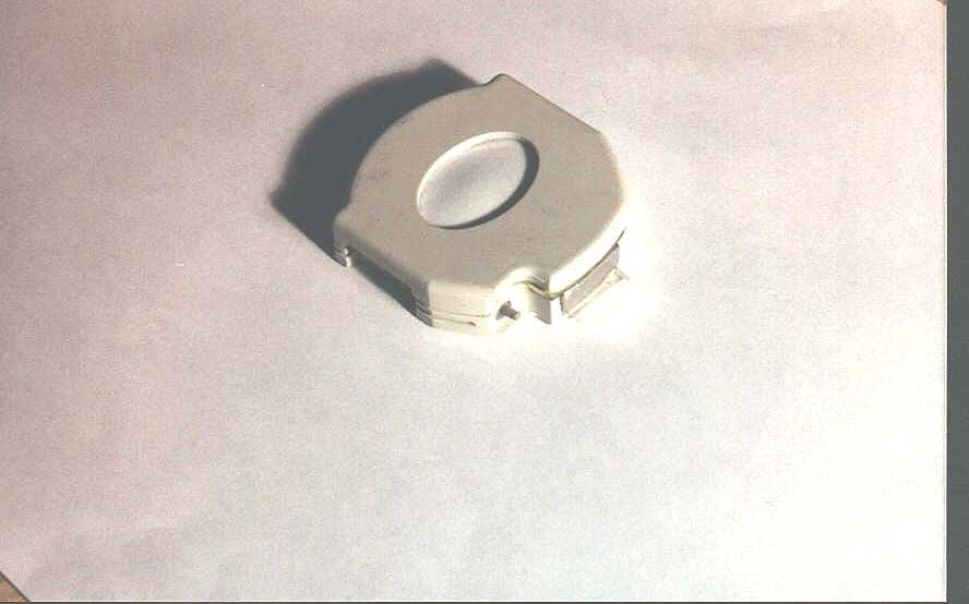
Click to zoom
Application Details
- Equipment Class
- DSC - Part 15 Security/Remote Control Transmitter
- Date of Grant
- Feb 09, 2000
- Application Purpose
- Original Equipment
- Date of Application
- Dec 08, 1999
- Equipment Note
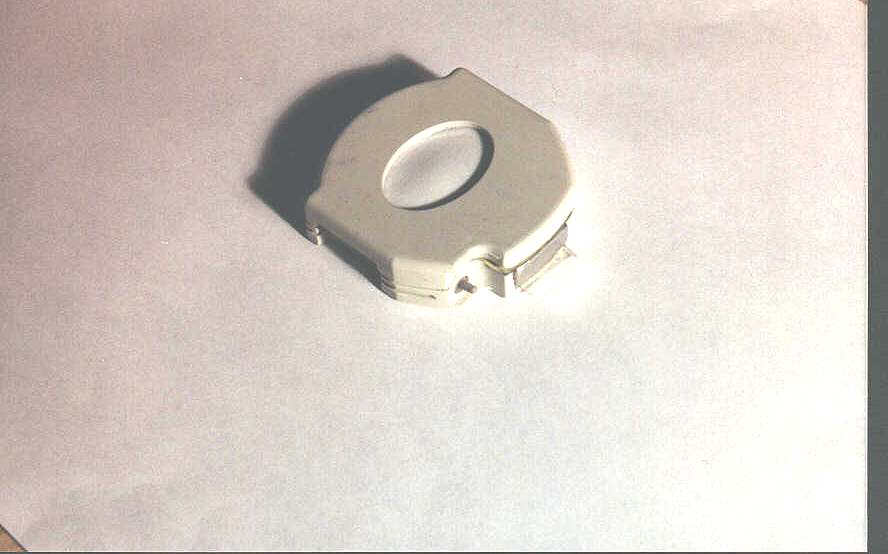
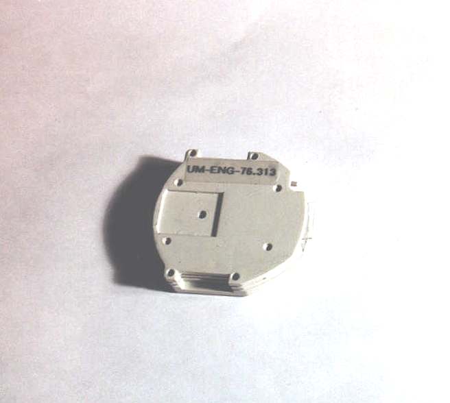
- Human Fall Sensor TX
- Frequency Range
- 313.52000000 - 313.52000000
- Company
- iLife Systems Inc
- Country
- United States
Documents & Files
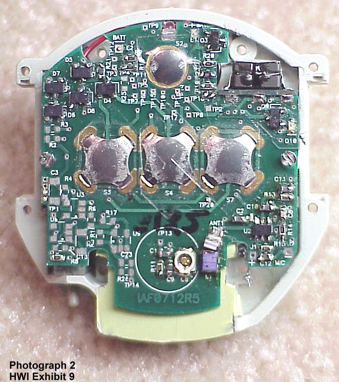
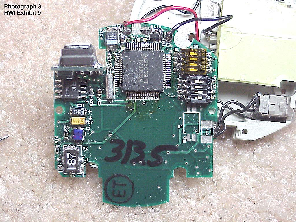
Document Text
Text extracted from the exhibit documents filed with the FCC. Open a document above to read the original.
Users Manual
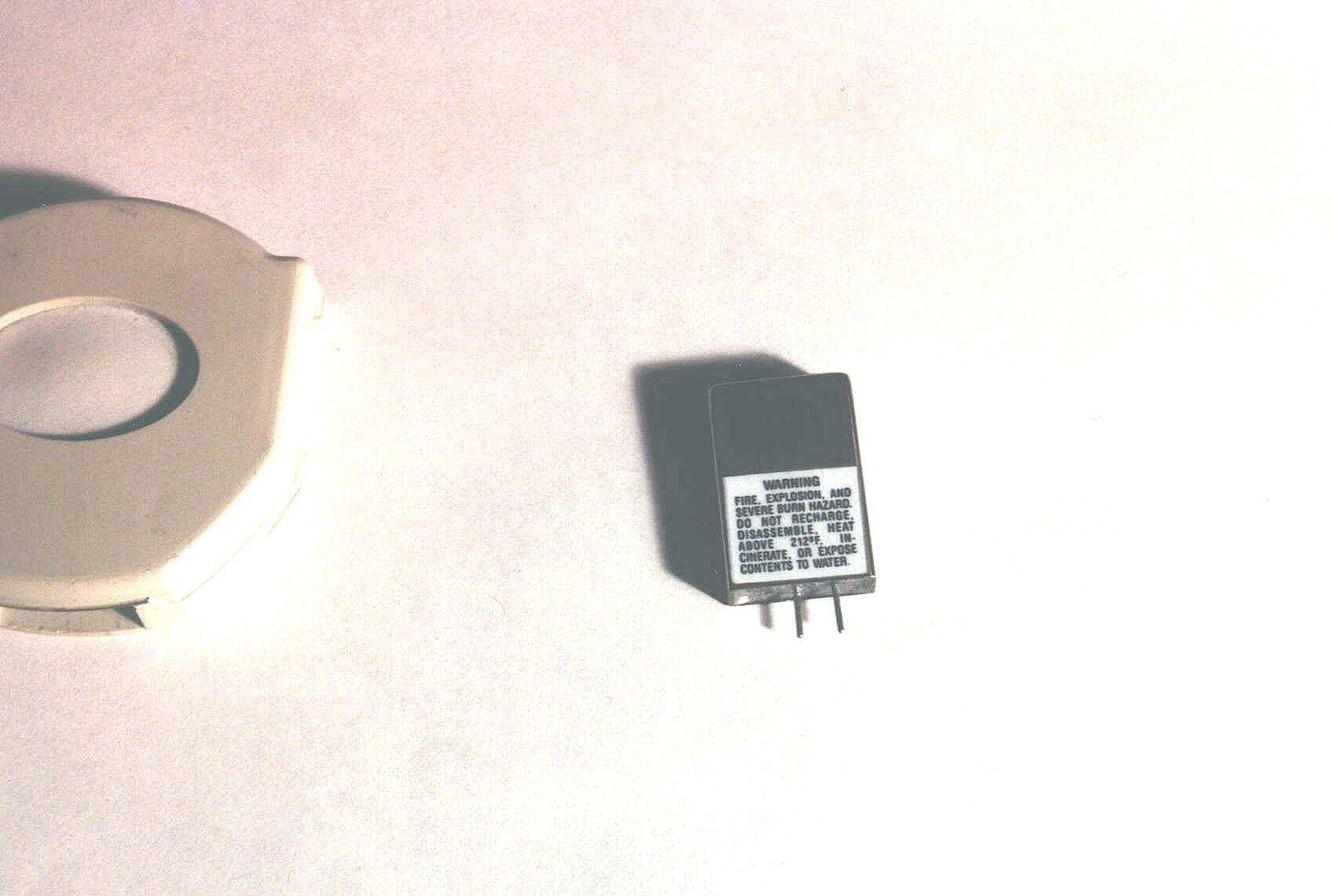
iLife Technologies E:\IAMFINE\Fall Alert 313\Fall Alert 313 General Operating Manual.doc 11/17/99 2:33 PM Page 1 of 5 Fall Alert 313 GENERAL OPERATING MANUAL---DRAFT General Product Description Intended Use of Fall Alert 313 Fall Alert 313 is a security system that senses position and monitors falls. Fall Alert 313 is worn by a person considered to be at risk of falling. The system is easy to use, and generates few false alarms. The system originates alarms locally through a Fall Alert 313 Wall Receiver and then into an existing Emergency Response Center (ERC). Emergency Response Center The Fall Alert 313 system alerts an ERC if the user falls or needs assistance. The system allows two- way voice communication so that the Emergency Response Operator may speak directly with the individual to determine what events have occurred and what actions should be taken. The professionals at the center will then call the caregiver or another designated responder to provide immediate assistance if help is needed. The ERC monitors twenty-four hours a day, seven days a week. Once the remote wall receiver is connected to a working AC power outlet and a telephone line, and there is a fresh battery in the Fall Alert 313 User Module, the system is ready to automatically dial the Emergency Response Center. Once the user module is activated, the signal is sent to the wall receiver and through dial-up phone lines to alert the ERC. The ERC is equipped with computers that hold vital information regarding the user’s household. This information includes addresses and phone numbers of the user and designated responders, and any special medical information about the user. The Emergency Response Operator then uses this information to alert the proper individual(s) of the wearer’s needs. All the while, the Operator is able to communicate with the user through the two-way speaker located in the wall receiver. If the user cannot be contacted, or cannot speak, emergency help will automatically be sent. Fall Detection iLife Technologies E:\IAMFINE\Fall Alert 313\Fall Alert 313 General Operating Manual.doc 11/17/99 2:33 PM Page 2 of 5 The user module is a miniature, self contained, battery operated, electronic fall alert system that uses a combination of referenced tilt angles and G force data that exceed fixed limits, for informing monitoring personnel at a remote location when a monitored person falls. Care and Maintenance The user module does not require any routine cleaning. However, should it become soiled, simply wipe with a wet cloth. Changing Batteries The user module contains one lithium battery. This battery should be changed every thirty (30) days to ensure proper operation. Precautions This section identifies some tips to ensure the proper operation of the personal help pendant. The user module should be worn somewhere below the shoulders and above the hips for the most accurate and effective placement. Please be sure to thoroughly test the range of the user module prior to use. The Fall Alert 313 unit emergency signal can be detected from as far away as 100 feet depending on the construction, furnishings, and other environmental factors within the home. DO NOT submerse any parts of this system in water. iLife Technologies E:\IAMFINE\Fall Alert 313\Fall Alert 313 General Operating Manual.doc 11/17/99 2:33 PM Page 3 of 5 Attachment Methods Fall Alert 313 Belt-Clip Attachment Pepe D:\BrettS\Projects\PERS\ Patient Modual\BeltClip Attachment.doc Belt Open Spring Remove with screwdriver Belt Clip iLife Technologies E:\IAMFINE\Fall Alert 313\Fall Alert 313 General Operating Manual.doc 11/17/99 2:33 PM Page 4 of 5 Fall Alert 313 Velcro Strap Attachment Pepe D:\BrettS\Projects\PERS\Patient Modual\VelcroStrap Attachment.doc Velcro Hook Velcro Loop Belt iLife Technologies E:\IAMFINE\Fall Alert 313\Fall Alert 313 General Operating Manual.doc 11/17/99 2:33 PM Page 5 of 5 FCC Emissions Compliance NOTE: This equipment has been tested and found to comply with the limits for a Class B digital device, pursuant to Part 15 of the FCC Rules. These limits are designed to provide reasonable protection against harmful interference in a residential installation. This equipment generates, uses and can radiate radio frequency energy and, if not installed and used in accordance with the instructions, may cause harmful interference to radio communications. However, there is no guarantee that interference will not occur in a particular installation. If this equipment does cause harmful interference to radio or television reception, which can be determined by turning the equipment off and on, the user is encouraged to try to correct the interference by one or more of the following measures: • Reorient or relocate the receiving antenna. • Increase the separation between the equipment and receiver. • Connect the equipment into an outlet on a circuit different from that to which the receiver is connected. • Consult the dealer or an experienced radio/TV technician for help. CAUTION: Changes or modifications not expressly approved or authorized by the manufacturer may violate the compliance of this equipment to the Class B limits for a digital device and could, thereby, void the users authority to operate the equipment
Test Report
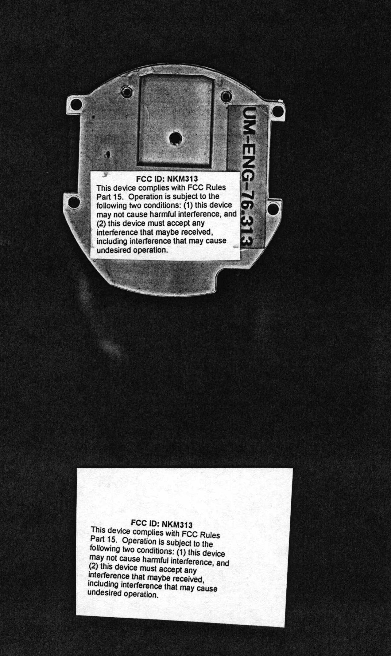
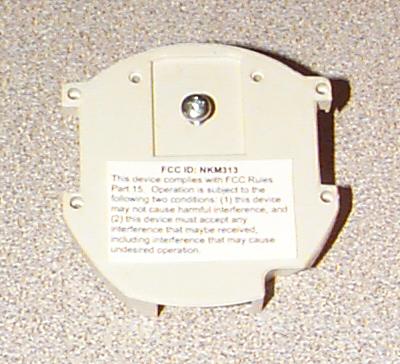
FCC ID: NKM313 1 RF ENERGY EMISSION TEST REPORT OF THE Caring Technologies Inc. Fall Alert 313 PREPARED BY: Markian Lapchak Mark Lapchak & Associates Inc. 6721 S. Leyden Ct. Englewood, Co. 80112 NARTE CERTIFICATION: EMC 001676 PREPARED FOR: Caring technologies Inc. 5910 N. Central Expressway Suite 1775 Dallas, Texas75206 214-365-7400 12/9/99 HWI1ex6 FCC ID: NKM313 2 TABLE OF CONTENTS SUMMARY 1.0 SCOPE AND OBJECTIVE OF TEST 2.0 UNIT TO BE TESTED 3.0 FACILITY REQUIREMENTS 3.1 SITE ATTENUATION 3.2 INSTRUMENTATION 4.0 SPURIOUS RADIATED EMISSIONS TEST 4.1 PROCEDURE 4.2 RESULTS 5.0 INTENTIONAL EMISSIONS AND OCCUPIED BANDWIDTH 5.1 PROCEDURE 5.2 RESULTS APPENDICES APPENDIX I TABLES1-6 GRAPHS1-2 TABLE OF OSCILLATOR FREQUENCIES TEST SYSTEM BLOCK DIAGRAM APPENDIX II TABLE OF CORRECTION FACTORS APPENDIX III FIGURES1-2 FCC ID: NKM313 3 SUMMARY The testing was performed under the provisions of ANSI C63.4/1992 and the OATS was calibrated in accordance with ANSI C63.4/1992. The Fall Alert 313, is hereafter referred to as the UUT. The UUT, with test setup as described in the block diagram of Appendix II,PASSESall the radiated requirements of the FCC Part 15, Subpart C regulations for a low power transmitter operating at 313.52 MHz pursuant to Section 15.231 of the Rules. Conducted Emissions are not required since this unit runs only on batteries which cannot be re-charged while inserted into the unit. The maximum field strength of the fundamental, measured with an "average" detector, was 56 dbμv/m versus a specification of 75.5 db. With the "peak" detector selected. the maximum field strength of the fundamental was 79 dbμv/m versus a specification of 95.5 db. The bandwidth of the intentional emission was .012% versus a specification of .25%. The spurious radiated emissions which came closest to the limit are as follows, rounded to the nearest db: FREQUENCY (MHz) EMISSION LEVEL (dbμv/meter) Polarization MARGIN(db) TABLES Appendix I 940.54 32 Horizontal -23.5 1 1254.1 49 Horizontal -24.5 1 1567.05 43 Vertical -4.5 2 1881 40 Vertical -13.5 2 For more details, see Appendix I, Tables1-6andGRAPHS1-2. A negative margin means that the emissions are under the specified limit by the indicated amount. The antenna is internal to the unit and not accessible to the user and meets the requirements of 15.203 of the Rules. FCC ID: NKM313 4 SUMMARY (cont) INFORMATION SUPPLIED TO THE USER The manual contains a cautionary statement required by Section 15.21 of the FCC rules for an intentional radiator." CAUTION: Changes or modifications not expressly approved or authorized by the manufacturer may violate the compliance of this equipment to the Class B limits for a digital device and could, thereby, void the users authority to operate the equipment. The label on the outside of the equipment enclosure contains the FCC ID and the following text: FCC ID:NKM313 This device complies with Part 15 of the FCC Rules. Operation is subject to the following two conditions: (1) this device may not cause harmful interference, and (2) This device must accept any interference received, including interference that may cause undesired operation. Caring Technologies shall maintain records listed in Section 2.938 of the FCC rules. FCC ID: NKM313 5 1.0 SCOPE AND OBJECTIVE OF TEST To determine the degree of compliance of products to the Federal Communications Commission Part 15 Subpart C requirements for intentional radiators which limit emissions of Low Power Transmitter Devices pursuant to pp 15.231 through the certification process. 2.0 UNIT TESTED The Fall Alert Security System, manufactured by Caring Technologies Inc, 5910 N Central Expressway, Dallas, Texas 75206, hereafter referred to as the UUT, is intended to be worn by persons at risk of falling. If a fall or other alarm condition is detected, the unit transmits an alarm signal to a wall receiver and then into an existing Emergency Response Center. 3.0 FACILITY REQUIREMENTS 3.1 Site Attenuation The radiated testing described herein was accomplished on the METRUM OATS which is located at 4800 E. Dry Creek Road, Littleton, CO 80122. This site meets the requirements of FCC 47 CFR rules, Section 2.948. Refer to FCC File # 31040/SIT/1300F2 for a detailed description of the site. The test area is free of reflecting objects in an area as defined in Figure 1, Appendix III. 3.2 Instrumentation Polarad ESV Receiver, #6003594, calibrated 2/10/99, calibration due 2/10/2000 Polarad ESH2 Receiver, #6003696, calibrated 3/8/99, calibration due 3/8/2000. Rhode & Schwarz HFH2-Z2 Magnetic Field Active Loop Antenna, 10 KHz - 30 MHz. HP 8565A Spectrum Analyzer, s/n 2210A02349, 100 MHz - 18 GHz, Calibrated 9/27/99, Calibration Due 3/27/2000. Ailtech 94455-1 Biconical Antenna, 30 -200 MHz, Cal'd 8/3/99, Cal Due 8/3/2000. Ailtech 96005 Log Periodic Antenna, 200 MHz - 1 GHz, Cal'd 8/3/99, Cal Due 8/3/2000. AH Systems Horn Antenna, model SAS-200/571, s/n 339, 1-18 GHz, Calibrated 4/14/99, No re-calibration required. Avantek UTC 10-220-1 25 db Preamp, #211.093, Calibrated 3/8/99, calibration due 3/8/2000. JCA Technology JCA 15-416, 40 db preamp, # 6010088, 1-5 GHz, Calibrated 9/3/99, Calibration Due 9/3/2000. FCC ID: NKM313 6 4.0 SPURIOUS RADIATED TEST PROCEDURE AND RESULTS 4.1 Procedure 4.1.1 Setup of equipment on the test site, for detailed measurements, was according to Figure 2, Appendix III and the block diagram of Appendix II.The ANSI C63.4/1992 measurement procedure was followed. 4.1.2 The UUT was placed in a special test mode which caused it to transmit continuously for ease of making the measurements. In reality the transmission would occur infrequently. During the transmissions, there are bursts of data lasting 12.5 msec, spaced about 125 msec apart which automatically stop after 3 seconds. This results in a 10% duty cycle. See Figures3&4of Appendix III. Over 100 msec, this produces an "average factor of 18 db. (See 4.1.9) Initially, two conditions were tested: 4.1.2.1 UUT Flat on its back, top at 0 ° w…
Text truncated - open the document above for the full version.
Test Setup Photos
HWI Fall Alert 313 Exhibit 7 Photo Index EMI TEST SETUP Photograph 1: Overall Front View, Vertical Polarization, 30 MHz - 200 MHz Scan Photograph 2: Overall Rear View, Vertical Polarization, 30 MHz - 200 MHz Scan Photograph 3: Overall Rear View, Horizontal Polarization, 30 MHz - 200 MHz Scan Photograph 4: Overall Rear View, Horizontal Polarization, 200 MHz - 1 GHz Scan Photograph 5: Overall Rear View, Vertical Polarization, 200 MHz - 1 GHz Scan Photograph 6: Overall Rear View, Vertical Polarization, 1 GHz - 3.13 GHz Scan Photograph 7: Overall Rear View, Horizontal Polarization, 1 GHz - 3.13 GHz Scan
Test Setup Photos
HWI Fall Alert 313 Exhibit 7 Photo Index EMI TEST SETUP Photograph 1: Overall Front View, Vertical Polarization, 30 MHz - 200 MHz Scan Photograph 2: Overall Rear View, Vertical Polarization, 30 MHz - 200 MHz Scan Photograph 3: Overall Rear View, Horizontal Polarization, 30 MHz - 200 MHz Scan Photograph 4: Overall Rear View, Horizontal Polarization, 200 MHz - 1 GHz Scan Photograph 5: Overall Rear View, Vertical Polarization, 200 MHz - 1 GHz Scan Photograph 6: Overall Rear View, Vertical Polarization, 1 GHz - 3.13 GHz Scan Photograph 7: Overall Rear View, Horizontal Polarization, 1 GHz - 3.13 GHz Scan
Contact Information
Applicant
Joshua Adler
Test Firm
Sypris Test and MeasurementMarkian Lapchak
Technical Specifications
| # | Rule Parts | Frequency Range | Power Output |
|---|---|---|---|
| 1 | 15C | 313.52 MHz - 313.52 MHz | - |
Other Applications from iLife Systems Inc
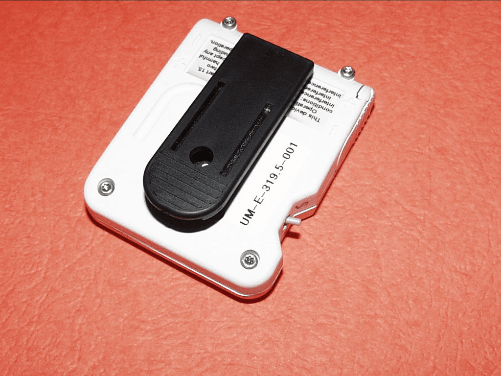
NKM319
Jan 01, 2001HealthSensor 100
Equipment Class
DXX - Part 15 Low Power Communication Device TransmitterNKM-IAF100
Oct 01, 1997Medical Telemetry Transmitter
Equipment Class
DXX - Part 15 Low Power Communication Device Transmitter