NKM319HealthSensor 100
iLife Systems Inc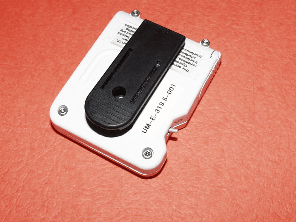
Click to zoom
Application Details
- Equipment Class
- DXX - Part 15 Low Power Communication Device Transmitter
- Date of Grant
- Jan 01, 2001
- Application Purpose
- Original Equipment
- Date of Application
- Jan 01, 2001
- Equipment Note
- HealthSensor 100
- Frequency Range
- 319.51000000 - 319.51000000
- Company
- iLife Systems Inc
- Country
- United States
Documents & Files
Document Text
Text extracted from the exhibit documents filed with the FCC. Open a document above to read the original.
Users Manual
W:\TCB FILINGS\HWI\user manual\healthsensor 100 users guide.doc 1 of 11 iLife Systems HealthSensor 100 Fall Detection and Help Button User's Guide W:\TCB FILINGS\HWI\user manual\healthsensor 100 users guide.doc 2 of 11 HealthSensor 100 Fall Detection and Personal Help Button Calls for Help Even When You Cannot The HealthSensor 100 Fall Detection and Personal Help Button provides you with assistance that no other personal help button product can offer. Your HealthSensor pendant will alert your emergency monitoring service automatically when it detects a fall, even if you are unable to push the help button on the pendant. The HealthSensor pendant provides you with a help button but contains the added safety of automatically calling for help when it detects the conditions of a fall. This unique added protection is only available with the HealthSensor 100 Fall Detection and Personal Help Button pendant. The HealthSensor 100 Fall Detection and Personal Help Button Pendant is designed to work in and immediately around your home. The pendant must be close enough to the receiver for a help signal to be transmitted. The coverage area for the pendant will vary from one home to another. It is important for you to know the effective range of your pendant. The HealthSensor 100 Fall Detection is designed to detect falls that meet certain criteria. It may not detect every fall, especially slight falls that are generally not disabling. The HealthSensor 100 Fall Detection device may also generate a fall alarm when you have not fallen. For example, dropping the pendant on the floor may cause the device to send an alert to the monitoring center that you have fallen. W:\TCB FILINGS\HWI\user manual\healthsensor 100 users guide.doc 3 of 11 How to Wear the HealthSensor 100 The HealthSensor Fall Detection pendant is designed to automatically sense the conditions of a fall and send an emergency alert when a fall occurs. To send an alarm that you have fallen the pendant must be worn by you. The Fall Detection pendant must be worn on your torso in an upright manner. Wearing the pendant on your arm or leg may cause the device to false alarm or to fail to alarm upon a real fall. Wearing the pendant so that it is not right side up may cause the device to not function properly. Some typical wearing suggestions are as follows: On your waist The HealthSensor can be worn on your waist either attached to your belt or the waist of your pants. The HealthSensor pendant comes with a belt clip that is specifically designed to be easy to attach to a belt. CorrectIncorrect W:\TCB FILINGS\HWI\user manual\healthsensor 100 users guide.doc 4 of 11 The pendant can be attached by holding the clip and putting it on (figure 1) or by rotating the pendant on and off of the belt (figure 2). Remember to have the picture show the proper final position of the device - upright on the belt. Rotate into Place W:\TCB FILINGS\HWI\user manual\healthsensor 100 users guide.doc 5 of 11 In a shirt pocket The HealthSensor pendant can be worn clipped to a shirt pocket. It generally works best with the pendant resting on the inside of the pocket. Fabrifoam Belt The pendant can be attached to a fabrifoam belt accessory that is worn on the inside or outside of your clothing. This belt is purchased separately. Brassiere/Garment Clip A factory installed, optional brassiere/garment clip can be attached to the front of the HealthSensor unit and the belt clip may be removed. You may use the brassiere/garment clip to attach the unit to a brassiere. The unit may also be clipped to the fabrifoam belt with a smaller profile than the belt clip. Battery Life of the HealthSensor 100 pendant The battery life of the HealthSensor pendant is approximately forty-five to sixty days. The HealthSensor pendant is always on and alert while you are wearing it - the Fall Detection sensor is constantly monitoring your position to determine if a fall has occurred. Pocket W:\TCB FILINGS\HWI\user manual\healthsensor 100 users guide.doc 6 of 11 Low Battery Warnings When the HealthSensor pendant senses that the triple A batteries inside the unit are low, the LED on the top of the unit will begin to blink about once per second until the battery is completely out of power. The pendant will also send three low battery warnings to the base station in your home. The first low battery warning is sent when there is about four days of battery life left in the unit. The second warning comes when there is about two days and the final warning is sent when there is one day or less of battery life left in the pendant. CAUTION: If the HealthSensor pendant is not in range of the base station when the battery is low, the base station will not receive the low battery signal and will not be able to alert the monitoring center. The base station will send a silent alarm to the monitoring center when a low battery condition is received from the pendant. The monitoring center will then call you at a convenient time to remind you to change the batteries in the pendant. Installing the HealthSensor 100 Pendant Batteries The HealthSensor pendant takes two triple A alkaline batteries. CAUTION: Only use fresh batteries of the required size and recommended type and follow all instructions to install them properly. Blinking means Low Battery W:\TCB FILINGS\HWI\user manual\healthsensor 100 users guide.doc 7 of 11 Follow these instructions to install the batteries: 1. Open the battery door in the direction of the arrow to remove it. Remove the existing batteries from the pendant. 2. Install the batteries in the direction indicated on the back of the cabinet Close the battery door on the pendant. 3. The LED light on the front of the unit will stay on for about ten seconds after the batteries have been installed to indicate the pendant has power. + + W:\TCB FILINGS\HWI\user manual\healthsensor 100 users guide.doc 8 of 11 4. Test the operation of the device by pushing the help button. This should alert the monitoring cen…
Text truncated - open the document above for the full version.
Attestation Statements
ATTESTATION STATEMENT SUMMARY: All tests according to CFR 47 Part 15, Paragraphs 15.209 and 15.231 were n- Performed The Equipment Under Test n - Fulfills the requirements of CFR 47 Part 15, Paragraphs 15.209 and 15.231. Equipment Received Date:06 November 2000 _______________________ Testing Start Date:06 November 2000 _______________________ Testing End Date:06 November 2000 _______________________ - TÜV PRODUCT SERVICE, INC. - Reviewed By:Tested By: Robert CresswellCarlos Marrero
Block Diagram
BLOCK DIAGRAM of the HEALTH SENSOR 100 Internal wire antenna RF @319.5 Enable From u ProcessorDigital Modulation Data Packet 5th OT Colpitts Osc. 106.5MHz Fixed tuned to 3rd harmonic (319.5MHz) Matching network Transistor Amp. AM Modulated 3.3 VDC Matching network
ID Label/Location Info
C:\standard\coreltitle.cdr IPERS AAA FCC label for 319.5 Mhz B 1OF1 FCC label AAA Cabinet 319.cdr BDS 11/2/00 1:1 Notes: 1) Rounded corners (.06“R). 2) to go under polyurethane cover 3) PMS 424 (Dark Gray) text on clear background 4) material: .002“ clear polyester with .001” clear matte lamination. 5) Adhesive: Permanent, to be mounted on ABS/PC. 6)Backer material to be .10“ (each side) or larger than label; strip format. Matrix removed from liner. Arial Font 4.5 point Labels shown in the installed position With Belt Clip Shown With Belt Clip NOT Shown Labels shown in the installed position F C C I D : N K M 3 1 9 T h i s d e v i c e c o m p l i e s w i t h F C C R u l e s . O p e r a t i o n i s s u b j e c t t o t h e f o l l o w i n g t w o c o n d i t i o n s : ( 1 ) t h i s d e v i c e m a y n o t c a u s e h a r m f u l i n t e r f e r e n c e , a n d ( 2 ) t h i s d e v i c e m u s t a c c e p t a n y i n t e r f e r e n c e r e c e i v e d , i n c l u d i n g i n t e r f e r e n c e t h a t m a y c a u s e u n d e s i r e d o p e r a t i o n . P a r t 1 5 o f FCC ID: NKM319 This device complies with FCC Rules. Operation is subject to the following two conditions: (1) this device may not cause harmful interference, and (2) this device must accept any interference received, including interference that may cause undesired operation. Part 15 of the 1.500" UM-XXX-XXXX 0 . 5 0 0 " IAF0814 1-LAB-0010 .015 .010 .005 1 DEG A E C O I A F 1 4 5 1 1 / 7 / 0 0 F C C I D : N K M 3 1 9 T h i s d e v i c e c o m p l i e s w i t h P a r t 1 5 F C C R u l e s . O p e r a t i o n i s s u b j e c t t o t h e f o l l o w i n g t w o c o n d i t i o n s : ( 1 ) t h i s d e v i c e m a y n o t c a u s e h a r m f u l i n t e r f e r e n c e , a n d ( 2 ) t h i s d e v i c e m u s t a c c e p t a n y i n t e r f e r e n c e r e c e i v e d , i n c l u d i n g i n t e r f e r e n c e t h a t m a y c a u s e u n d e s i r e d o p e r a t i o n .
Operational Description
W:\TCB FILINGS\HWI\operating_description\health sensor 100 theory of operation.doc Health Sensor 100 Theory of Operation Don James November 3, 2000 This product is powered by two AAA batteries and is designed to detect an actual “fall down” event that might be encountered by older persons that might be inclined to fall. The usage environment could include established health care facilities and institutions as well as in-home use. The included transmitter will communicate with a nearby receiver to notify a caregiver that a “fall” event has occurred. The main oscillator is a crystal controlled 5 th overtone operating at 106.5MHz. The 3 rd harmonic is selected in a matching network and is buffered by a one transistor stage buffter amplifier prevent antenna loading effects that otherwise might effect the RF frequency or amplitude. The RF transmission occurs in response to a burst of pulses from a microprocessor. Each burst consists of one wide pulse followed by an ID code (see the oscilloscope printouts for detailed timing). Each pulse packet is used to AM (on/off) modulate the output amplifier stage operating at 319.5MHz. A tuned circuit in the output stage maximizes the 319.5MHz RF output frequency and attenuates the harmonics. A pi network in series with the antenna provides additional matching and increased attenuation at the higher harmonics. The antenna is a short length of wire on top of the PC board mounted components. The transmission of data packets is automatically terminated in less than 5 seconds.
Parts List/Tune Up Info
Document Number Attachment 7 Cal Procedure12-21-00 1 CAL PROCEDURE FOR: EPC0902ME REV E TABLE OF CONTENTS Special Instructions ...................................................................................2 Test Procedure .........................................................................................3 Frequency Tuning Chart ..............................................................................7 BOM (Grouped) ........................................................................................8 BOM (Sorted) ..........................................................................................10 Original Release 6-24-99 Revised 12-21-00 Revised test procedure. Document Number Attachment 7 Cal Procedure12-21-00 2 TEST PROCEDURE FOR REV E EVISCERATOR SPECIAL INSTRUCTIONS: For 6 volt units change U2 form EIC7805MS to EIC1129RS Document Number Attachment 7 Cal Procedure12-21-00 3 WARNING! To prevent ESD, always wear ground straps when handling radios. SCOPE: This document describes the procedure to be used for the electrical test of Terminator (board number EPC0902ME) modems. PROCEDURE: EQUIPMENT SETUP 1. Turn on the power supply and set it to 9.5 volts. 2. Turn on the oscilloscope, press <SETUP>, and twist the unmarked knob until the scope says 6 (on screen). Press <RECALL> (on screen). 3. Turn on the frequency counter, make sure the frequency counter display reads “Ext.Ref” in the right bottom corner. 4. Connect the antenna and RS-232 connectors. 5. Make sure that CAPS LOCK is on. 6. If the computer screen shows “C:\>”, then type CD EVIS, <ENTER>, EVIS. 7. Otherwise type Q. 8. Anytime that you are making electrical changes to the board, you must power down the board, make the change, and power the board back up. If the current test requires you to type anything you will probably have to retype the characters. LOADING FIRMWARE (only if the radio does not have the serial number assigned to it at the Boot Load Station) 1. Type 1. 2. Make sure that the serial number is correct and hit enter. If the serial number is incorrect type the correct one (no dashes, spaces, etc.) and hit enter twice. 3. Put a 4 pin jumper in TP10, 11, 12, and 13 (it doesn’t matter what direction) holding the top of the jumpers towards the bottom of the board. 4. Now apply power and hit enter. 5. Wait for the lights to go green, then the jumper can be removed from the board. 6. Write the serial number on the back of the board at the top of the RF section and start a birth certificate. 7. Check the board as being programmed in the board test log. 8. When the program says “Hit any key...”, power down the unit and power it back up, then hit enter again. TESTING 1. SET FREQUENCY A. Type 2 on the keyboard. B. Apply the probe of the frequency counter to TP8. I. The display should read 3.686400. If the frequency is between 3.686381 and 3.686419 type U to increase the frequency and D to decrease the frequency until the counter reads between 3.686396 and 3.686404. Document Number Attachment 7 Cal Procedure12-21-00 4 II. If the reading is 3.686420 or above subtract 400 from the last 3 digits on the counter and find the resulting number in the chart at the end of this procedure. Add a capacitor with a value closest to this number at C99. For example if the frequency was 3.686440 subtract 400 from the last 3 digits to get 40. Find the number 40 in the chart and choose the value of capacitor closest to it which is 1.5pF. Add a 1.5pF cap at C99. III. Now type U or D to obtain a frequency between 3.686396 and 3.686404. IV. Check the number in the blue bar on screen labeled “Xtal=”. This number must be between $30 and $50. The $ indicates this is a Hexadecimal (base 16) number which means they count up as follows: 37, 38, 39, 3A, 3B, 3C, 3D, 3E, 3F, 40, 41 etc. V. If the xtal number is lower than $30 decrease the value of capacitor added for C99 by .5pF. If the number is above $50 then increase C99 by .5pF. As you type in U to increase the frequency the xtal number gets smaller and vise versa. VI. After the frequency is set type W to write the xtal number to permanent memory. Make sure that the TX and CTS LEDs turn off. 2. TUNE COILS A. Hit F1 to set the input signal attenuation to 0dB. B. Check the carrier detect (CD) led D7. It must be green (this indicates the board has linked to the reference unit) before the coils can be tuned. If it is not type L five times and wait 4 seconds, if it still isn’t green type L 5 more times and wait 4 more seconds. If this doesn’t work type H 15 times and wait 4 more seconds. If the led still doesn’t turn green write “won’t link” on a yellow post it note and tape it to the back of the board. Set the board aside to trouble shoot later. C. Apply the scope probe to TP7. Tune the slug in the coils, bottom one first, until the line is a high as it will go. 3. SLICER SETTING A. Check the blue bar on screen labled “best slicer level $.” B. Type H or L to obtain the desired slicer level. C. Now type W. Make sure that the TX and CTS LEDs turn off. D. If there was much of a change in their tuning you need to redo step A, B, and C. Check the slave “Data Decode” number in the blue bar. This number must be above $6C. 4. VCO A. Put the scope probe on the right side of R49 (the end connected to C72). Check the scope trace to verify it is between 2.0 and 3.0 volts. It should be flat and jumping slightly with faint spikes. 5. MODULATION A. Change the scope setup to 7 (<SETUP>, 7, <RECALL>). If the unit is under modulated then add .5p to 2.2p to C111. Put the scope back in setup 6 by twisting the unmarked knob until the screen says 6 and press <RECALL>. 6. LOW SPEED SENSITIVITY A. Type F2, this changes the attenuation number on screen to the following: I. Station 1 – 38 dB II. Station 2 – 37 dB Document Number Attachment 7 Cal Procedure12-21-00 5 III. Station 3 – 35 dB IV. Station 4 – 37 dB B. Check the slave “Data Decode” number. Type L once and see if the number comes up. If it does type …
Text truncated - open the document above for the full version.
RF Exposure Info
RF EXPOSURE STATEMENT: The iLife Systems Health Sensor 100 is categorically excluded from routine evaluation because it is a low power device.
Test Report
Duty Cycle Calculation On time = 65.5/121 x 100 x pulse train duration = .945 ms Duty cycle correction = on time/ 100 ms or period, whichever is lesser Period between each pulse train is 150 ms. Therefore, Duty cycle correction = .945 ms/100ms = 9.45 % = 20 log (.0945) = -20.5 dB A –20 dB correction, because a maximum of –20 dB is allowed.
Test Report
TÜV PRODUCT SERVICE 5541 Central Avenue Boulder, CO 80301-2846 Phone 303 786 7999 FAX 303 449 3004 Report No. 0379-06 Page 1 of 8 Rev.No 1.0 EMC EMISSION - TEST REPORT UNITED STATES STANDARD 47 CFR PART 15 Test Report File No.:0379-06Date of Issue: 28 December 2000 Model / Serial No.:100 / -- Product Type: HealthSensor Applicant: HWI Manufacturing Manufacturer: HWI Manufacturing License holder: HWI Manufacturing Address: PO Box 237, 5963 Weld County Road 16 : Frederic, CO 80530-0237 Test Result:nn Positiveoo Negative Test Project Number Reference(s): 0379-06 Total pages - Test Report:24 NOTE: All test equipment used during testing is calibrated and traceable to NIST. TÜV Product Service reports apply only to the specific sample tested under stated test conditions. It is the manufacturer’s responsibility to assure the continued compliance of production units of this model. TÜV Product Service, Inc. shall have no liability for any deductions, inferences or generalizations drawn by the client or others from TÜV Product Service, Inc. issued reports. This report is the confidential property of the client. As a mutual protection to our clients, the public and ourselves, extracts from the test report shall not be reproduced except in full without our written approval. This report shall not be used by the client to claim product endorsement by NVLAP or any agency of the US government. TÜV Product Service, Inc. and its professional staff hold government and professional organization certifications and are members of AAMI, ACIL, AEA, ANSI, IEEE, NVLAP, and VCCI TÜV PRODUCT SERVICE 5541 Central Avenue Boulder, CO 80301-2846 Phone 303 786 7999 FAX 303 449 3004 Report No. 0379-06 Page 2 of 8 Rev.No 1.0 DIRECTORY - EMISSIONS Test Report Pages Test Report1 - 8 Directory2 Test Regulations3 General Remarks and Summary8 Equipment Radiated Emissions5 Technical Documentation Test Data Sheets and Test Setup Drawing(s)TD1 Appendices Appendix AA1 Test Setups (Photographs) Appendix BB1 Product Information Form(s) Appendix CC1 Change History Appendix DD1 Supplemental Information TÜV PRODUCT SERVICE 5541 Central Avenue Boulder, CO 80301-2846 Phone 303 786 7999 FAX 303 449 3004 Report No. 0379-06 Page 3 of 8 Rev.No 1.0 EMISSIONS TEST REGULATIONS : The emissions tests were performed according to the following regulations: o - EN 50081-1 / 1991 o - EN 55011 / 1998o - Group 1o - Group 2 o - Class Ao - Class B o - EN 55014 / 1993o - Household appliances and similar o - Portable tools o - Semiconductor devices o - EN 55022 / 1987o - Class Ao - Class B o - EN 55022 / 1998o - Class Ao - Class B o - VCCIo - Class A ITEo - Class B ITE n - 47 CFR Part 15 n 15.231 o - 107(b) o - 107(a) o - 107(e) o - Class A o - Class B n - 15.209 o - 109(b) o - 109(a) o - 109(g) o - Class A o - Class B o - AS/NZS 3548: 1995o - Class Ao - Class B o - CISPR 11 (1997) o - Group 1o - Group 2 o - Class Ao - Class B o - CISPR 22 (1997)o - Class Ao - Class B TÜV PRODUCT SERVICE 5541 Central Avenue Boulder, CO 80301-2846 Phone 303 786 7999 FAX 303 449 3004 Report No. 0379-06 Page 4 of 8 Rev.No 1.0 Environmental Conditions In The Laboratory: Actual Temperature:: 18.6 °C Relative Humidity:: 18 % Atmospheric Pressure:: 79 kPa Power Supply Utilized: Power supply system: 3 VDC (battery) Symbol Definitions: n -Applicable o -Not Applicable TÜV PRODUCT SERVICE 5541 Central Avenue Boulder, CO 80301-2846 Phone 303 786 7999 FAX 303 449 3004 Report No. 0379-06 Page 5 of 8 Rev.No 1.0 Emissions Test Conditions: RADIATED EMISSIONS (Electric Field) The RADIATED EMISSIONS (ELECTRIC FIELD) measurements, in the frequency range of 30 MHz - 3200 MHz, were tested in a horizontal and vertical polarization at the following test location : oo - Test not applicable n - Pinewood Site #1 Testing was performed at a test distance of : n - 3 meters Test Equipment Used : Equip ModelSerialCalibrationCal IDManufacturerNumberNumberDescriptionDateIntervalDueCode Test PerformedRRadiated Emissions 430Hewlett Packard8594E3303A00365Spectrum Analyzer05/011205/02 7514A.H.SYSTEMSSAS-200/512104Log Periodic Antenna12-Sep-20001212-Sep-2001G (200-1500 MHz) 7616MINI-CIRCUITS LABZFL-500HO41895Amplifier29-Sep-20001229-Sep-2001G 8005HEWLETT PACKARD8447F3113A04923Option H64 Dual B Preamp 8179EMCO31082149Biconical Dipole 06-Jul-20001206-Jul-2001G Antenna (30-300 MHz) 8212MINI CIRCUITSZHL-1042JD020499-5AmplifierB 8213HEWLETT PACKARD8566B2410A00154Spectrum Analyzer 12-May-20001212-May-2001G (dc-22 GHz) 8219HEWLETT PACKARD8445B2034A03223Pre-Selector15-Jun-20001215-Jun-2001G 8264EMCO31159205-3886Horn Antenna20-May-20001220-May-2001G 8345HEWLETT-PACKARD85650A2811A01300Q.P Adapter23-Nov-19991222-Nov-2000G Cal Code Legend: G=Out Source, Y=No Cal required, R=Out of Service, B=In-House Verification Required Remarks: One year calibration cycle for all test equipment. TÜV PRODUCT SERVICE 5541 Central Avenue Boulder, CO 80301-2846 Phone 303 786 7999 FAX 303 449 3004 Report No. 0379-06 Page 6 of 8 Rev.No 1.0 TÜV PRODUCT SERVICE 5541 Central Avenue Boulder, CO 80301-2846 Phone 303 786 7999 FAX 303 449 3004 Report No. 0379-06 Page 7 of 8 Rev.No 1.0 Equipment Under Test (EUT) Test Operation Mode - Emissions Tests : The equipment under test was operated under the following conditions during emissions testing: o - Standby o - Test Program (H - Pattern) o - Test Program (Color Bar) o - Test Program (Customer Specified) o - Practice Operation n - Normal Operating Mode o - Configuration of the equipment under test: o - See Constructional Data Form in Appendix B - Page B2 n - See Product Information Form(s) in Appendix B - Page B2 The following peripheral devices and interface cables were connected during the testing: o -Type : o -Type : o -Type : o -Type : o -Type : o -Type : o -Type : o -Type : o - unshielded power cable o - unshielded cables o -shielded cablesMPS.No.: o - customer specific cables o - o - TÜV PRODUCT SERVICE 5541 Central Avenue Boulder, CO 80301-2846 Phone 303 786 7999 FAX 303 449 3004 Report No. 0379-0…
Text truncated - open the document above for the full version.
Test Setup Photos
Photograph of Test Setup: Radiated Emissions 30 MHz - 1000 MHz
Contact Information
Applicant
Joshua Adler
Test Firm
International Approval Laboratories, LLCTodd Seeley
Technical Specifications
| # | Rule Parts | Frequency Range | Power Output |
|---|---|---|---|
| 1 | 15C | 319.51 MHz - 319.51 MHz | - |
Other Applications from iLife Systems Inc
NKM313
Feb 09, 2000Human Fall Sensor TX
Equipment Class
DSC - Part 15 Security/Remote Control TransmitterNKM-IAF100
Oct 01, 1997Medical Telemetry Transmitter
Equipment Class
DXX - Part 15 Low Power Communication Device Transmitter