NKOSIGNALPaging Data Decoder
Advanced Signal Corporation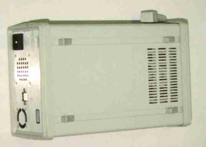
Click to zoom
Application Details
- Equipment Class
- CXX - Communications Rcvr for use w/ licensed Tx and CBs
- Date of Grant
- Nov 11, 1998
- Application Purpose
- Original Equipment
- Date of Application
- Sep 30, 1998
- Equipment Note
- Paging Data Decoder
- Frequency Range
- 929.00000000 - 941.00000000
- Company
- Advanced Signal Corporation
- Country
- United States
Documents & Files
Document Text
Text extracted from the exhibit documents filed with the FCC. Open a document above to read the original.
Users Manual
Version 1.7December, 1997Console Operation 4 - 1 Slot 1-4 The four Slot folders allow you select several parameter settings for each of the four slots. If your SIGNALpro contains less than four DSP Input Cards there will be certain slot folders that are not accessible. DSP Operation Mode - This is used to place the DSP Input Card into different modes of operation. Forward (Assume A8- A10 is R25) is for normal Golay, POCSAG, FLEX, and ReFLEX25 decoding. Forward (Assume A8-A10 is R50) is for ReFLEX50 decoding and may be implemented at a later date. Reverse will be implemented at a later date. RSSI places the DSP Input Card into an RSSI only mode. WHILE IN THIS MODE THE DSP INPUT CARD WILL NOT DECODE PAGING DATA. THEREFORE THE LEDs WILL NOT OPERATE IN THEIR NORMAL CAPACITY. THE FORMAT AND BER LEDs WILL BE GREEN. WHEN YOU HAVE COMPLETED YOUR RSSI ONLY TASK PLEASE REMEMBER TO CHANGE THE DSP MODE SELECTION TO FORWARD. Teletrac POCSAG was implemented for Teletrac, Inc. Sync Measurement - This is used to determine how FLEX Sync Receive Time Measurements are calculated. FLEX frames may be launched on a 1.875 second time boundary. If the launch times slip by 2-3 milliseconds (consult your pager supplier for exact specifications) the pager can lose sync and become inactive until it receives a valid sync. This is a method to determine that the control system is launching FLEX frames in accordance with the protocol specifications. These measurements will rarely be zero because of many factors including delay through your system. Set to Relative if your encoder is not creating FLEX frames synchronous to a GPS time source, or if you are only interested in knowing that the frame just received is accurate relative to the last frame received. A measurement baseline is established with the first frame received and is updated with a new baseline every eight minutes (two cycles). Set to Absolute if your encoder is producing FLEX frames synchronous to a GPS 1PPS reference and is also encoding FLEX frames synchronous to the beginning of a GPS minute. This can be used if you are sharing a channel with another carrier, or if you want to determine if your frames are being received with absolute accuracy. The baseline is established from the GPS 1PPS. FLEX frames must begin exactly at the top of a minute and can be repeated every 1.875 seconds thereafter. The last frame in a minute will be at 58.125 seconds. Absolute Sync measures the error between your FLEX transmission and the fixed 1.875 second time slots. Refer to the Simulcast Delay Spread section, page 6-3. Reset the Metrics Timer - If you select this option all of your metrics will be cleared. This allows you to start collecting new data for each of the static windows (Hourly Usage/Efficiencies, Call Count, Channel Metrics, or Synchronous Receive Times). Depending on channel traffic and on the speed of your PC it may take several minutes for the Windows to clear. Once the new data starts accumulating you will see a new date and time in the Metrics Start Window(s). Version 1.7December, 1997Console Operation 4 - 2 Receiver Operation - Under Frequency (MHz) you can access the pull down menu to select what frequency you would like the internal receiver programmed to. If you want to program a frequency that is not included on the list please contact Advanced Signal for assistance.
Attestation Statements
Page 1 of 1 September 30, 1998 FCC ID: NKO-SIGNAL Federal Communications Commission Authorization and Evaluation Division 7435 Oakland Mills Rd. Columbia, MD 21046 Signed statement as required by Section 2.975 (a)(6) Advanced Signal Corporation’s, two channel receiver Model SIGNALpro has been tested in accordance with the requirements contained in the appropriate Commission regulation. To the best of my knowledge, these tests were performed using measurement procedures consistent with industry or Commission standards and demonstrate that the equipment complies with the appropriate standards. Each unit manufactured, imported or marketed, as defined in the Commission's regulations, will conform to the sample tested within the variations that can be expected due to quantity production and testing on a statistical basis. I further certify that the necessary measurements were made by the independent EMC testing laboratory Radiometrics Midwest Corporation, 12 East Devonwood Avenue in Romeoville, Illinois 60446. Joseph Strzelecki Senior EMC Engineer NARTE EMC-000877-NE Radiometrics Midwest Corp. Authorized Agent for Advanced Signal Corporation Radiometrics Midwest Corporation 12 East Devonwood Romeoville, IL 60446 Phone (815) 293-0772 Fax (815) 293-0820 ± EMC TESTING AND ENGINEERING SERVICES ±
External Photos
FCC ID: NKO-SIGNAL Page 1 of 1 External Photos of EUT
ID Label/Location Info
Page 1 of 1 FCC ID: NKO-SIGNAL FCC ID LABEL AND LOCATION REAR PANEL SILK SCREEN DVANCED SIGNAL Drawing Title: File Name: Document #: Assembly #: 301 Oak, Suite 5-0 Quincy, Il. 62301 Rear Panel Silkscreen rearscrn2.vsd 820-0001-017 810-0001-003 AC Input 90 - 132 VAC or 175 - 264 VAC 47 - 63 Hz 120 VA max fuse = 2A ASCII serial port DVANCED SIGNAL MADE IN U.S.A. WARNING! No operator serviceable parts inside, refer servicing to service trained personnel. 4.700 7.770 (panel size 4.700 x 7.770) FCC ID: NKO-SIGNAL This device complies with Part 15 of the FCC Rules. Operation is subject to the condition that this device does not cause harmful interference.
Internal Photos
FCC ID: NKO-SIGNAL Page 1 of 5 Internal Photos of EUT DC - DC Converter Board (Component Side) DC - DC Converter Board (Foil Side) FCC ID: NKO-SIGNAL Page 2 of 5 Host CPU Board (Component Side) Host CPU Board (Foil Side) FCC ID: NKO-SIGNAL Page 3 of 5 150 MHz Receiver Board (Component Side) 150 MHz Receiver Board (Foil Side) 900 MHz Receiver Board (Component Side) FCC ID: NKO-SIGNAL Page 4 of 5 900 MHz Receiver Board (Foil Side) DSP Board (Foil Side) FCC ID: NKO-SIGNAL Page 5 of 5 DSP Board (Component Side) DSP Board Assembled
Internal Photos
October 1, 1998 Federal Communications Commission 7435 Oakland Mills Road Columbia, MD 21046 RE: Microwave Oven (FCC P.18) Model: MW4592W FCC ID No: A3L3RD4592 FCC Confirmation Number: Gentleman: The above application has been submitted to FCC OET web site on Oct.1, 1998. A check, $940.00 has been directly mailed to Mellon Bank to pay this application. The above equipment uses Samsung magnetron model, OM-75S.. The attached files are, for your reference, as follows: 1. FCC ID Label and location 2. Block Diagram including oscillator information 3. Test report 4. External photo’s 5. Internal photo’s 6. User Manual If you have any question on this application, please let me know at [email protected] or Phone) 408-544-5124. Sincerely Yours, Ben Kim Engineering Manager Samsung Electronics America
Operational Description
FCC ID: NKO-SIGNAL Page 1 of 2 EUT Description The SIGNALpro is a data analysis tool used to decode paging data for system diagnostics and performance evaluation. The product may be operated as a stand alone unit to gather and store data or in conjunction with a PC to provide real time on- screen presentation of paging data. Reception of paging data can be accomplished using a built-in 900 MHz. or 150 MHz. receiver or by connection to an external receiver such as a communications or service monitor. Data is then decoded on the DSP card and passed to the HOST card for transmission to the PC. Sales are limited to paging service providers, law enforcement, and paging equipment manufacturers. The SIGNALpro hardware consists of five circuit boards, backplane board, power supply, and aluminum enclosure or case. The circuit board and power supply functions are as follows: 1. Power Supply - Power-One MAP55-1024 AC to 24 VDC power supply. 2. Backplane - Provides interconnection between all circuit modules. 3. DC/DC Converter Board - Provides +12, -12, an +5VDC power sources for all circuit modules. Accepts input from the power supply module or front panel DC Input . 4. Oscillator/GPS Board - Provides an ovenized 10MHz. reference oscillator signal and houses the GPS receiver module. 5. HOST/CPU Board - Provides communications between the SIGNALpro and PC, data storage for the DSP and Receiver modules. 6. DSP Card - Performs decoding of paging data by detecting paging format and rate and applying an appropriate decoding algorithm. 7. Receiver - Dual conversion synthesized receiver with two possible configurations, a wide band version (5 kHz. Maximum system deviation) and a narrow band version (2.5 kHz. Maximum ). I/O Connections: Front Panel: 1. DC Input - an input intended for connection to a vehicle 12VDC power source using a cigarette lighter adapter. 2. MHz. IN/OUT BNC connector - With the front panel switch set to the internal position the ovenized oscillator provides a 10MHz. output to this connector to be used as a reference for other test equipment. With the front panel switch set to Ext. an external 10 MHz. reference signal may be input at this connector. 3. GPS Ant - Connection point for the external GPS receive antenna. 1575.42 MHz. operating frequency. 4. Spare Outputs - No function. 5. 1PPS - 1 Hz. timing reference output. 6. Console GUI - Connection port between the SIGNALpro and the PC providing bi-directional RS-232 communications at 57.6 kBPS. 7. Rx Ant - antenna connection point for the internal 900 or 150 MHz. receiver. 8. RX Audio Out - Demodulated audio output from the optional internal receiver module. Normally connected to the DSP input. FCC ID: NKO-SIGNAL Page 2 of 2 9. Slot 2 Input - Audio input to the DSP card. Input sources include the internal receiver via the RX Audio Out port, external receiver, or 4 Level Out port. 10. Level Out - Audio output from the DSP MSB/LSB to 4 level interface. Connected to the Slot 2 Input in place of the receiver connection. Parallel I/O - 1. Pins 1, 2, 8 - Ground 2. Pin 3 - MSB Input 3. Pin 4 - LSB Input 4. Pin 5, 6 - +5VDC 5. Pin 7 - Audio Invert Input 6. Pin 9 - Not used 7. Pin 10 - Scope trigger 1 output Rear Panel 1. AC Input - 90-132, 175 - 264 vac, 47-63 Hz. input. 2. Alternate Port - Not used. 3. ASCII Serial port - used for factory test purposes. Clock Frequencies: Oscillator/GPS Card: 10 MHz., 5MHz. Both signals distributed by the backplane to the HOST and DSP cards. HOST/CPU: 1. 16.667 MHz. Clock for the 68302 processor. Confined to the HOST card. 2. 4XOUT - 96kHz. Signal used on the HOST and distributed to the DSP card as BUS4X. 3. MHz. - 4.8 MHz. signal used on the HOST and distributed to the DSP card as BUS4_8. 4. 4XDIV - 24kHz. Signal confined to the HOST. DSP: 1 MHz. Clock for the TMS320C26 DSP. Confined to the DSP card. 2 48kHz. Signal confined to DSP card. RECEIVER CARD: 1. 21.4 MHz. IF. 2. 455kHz. IF. 3. Low side Injection 1 st L.O. operating in the range of 907.6 to 919.6 MHz. to cover possible receive frequencies in the range of 929-941MHz. 4. High side Injection 1 st L.O. operating in the range of 172.4 to 180.4 MHz. to cover possible receive frequencies in the range of 151.0 to 159.0 MHz . 5. MHz. 2 nd L.O.
Contact Information
Applicant
Thomas Brink(Operations Director)
Technical Contact
Radiometrics Midwest CorporationJoseph R Strzelecki
[email protected]815-293-0772
12 East Devonwood Av. · Romeoville, Illinois · United States
Non-Technical Contact
Radiometrics Midwest CorporationJoan E Strzelecki
[email protected]815-293-0772
Test Firm
Radiometrics Midwest CorporationJoseph Strzelecki
815-293-0772Fax: 815-293-0820
Technical Specifications
| # | Rule Parts | Frequency Range | Power Output |
|---|---|---|---|
| 2 | 15B | 929 MHz - 941 MHz | - |
Other Applications from Advanced Signal Corporation

NKO-SIGPRO
Nov 03, 1999Paging Data Receiver
Equipment Class
CXX - Communications Rcvr for use w/ licensed Tx and CBsNKO-SIGNALPRO
Jul 31, 1997CXX - Communications Rcvr for use w/ licensed Tx and CBs
Equipment Class
CXX - Communications Rcvr for use w/ licensed Tx and CBs