NKTPF328MIRROR 2
Platform2 International LimitedApplication Details
- Equipment Class
- DSS - Part 15 Spread Spectrum Transmitter
- Date of Grant
- Feb 26, 2014
- Application Purpose
- Original Equipment
- Date of Application
- Feb 26, 2014
- Equipment Note
- MIRROR 2
- Frequency Range
- 2402.00000000 - 2480.00000000
- Country
- Hong Kong
Documents & Files
Document Text
Text extracted from the exhibit documents filed with the FCC. Open a document above to read the original.
Users Manual
How to turn on and use in a pair ... (1/2) R L 1.Slide the switch to the “ON” position 2.Hearing the Opening Sound 3.“Blue” indicator lights up behind the badge. 4.Speakers will synchronize to each others within 30s automatically, and will prompt “Right Channel” 1.Slide the switch to the “ON” position 2.Hearing the Opening Sound 3.“Blue” indicator lights up behind the badge. 4.Speakers will synchronize to each others within 30s automatically, and will prompt “Left Channel” How to turn on and use in a pair ... (2/2) L Normal Pairing: 5a. Slide and hold the switch to the “Pair” Position 6a. Hear “Ready to Connect” 7a. Search and Pair “Mirror BoomBox2” 8a. When your device is connected to the system, will prompt “We are connected” from Speaker 9a. Play music from your device L NFC Pairing: 5a. Enable the NFC feature on the phone 6a. Tap your device on the Back of the Mirror BoomBox2 to pair 7a. When your device is connected to the system, will prompt “We are connected” from Speaker 8a. Play music from your device How to turn on and use individually ... R L 1.Slide the switch to the “ON” position 2.Hearing the Opening Sound 3.“Blue” indicator lights up behind the badge. 5. Slide and hold the switch to the “Pair” Position 6. Hear “Ready to Connect” 7. Search and Pair “Mirror BoomBox2” 8. When your device is connected to the system, will prompt “We are connected” from Speaker 9. Play music from your device * Once both Speakers being turned ON, the Wireless Stereo will automatically fromed OR How to control the Speaker ... 1 2 3 1.Play / Pause (Press down the whole speaker) 2.Volume up (Touch) 3.Volume down (Touch) 4.Operation LED indicator 5.USB Power * Identical Operations on both Speakers LED Indicator Remark •Visit the Support Section from http://xxxxxxxxxxxxx to view the Manual. •If no Bluetooth Connection exceeds 15 minutes, Mirror2 will automatically switch into Standby mode for energy saving. •Fully charged once a month •“0000” is the passcode if necessary during pairing Warning Please read these safety warnings and cautions carefully to ensure your personal safety and prevent property damage. Fire and Electric Shock Hazard • Do not expose your Mirror2 to liquid, moisture, humidity, or rain. Do not use the Mirror2 near a bathtub, sink, sauna, pool, or steam room. Exposure of the Mirror2 to moisture could result in electric shock. • Do not place any items filled with liquids, such as glasses, vases or similar objects, on top of the device. • Do not drop, disassemble, open, crush, bend, deform, puncture, shred, microwave, incinerate, paint, or insert any objects into the Mirror2. Such actions could result in electric shock. • Clean the Mirror2 only with a dry cloth. • Do not expose your Mirror2 to extremely high or low temperatures. • Do not expose your Mirror2 to sources of excessive heat, such as sunlight, fire or similar. Do not place your Mirror2 near an open fire, such as gas burners, candles or fireplaces, and avoid contact with direct solar radiation. Do not place any candles or other open flames on the device. Make sure that the Mirror2 is exposed to sufficient ventilation. Do not block the vent holes with objects such as magazines, tablecloths or similar items.Battery/Charger Hazard • Do not dispose of your Mirror2 into a fire. The battery could explode causing injury or death. • Only charge the battery in accordance with the user instructions supplied with the Mirror Boombox . • Do not attempt to disassemble the Mirror2 or force open the built-in battery because this may result in electric shock. • Do not charge the Mirror2 in damp areas or in extremely high or low temperatures because this could result in electric shock. • Do not clean the Mirror2 when it is being charged. Always unplug the charger first before cleaning the Mirror Boombox . • Set up the device in such a way that the mains plug is always easily accessible and you can unplug it quickly in the event of an emergency.Automobile Accident Hazard • Do not leave or store the Mirror Boombox or any of its accessories near or over your automobile’s air bag because serious injury may result when an airbag deploys.Fall Hazard • Do not place the Mirror2 on high surfaces such as shelves. During music playback the Mirror2 may move which could cause the Mirror2 fall from the edge.Caution • Do not use abrasive cleaners to clean your Mirror2 because this could cause scratches and damage. • Do not bring your Mirror2 in to contact with any sharp objects because this could cause scratches and damage. • Do not insert anything into your Mirror2 unless otherwise specified in the user instructions. This may damage the internal components. • Do not attempt to repair, modify, or disassemble your Mirror Boombox yourself, it does not contain any user-serviceable components. • Do not attempt to replace your Mirror2 battery, it is built-in and is not changeable. • Observe all signs and displays that require an electrical device or RF radio product to be switched off in designated areas. • Turn off your Mirror2 prior to boarding an aircraft. Do not use the Mirror2 inside an aircraft unless allowed by your airline • Dispose of the Mirror2 and the Mirror2 ‘s battery in accordance with local regulations. Do not dispose of the battery with regular household waste. FCC Statement This equipment has been tested and found to comply with the limits for a Class B digital device, pursuant to Part 15 of the FCC Rules. These limits are designed to provide reasonable protection against harmful interference in a residential installation. This equipment generates use and can radiate radio frequency energy and, if not installed and used in accordance with the instructions, may cause harmful interference to radio communications. However, there is no guarantee that interference will not occur in a particular installation. If this equipment does cause harmful interference to radio or television reception, which can be determined by turning the equipment off and on…
Text truncated - open the document above for the full version.
Cover Letter(s)
2013-12-05 Nemko Canada Inc 303 River Road Ottawa, Ontario, Canada K1V 1H2 Attn: Director of Certification Authority to Act as Agent On our behalf, I appoint Daria Liu of NEMKO Shenzhen ,Unit CD, Floor 10,Tower 2, Kefa Road 8#,Hi-Technology Park, Nanshan District,Shenzhen ,China (Name and address,person). to act as our agent in the preparation of this application for equipment certification. I certify that submitted documents properly describe the device or system for which equipment certification is sought. I also certify that each unit manufactured, imported or marketed, as defined in the Federal Communications Commission’s regulations will have affixed to it a label identical to that submitted for approval with this application. For instances where our authorized agent signs the application for certification on our behalf, I acknowledge that all responsibility for complying with the terms and conditions for certification, as specified by Nemko Canada Inc, still resides with Platform2 International Limited/ Rm.905 Seapower Center 73 Lei Muk Road, Kwai Chung Hong Kong ( applicant name and address). Dated this 2013-12-05 Agency agreement expiration date: Usually Give 8 - 12 Months By: Winny Mak Signature Printed Title: Exective Assistant to CEO On behalf of : Platform2 International Limited Telephone: +852 24227106 Extension: 631
Cover Letter(s)
2013-12-05 Equipment Autorisation Division Federal Communications Commission 7435 Oakland Mills Road Columbia, MD 21046 FCC ID: NKTPF328 Product Name: MIRROR² Request for Confidentiality Pursuant to Sections 0.457 and 0.459 of the commissions rules, we hereby request that the following documents be held confidential: (List here the documents for which you are seeking confidentiality – for example ...) • Schematics • Block diagram • Operation description These materials contain trade secrets and proprietary information and are not customarily released to the public. The public disclosure of this information might be harmful to the company and provide unjustified benefits to our competitors. Dated this 2013-12-05 Agency agreement expiration date: Usually Give 8 - 12 Months By: Winny Mak Signature Printed Title: Exective Assistant to CEO On behalf of : Platform2 International Limited Telephone: +852 24227106 Extension: 631
External Photos
EUT Figu Figu T photo -det ure 1 EUT ure 2 EUT tails- T External P T External P hoto hoto Figu Figu ure 3 EUT ure 4 EUT T External P T External P hoto hoto Figu Figu ure 5 EUT ure 6 EU T External P UT External hoto Photo
Internal Photos
EUT Figu Figu T photo -det ure 1 EUT ure 2 EUT tails- T Internal Ph T Internal Ph hoto hoto Figu Figu ure 3 EUT ure 4 EUT T Internal Ph T Internal Ph hoto hoto Figu Figu ure 5 EUT ure 6 EU T Internal Ph UT Internal hoto Photo Figu Figu ure 7 EU ure 8 EU UT Internal UT Internal Photo Photo Figu ure 9 EU UT Internal Photo
RF Exposure Info
Acc The tes [( m sep 10- f P cal T Wor (0. The ording to 1-g and 1 t separat max. power aration d g extremi f(GHz) is Power and culation The result se case i 576 /5) · n SAR ev a o 447498 D 10-g SAR t tion dista r of chann distance, m ty SAR, w the RF ch distance t is round s as belo [√2.402( aluation i RF Expo D01 Genera test exclu ances ≤ 50 nel, inclu mm)] ·[√ where hannel tra are round ded to one ow: [2402M (GHz)]= 0. s not re q osure eval al RF Expo usion thre 0 mm are d uding tune f(GHz)] ≤ ansmit fre ded to the e decimal MHz -2.393 .179 <3.0 quired luation osure Guid esholds fo determined e-up toler ≤ 3.0 for equency in e nearest place fo r 3dBm(0.576 for 1-g dance v05 or 100 MHz d by: rance, mW) 1- g SAR a n GHz mW and m m r comparis 6mW) outpu SAR z to 6 GHz /(min. te and ≤ 7.5 m before son ut power] z at est for
Test Report
Platform2 International Limited Page 1 of 109 FCC ID NKTPF328 Reference No.: 248448 FCC Test Report FCC EVALUATION REPORT FOR CERTIFICATION Project Reference No. 248448 Product MIRROR² Brand Name N/A Model PF328 Alternate Model N/A Tested according to FCC Rules and Regulations Part 15 Subpart C 2013, 15.247 ANSI C63.4-2009 Tested in period 2013-12-05 to 2013-12-13 Issued date 2013-12-15 Name and address of the Test House Nemko Shanghai Ltd Shenzhen Branch Unit CD, Floor 10, Tower 2, Kefa Road 8#, Hi-Technology Park, Nanshan District, Shenzhen, China Phone : +86 755 8221 0420 Fax : +86 755 8221 3363 Tested by 2013-12-15 Zone Peng date Verified by 2013-12-16 Daria Liu date This form is only for use by Nemko, or by others according to special agreement with Nemko. The report may be reproduced infull. Partial reproduction may only be made with the written content of Nemko Shanghai. This report applies only to the sample(s) tested. It is the manufacturer’s responsibility to assure the additional production units of this product are manufactured with identical electrical and mechanical components. Platform2 International Limited Page 2 of 109 FCC ID NKTPF328 Reference No.: 248448 Contents of This Report 1. Client Information ............................................................................................................................... 4 1.1 Applicant .................................................................................................................................... 4 1.2 Manufacturer .............................................................................................................................. 4 1.3 Scope ......................................................................................................................................... 4 2. Equipment under Test (EUT) .............................................................................................................. 5 2.1 Identification of EUT .................................................................................................................. 5 2.2 Detail spec: ................................................................................................................................ 5 2.3 Additional Information Related to Testing .................................................................................. 5 3. General Test Conditions ...................................................................................................................... 6 3.1 Location ..................................................................................................................................... 6 3.2 Operating Environment .............................................................................................................. 6 3.3 Operating During Test ................................................................................................................ 6 3.4 Test Equipment .......................................................................................................................... 6 4. Measurement Uncertainty ................................................................................................................... 6 5. Conducted Emission (150 KHz to 30 MHz) ................................................................................... 7 5.1 Test Procedure ........................................................................................................................... 7 5.2 Measurement Equipment ........................................................................................................... 7 5.3 Test Result ................................................................................................................................. 7 5.3.1 Diagram 5-1 ................................................................................................................................... 8 5.3.2 Diagram 5-2 ................................................................................................................................... 9 6. Radiated Electromagnetic Disturbances ........................................................................................... 10 6.1 Test Procedure ......................................................................................................................... 10 6.2 Measurement Equipment ......................................................................................................... 10 6.3 Test Result ............................................................................................................................... 11 6.3.2 Diagram 6-2 ................................................................................................................................. 15 6.3.3 Diagram 6-3 ................................................................................................................................. 16 6.3.4 Diagram 6-4 ................................................................................................................................. 19 6.3.5 Diagram 6-5 ................................................................................................................................. 22 6.3.6 Diagram 6-6 ................................................................................................................................. 24 6.3.7 Diagram 6-7 ................................................................................................................................. 26 6.3.8 Diagram 6-8 ................................................................................................................................. 29 6.3.9 Diagram 6-9 ................................................................................................................................. 32 6.3.10 Diagram 6-10 ........................................................................................................…
Text truncated - open the document above for the full version.
Test Report
Platform2 International Limited Page 55 of 109 FCC ID NKTPF328 Reference No.: 248448 Platform2 International Limited Page 56 of 109 FCC ID NKTPF328 Reference No.: 248448 6.3.18 Diagram 6-18 Platform2 International Limited Page 57 of 109 FCC ID NKTPF328 Reference No.: 248448 Platform2 International Limited Page 58 of 109 FCC ID NKTPF328 Reference No.: 248448 6.3.19 Diagram 6-19 Platform2 International Limited Page 59 of 109 FCC ID NKTPF328 Reference No.: 248448 Platform2 International Limited Page 60 of 109 FCC ID NKTPF328 Reference No.: 248448 Platform2 International Limited Page 61 of 109 FCC ID NKTPF328 Reference No.: 248448 6.3.20 Diagram 6-20 Platform2 International Limited Page 62 of 109 FCC ID NKTPF328 Reference No.: 248448 Platform2 International Limited Page 63 of 109 FCC ID NKTPF328 Reference No.: 248448 Platform2 International Limited Page 64 of 109 FCC ID NKTPF328 Reference No.: 248448 7. 20 dB & 99%bandwidth Test 7.1 Test Procedure Clause 15.215(c) 20dB Bandwidth: Intentional radiators operating under the alternative provisions to the general emission limits, as contained in15.217 through 15.257 and in Subpart E of this part, must be designed to ensure that the 20 dB bandwidth of the emission, or whatever bandwidth may otherwise be specified in the specific rule section under which the equipment operates, is contained within the frequency band designated in the rule section under which the equipment is operated. The requirement to contain the designated bandwidth of the emission within the specified frequency band includes the effects from frequency sweeping, frequency hopping and other modulation techniques that may be employed as well as the frequency stability of the transmitter over expected variations in temperature and supply voltage. If a frequency stability is not specified in the regulations, it is recommended that the fundamental emission be kept within at least the central 80% of the permitted band in order to minimize the possibility of out-of-band operation. 7.2 Measurement Equipment Item Equipment Last Calibration Type Serial No. Manufacturer 1 Spectrum May.08, 13 E4446A US44300459 Agilent 7.3 Test Result: GFSK diagrams are as below: Modulation Channel 99% bandwidth (kHz) 20dB bandwidth (kHz) GFSK CHL 831.49 843.6 CHM 831.09 838.2 CHH 833.17 848.1 Platform2 International Limited Page 65 of 109 FCC ID NKTPF328 Reference No.: 248448 Platform2 International Limited Page 66 of 109 FCC ID NKTPF328 Reference No.: 248448 Platform2 International Limited Page 67 of 109 FCC ID NKTPF328 Reference No.: 248448 Modulation Channel 99% bandwidth(MHz) 20dB bandwidth(MHz) 8DPSK CHL 1.2272 1.211 CHM 1.1778 1.207 CHH 1.1508 1.208 8DPSK diagrams are as below: Platform2 International Limited Page 68 of 109 FCC ID NKTPF328 Reference No.: 248448 Platform2 International Limited Page 69 of 109 FCC ID NKTPF328 Reference No.: 248448 Modulation Channel 99% bandwidth(MHz) 20dB bandwidth(MHz) π/4 DQPSK CHL 1.2695 1.210 CHM 1.2066 1.215 CHH 1.1691 1.211 π/4 DQPSK diagrams are as below: Platform2 International Limited Page 70 of 109 FCC ID NKTPF328 Reference No.: 248448 Platform2 International Limited Page 71 of 109 FCC ID NKTPF328 Reference No.: 248448 8. Band Edge Compliance Test 8.1 Test Procedure According to §15.247(d), in any 100 kHz bandwidth outside the frequency bands in which the spread spectrum intentional radiator in operating, the radio frequency power that is produced by the intentional radiator shall be at least 20dB below that in the 100kHz bandwidth within the band that contains the highest level of the desired power. 8.2 Measurement Equipment Item Equipment Last Calibration Type Serial No. Manufacturer 1 Spectrum May.08, 13 E4446A US44300459 Agilent 8.3 Test Result REMARK : Hopping off and Hopping on modes all have been tested, Hopping off mode is the worse case and recorded as below GFSK Hopping off CHL : Platform2 International Limited Page 72 of 109 FCC ID NKTPF328 Reference No.: 248448 Platform2 International Limited Page 73 of 109 FCC ID NKTPF328 Reference No.: 248448 GFSK Hopping off CHM: Platform2 International Limited Page 74 of 109 FCC ID NKTPF328 Reference No.: 248448 Platform2 International Limited Page 75 of 109 FCC ID NKTPF328 Reference No.: 248448 GFSK Hopping off CHH : Platform2 International Limited Page 76 of 109 FCC ID NKTPF328 Reference No.: 248448 Platform2 International Limited Page 77 of 109 FCC ID NKTPF328 Reference No.: 248448 8DPSK Hopping off CHL : Platform2 International Limited Page 78 of 109 FCC ID NKTPF328 Reference No.: 248448 Platform2 International Limited Page 79 of 109 FCC ID NKTPF328 Reference No.: 248448 8DPSK Hopping off CHM :
Test Report
Platform2 International Limited Page 80 of 109 FCC ID NKTPF328 Reference No.: 248448 Platform2 International Limited Page 81 of 109 FCC ID NKTPF328 Reference No.: 248448 8DPSK Hopping off CHH : Platform2 International Limited Page 82 of 109 FCC ID NKTPF328 Reference No.: 248448 Platform2 International Limited Page 83 of 109 FCC ID NKTPF328 Reference No.: 248448 π/4 DQPSK Hopping off CHL : Platform2 International Limited Page 84 of 109 FCC ID NKTPF328 Reference No.: 248448 Platform2 International Limited Page 85 of 109 FCC ID NKTPF328 Reference No.: 248448 π/4 DQPSK Hopping off CHM : Platform2 International Limited Page 86 of 109 FCC ID NKTPF328 Reference No.: 248448 Platform2 International Limited Page 87 of 109 FCC ID NKTPF328 Reference No.: 248448 π/4 DQPSK Hopping off CHH : Platform2 International Limited Page 88 of 109 FCC ID NKTPF328 Reference No.: 248448 Platform2 International Limited Page 89 of 109 FCC ID NKTPF328 Reference No.: 248448 9. Carrier Frequency Separation Test 9.1 Test Procedure Frequency hopping systems shall have hopping channel carrier frequencies separated by a minimum of 25 kHz or the 20 dB bandwidth of the hopping channel, whichever is greater. Alternatively, freq hopping systems operating in the 2400–2483.5 MHz band may have hopping channel carrier frequencies that are separated by 25 kHz or two-thirds of the 20 dB bandwidth of the hopping channel, whichever is greater, provided the systems operate with an output power no greater than 125 mW. The system shall hop to channel frequencies that are selected at the system hopping rate from a pseudo randomly ordered list of hopping frequencies. Each frequency must be used equally on the average by each transmitter. The system receivers shall have input bandwidths that match the hopping channel bandwidths of their corresponding transmitters and shall shift frequencies in synchronization with the transmitted signals. The peak detector was used with 100 kHz/300 kHz RBW/VBW 9.2 Measurement Equipment Item Equipment Last Calibration Type Serial No. Manufacturer 1 Spectrum May.08, 13 E4446A US44300459 Agilent 9.3 Test Result Widest channel bandwidth was 1215kHz. So Two-thirds is 810kHz and greater than 25kHz . Result : Pass. Carrier Frequency Separation=1MHz > 810kHz Platform2 International Limited Page 90 of 109 FCC ID NKTPF328 Reference No.: 248448 10. Output Power Test 10.1 Test Procedure The maximum peak conducted output power of the intentional radiator shall not exceed the following: (1) For frequency hopping systems operating in the 2400–2483.5 MHz band employing at least 75 non-overlapping hopping channels, and all frequency hopping systems in the 5725–5850 MHz band: 1 W. For all other frequency hopping systems in the 2400–2483.5 MHz band: 0.125 W. (4) The conducted output power limit specified in paragraph (b) of this section is based on the use of antennas with directional gains that do not exceed 6 dBi. Except as shown in paragraph (c) of this section, if transmitting antennas of directional gain greater than 6 dBi are used, the conducted output power from the intentional radiator shall be reduced below the stated values by the amount in dB that the directional gain of the antenna exceeds 6 dBi. 10.2 Measurement Equipment Item Equipment Last Calibration Type Serial No. Manufacturer 1 Spectrum May.08, 13 E4446A US44300459 Agilent 10.3 Test Result Remark : 1:RBW=2MHz VBW=3MHz PK detector for GFSK Cable loss is 1dB and it have been set in Spectrum GFSK: Frequency, MHz Result Output power, dBm <Power Limit, dBm 2402 -2.393 30.00 2441 -2.425 30.00 2480 -4.083 30.00 Platform2 International Limited Page 91 of 109 FCC ID NKTPF328 Reference No.: 248448 Diagram of GFSK is as below: Platform2 International Limited Page 92 of 109 FCC ID NKTPF328 Reference No.: 248448 Platform2 International Limited Page 93 of 109 FCC ID NKTPF328 Reference No.: 248448 Remark : 1:RBW=2MHz VBW=3MHz PK detector for 8DPSK Cable loss is 1dB and it have been set in Spectrum 8DPSK: Diagram of 8DPSK is as below: Frequency, MHz Result Output power, dBm <Power Limit, dBm 2402 -2.604 30.00 2441 -2.768 30.00 2480 -4.819 30.00 Platform2 International Limited Page 94 of 109 FCC ID NKTPF328 Reference No.: 248448 Platform2 International Limited Page 95 of 109 FCC ID NKTPF328 Reference No.: 248448 Remark : 1:RBW=2MHz VBW=3MHz PK detector forπ/4 DQPSK Cable loss is 1dB and it have been set in Spectrum π/4 DQPSK: Diagram of π/4 DQPSK is as below: Frequency, MHz Result Output power, dBm <Power Limit, dBm 2402 -2.680 30.00 2441 -2.897 30.00 2480 -5.134 30.00 Platform2 International Limited Page 96 of 109 FCC ID NKTPF328 Reference No.: 248448 Platform2 International Limited Page 97 of 109 FCC ID NKTPF328 Reference No.: 248448 11. NUMBER OF HOPPING FREQUENCY TEST 11.1 Test Procedure Frequency hopping systems in the 2400–2483.5 MHz band shall use at least 15 channels. The average time of occupancy on any channel shall not be greater than 0.4 seconds within a period of 0.4 seconds multiplied by the number of hopping channels employed. Frequency hopping systems may avoid or suppress transmissions on a particular hopping frequency provided that a minimum of 1 5 channels are used. 11.2 Measurement Equipment Item Equipment Last Calibration Type Serial No. Manufacturer 1 Spectrum May.08, 13 E4446A US44300459 Agilent 11.3 Test Result Test mode: Transmitter Hopping on Number of channels used Minimum number of channels limit Margin 79 15 64 Platform2 International Limited Page 98 of 109 FCC ID NKTPF328 Reference No.: 248448 11.3.1 Diagram Platform2 International Limited Page 99 of 109 FCC ID NKTPF328 Reference No.: 248448 12. DWELL TIME TEST 12.1 Test Procedure Frequency hopping systems in the 2400–2483.5 MHz band shall use at least 15 channels. The average time of occupancy on any channel shall not be greater than 0.4 seconds within a period of 0.4 seconds multiplied by the number of hopping channels employed. Frequency hopping systems may avoid or suppress transmissions on…
Text truncated - open the document above for the full version.
Contact Information
Applicant
Winny Mak(Exective Assistant to CEO)
Test Firm
Audix Technology (Shenzhen) Co., Ltd.Smart Tsai
Technical Specifications
| # | Rule Parts | Frequency Range | Power Output |
|---|---|---|---|
| 1 | 15C | 2.40 GHz - 2.48 GHz | 576.00 µW |
Other Applications from Platform2 International Limited
NKTUD-1404
Jul 13, 2015Sound bar
Equipment Class
DTS - Digital Transmission System
NKTUD-1404S
Jul 13, 2015Subwoofer
Equipment Class
DSS - Part 15 Spread Spectrum Transmitter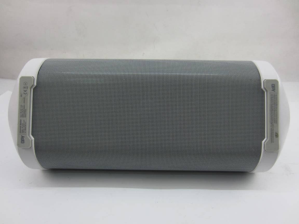
NKTDF-1417
May 11, 2015Bluetooth Speaker
Equipment Class
DSS - Part 15 Spread Spectrum Transmitter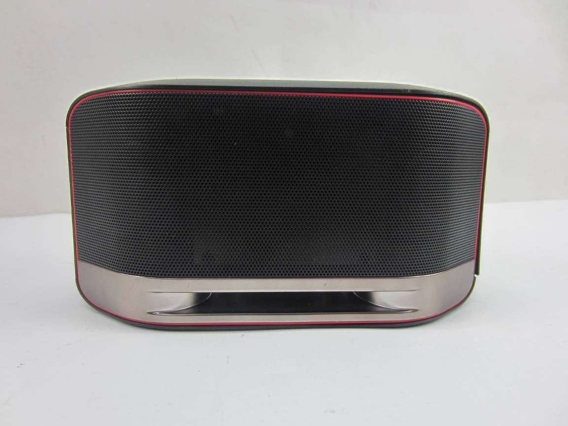
NKTUD-1402
Apr 14, 2015Bluetooth / WiFi Speaker
Equipment Class
DSS - Part 15 Spread Spectrum Transmitter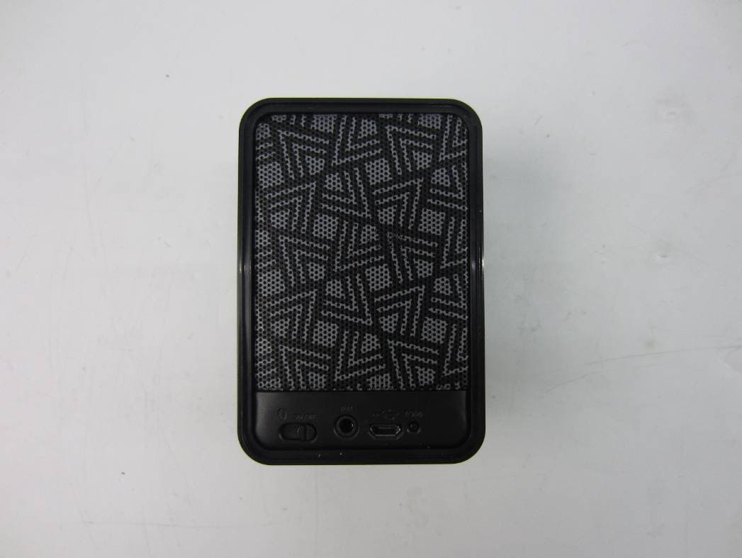
NKTDF-1421
Jan 15, 2015Bluetooth Speaker
Equipment Class
DXX - Part 15 Low Power Communication Device Transmitter