NMF-CT2-001Cellular Transceiver with Modem
Raytheon Company dba Raytheon Systems Co.
Click to zoom
Application Details
- Equipment Class
- TNB - Licensed Non-Broadcast Station Transmitter
- Date of Grant
- Jan 18, 1999
- Application Purpose
- Original Equipment
- Date of Application
- Oct 19, 1998
- Equipment Note
- Cellular Transceiver with Modem
- Frequency Range
- 824.04000000 - 849.00000000
- Country
- United States
Documents & Files
Document Text
Text extracted from the exhibit documents filed with the FCC. Open a document above to read the original.
Users Manual
TITLE: CELL-TRAC™ II User’s Manual DOCUMENT NO: Raytheon Proprietary Protect from unauthorized use, disclosure or release in accordance with signed Non Disclosure Agreement ORIGINATORDATEREVISION DATEPAGE 1OF 27 1.1 Exhibit 8 Users Manual Exhibit 8 includes the current document that is being used as the user’s manual for the CELL- TRAC™II. TITLE: CELL-TRAC™ II User’s Manual DOCUMENT NO: Raytheon Proprietary Protect from unauthorized use, disclosure or release in accordance with signed Non Disclosure Agreement ORIGINATORDATEREVISION DATEPAGE 2OF 27 User’s Manual CELL-TRAC™ II PRELIMINARY Document No APPROVALSDate Prepared By SYS Engr Origination Date HW Engr Revision SW Engr Revision Date Proj Mgmt Raytheon Proprietary Protect from unauthorized use, disclosure or release in accordance with signed Non Disclosure Agreement TITLE: CELL-TRAC™ II User’s Manual DOCUMENT NO: Raytheon Proprietary Protect from unauthorized use, disclosure or release in accordance with signed Non Disclosure Agreement ORIGINATORDATEREVISION DATEPAGE 3OF 27 Warning While this device is in operation, a separation distance of at least 20 centimeters (8 inches) should be maintained between the radiating antenna, mounted on the vehicle, and the body of the user or nearby persons. If the optional handset is installed and phone calls of more then 10 minutes in duration are made, insure that while this device is in operation, a separation distance of at least 36 centimeters (14 inches) should be maintained between the radiating antenna and the body of the user or nearby persons. Warning While this device is in operation a separation distance of at least 3.048 meters (10 feet) should be maintained between the radiating antenna, mounted on the vehicle, to any blasting operation, including the blasting circuit wiring and/or electric detonators. Caution Changes or modification not expressly approved by RAYTHEON TI SYSTEMS could void the user’s authority to operate this equipment. TITLE: CELL-TRAC™ II User’s Manual DOCUMENT NO: Raytheon Proprietary Protect from unauthorized use, disclosure or release in accordance with signed Non Disclosure Agreement ORIGINATORDATEREVISION DATEPAGE 4OF 27 TABLE OF CONTENTS 1. SCOPE.......................................................................................................... 6 2. REFERENCES .............................................................................................. 6 2.1 Reference Standards & Documents ...................................................... 6 2.2 List Of Acronyms.................................................................................... 6 2.3 Definitions .............................................................................................. 6 3. OPERATIONAL OVERVIEW ........................................................................ 7 3.1 Remote Asset Visibility Approach .......................................................... 7 3.1.1 RAV System Description. .............................................................. 7 3.2 CELL-TRAC™ II Description.................................................................. 8 3.2.1 Operating Modes ........................................................................... 9 3.2.1.1 Standby Mode. ..................................................................... 10 3.2.1.2 Continuous Mode. ............................................................... 10 3.2.1.3 Power Save Mode. ............................................................... 10 3.2.2 Communications ............................................................................ 11 3.2.2.1 Communication Protocols ..................................................... 11 3.2.2.2 Call Error Handling ................................................................ 12 3.2.2.3 Message Definitions .............................................................. 13 3.2.3 Processing Functions .................................................................... 13 3.2.3.1 Data Storage ......................................................................... 13 3.2.3.2 Scheduled Events ................................................................. 14 3.2.3.3 Exceptions............................................................................. 17 3.2.3.4 Check-in Reports................................................................... 18 3.2.4 Software Updates. ......................................................................... 19 3.2.5 Delivered Configuration ................................................................. 19 3.2.5.1 Shipping Considerations ....................................................... 19 3.2.5.2 Cellular Registration and Activation....................................... 19 3.2.6 CELL-TRAC™ II Installation. ......................................................... 19 3.2.7 Asset Registration.......................................................................... 19 3.2.7.1 Association Approach............................................................ 20 3.2.7.2 Registration Process. ............................................................ 20 3.2.8 Functional Elements ...................................................................... 21 3.2.8.1 Cellular Modem. .................................................................... 21 3.2.8.2 GPS Receiver........................................................................ 22 3.2.8.3 System Processors. .............................................................. 22 3.2.8.4 Real Time Clock (RTC). ........................................................ 22 3.2.8.5 Data Memory......................................................................... 22 3.2.8.6 Usage Meter.......................................................................... 23 3.2.8.7 External I/O. .......................................................................... 23 3.2.8.8 Local Control Port (LCP). ...................................................... 23…
Text truncated - open the document above for the full version.
Users Manual
TITLE: CELL-TRAC™ II User’s Manual DOCUMENT NO: Raytheon Proprietary Protect from unauthorized use, disclosure or release in accordance with signed Non Disclosure Agreement ORIGINATORDATEREVISION DATEPAGE 1OF 27 1.1 Exhibit 8 Users Manual Exhibit 8 includes the current document that is being used as the user’s manual for the CELL- TRAC™II. TITLE: CELL-TRAC™ II User’s Manual DOCUMENT NO: Raytheon Proprietary Protect from unauthorized use, disclosure or release in accordance with signed Non Disclosure Agreement ORIGINATORDATEREVISION DATEPAGE 2OF 27 User’s Manual CELL-TRAC™ II PRELIMINARY Document No APPROVALSDate Prepared By SYS Engr Origination Date HW Engr Revision SW Engr Revision Date Proj Mgmt Raytheon Proprietary Protect from unauthorized use, disclosure or release in accordance with signed Non Disclosure Agreement TITLE: CELL-TRAC™ II User’s Manual DOCUMENT NO: Raytheon Proprietary Protect from unauthorized use, disclosure or release in accordance with signed Non Disclosure Agreement ORIGINATORDATEREVISION DATEPAGE 3OF 27 Warning While this device is in operation, a separation distance of at least 50 centimeters (20 inches) should be maintained between the radiating antenna, mounted on the vehicle, and the body of the user or nearby persons in order to meet the FCC RF exposure guidelines. Warning While this device is in operation a separation distance of at least 3.048 meters (10 feet) should be maintained between the radiating antenna, mounted on the vehicle, to any blasting operation, including the blasting circuit wiring and/or electric detonators. Caution Changes or modification not expressly approved by RAYTHEON TI SYSTEMS could void the user’s authority to operate this equipment. TITLE: CELL-TRAC™ II User’s Manual DOCUMENT NO: Raytheon Proprietary Protect from unauthorized use, disclosure or release in accordance with signed Non Disclosure Agreement ORIGINATORDATEREVISION DATEPAGE 4OF 27 TABLE OF CONTENTS 1. SCOPE.......................................................................................................... 6 2. REFERENCES .............................................................................................. 6 2.1 Reference Standards & Documents ...................................................... 6 2.2 List Of Acronyms.................................................................................... 6 2.3 Definitions .............................................................................................. 6 3. OPERATIONAL OVERVIEW ........................................................................ 7 3.1 Remote Asset Visibility Approach .......................................................... 7 3.1.1 RAV System Description. .............................................................. 7 3.2 CELL-TRAC™ II Description.................................................................. 8 3.2.1 Operating Modes ........................................................................... 9 3.2.1.1 Standby Mode. ..................................................................... 10 3.2.1.2 Continuous Mode. ............................................................... 10 3.2.1.3 Power Save Mode. ............................................................... 10 3.2.2 Communications ............................................................................ 11 3.2.2.1 Communication Protocols ..................................................... 11 3.2.2.2 Call Error Handling ................................................................ 12 3.2.2.3 Message Definitions .............................................................. 13 3.2.3 Processing Functions .................................................................... 13 3.2.3.1 Data Storage ......................................................................... 13 3.2.3.2 Scheduled Events ................................................................. 14 3.2.3.3 Exceptions............................................................................. 17 3.2.3.4 Check-in Reports................................................................... 18 3.2.4 Software Updates. ......................................................................... 19 3.2.5 Delivered Configuration ................................................................. 19 3.2.5.1 Shipping Considerations ....................................................... 19 3.2.5.2 Cellular Registration and Activation....................................... 19 3.2.6 CELL-TRAC™ II Installation. ......................................................... 19 3.2.7 Asset Registration.......................................................................... 19 3.2.7.1 Association Approach............................................................ 20 3.2.7.2 Registration Process. ............................................................ 20 3.2.8 Functional Elements ...................................................................... 21 3.2.8.1 Cellular Modem. .................................................................... 21 3.2.8.2 GPS Receiver........................................................................ 22 3.2.8.3 System Processors. .............................................................. 22 3.2.8.4 Real Time Clock (RTC). ........................................................ 22 3.2.8.5 Data Memory......................................................................... 22 3.2.8.6 Usage Meter.......................................................................... 23 3.2.8.7 External I/O. .......................................................................... 23 3.2.8.8 Local Control Port (LCP). ...................................................... 23 3.2.8.9 RS-485 Port........................................................................... 23 3.2.8.10 Antennas. ............................................................................ 23 3.2.8.11 Power Supply / Power Management ..............…
Text truncated - open the document above for the full version.
Cover Letter(s)
CELL-TRAC™ II FCC Type Acceptance7/13/01 FCC ID NMF-CT2-001Page 1 of 2 Exhibit 6 ESN Protection Guidelines (FCC 22.919) Exhibit 6 includes the Statement of Compliance with Electrical Serial Number (ESN) regulations FCC 22.919. CELL-TRAC™ II FCC Type Acceptance7/13/01 FCC ID NMF-CT2-001Page 2 of 2 Statement of Compliance with Electrical Serial Number (ESN) Regulations The Electrical Serial Number (ESN) is encrypted and stored in a non-volatile memory location. A non-encrypted version of the ESN is stored in a separate location in the memory. Upon Power up the software decrypts the encrypted ESN, using a key know only to Raytheon TI Systems, and compares it to the non-encrypted version of ESN. If they do not match, the board sets ESN to all zeroes and powers the board down. The ESN is set only by Raytheon TI Systems factory and cannot otherwise be altered, transferred or removed. Any attempts to manipulate the ESN will render the phone inoperative.
Cover Letter(s)
CELL-TRAC™ II FCC Type Acceptance7/13/01 FCC ID NMFPage 1 of 1 Exhibit 9 Intertek Testing Services NA Inc. Test Report, submitted as “Its.pdf”.
Cover Letter(s)
Request for Confidential Treatment - Raytheon TI Systems, Inc. FCC ID No: NMF-CT2-001 Raytheon TI Systems, Inc., requests that the materials in the exhibits 1, 3, 4, and 5 be withheld from public disclosure in accordance with Section 0.459 of the Commission’s Rules, 47 C.F.R. § 0.459 (1997), following grant of the application. This material includes circuit diagrams and other technical details that Raytheon TI Systems, Inc., treats as confidential business information and does not disclose to third parties except pursuant to a nondisclosure agreement. Disclosure of this material would cause competitive harm to Raytheon TI Systems, Inc., because it would, in effect, give away information that was obtained at great expense in the development of the equipment for which this application is being filed.
Cover Letter(s)
Request for Confidential Treatment - Raytheon TI Systems, Inc. FCC ID No: NMF-CT2-001 Raytheon TI Systems, Inc., requests that the materials in the exhibits 3, 4, and 5 be withheld from public disclosure in accordance with Section 0.459 of the Commission’s Rules, 47 C.F.R. § 0.459 (1997), following grant of the application. This material includes circuit diagrams and other technical details that Raytheon TI Systems, Inc., treats as confidential business information and does not disclose to third parties except pursuant to a nondisclosure agreement. Disclosure of this material would cause competitive harm to Raytheon TI Systems, Inc., because it would, in effect, give away information that was obtained at great expense in the development of the equipment for which this application is being filed.
ID Label/Location Info
CELL-TRAC™ II FCC Type Acceptance7/13/01 FCC ID NMF-CT2-001Page 1 of 2 Exhibit 2 FCC Label Format and Label Location Exhibit 2 includes a drawing of the FCC Label showing it’s format and a drawing showing the location of the FCC Label on the CELL-TRAC™ II. CELL-TRAC™ II FCC Type Acceptance7/13/01 FCC ID NMF-CT2-001Page 2 of 2 Raytheon TI Systems CELL-TRAC™ II FCC Label The label location is shown in the drawing below. It will be located on the exterior of the of the CELL-TRAC™ II as shown.
ID Label/Location Info
CELL-TRAC™ II FCC Type Acceptance7/11/01 FCC ID NMF-CT2-001Page 1 of 2 Exhibit 2 FCC Label Format and Label Location Exhibit 2 includes a drawing of the FCC Label showing it’s format and a drawing showing the location of the FCC Label on the CELL-TRAC™ II. CELL-TRAC™ II FCC Type Acceptance7/11/01 FCC ID NMF-CT2-001Page 2 of 2 Raytheon TI Systems CELL-TRAC™ II FCC Label The label location is shown in the drawing below. It will be located on the exterior of the of the CELL-TRAC™ II as shown. Electronic Serial XXX-XXXXXX FCC ID: NMF-CT2-001 This device complies with Part 15 of the FCC rules. Operation is subject to the following two conditions: (1) This device may not cause harmful interference, and (2) this device must accept any interference received, including interference that may cause undesired operation. ElectronicSerial Number XXX-XXXX FCC ID: NMF-CT2-001This device complies with Part 15 of the FCC rules.Operation is subject to the following two conditions: (1) This device may not causeharmful interference, and (2) this device must accept any interference received,includin g interference that ma y cause undesired o p eration.
Operational Description
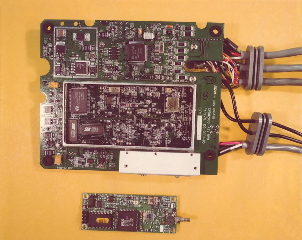
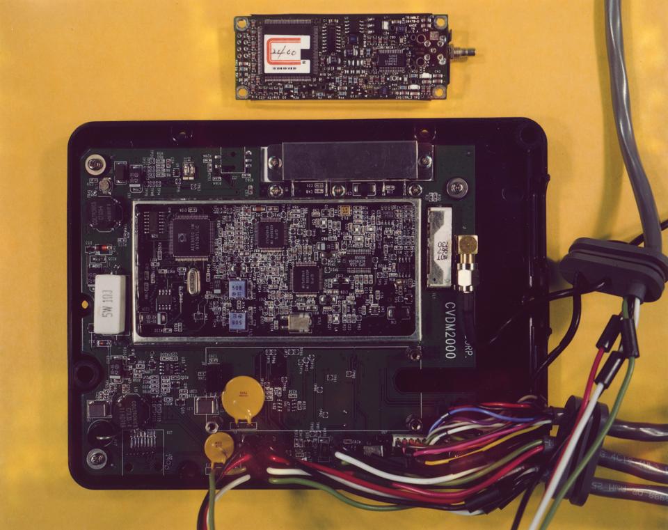
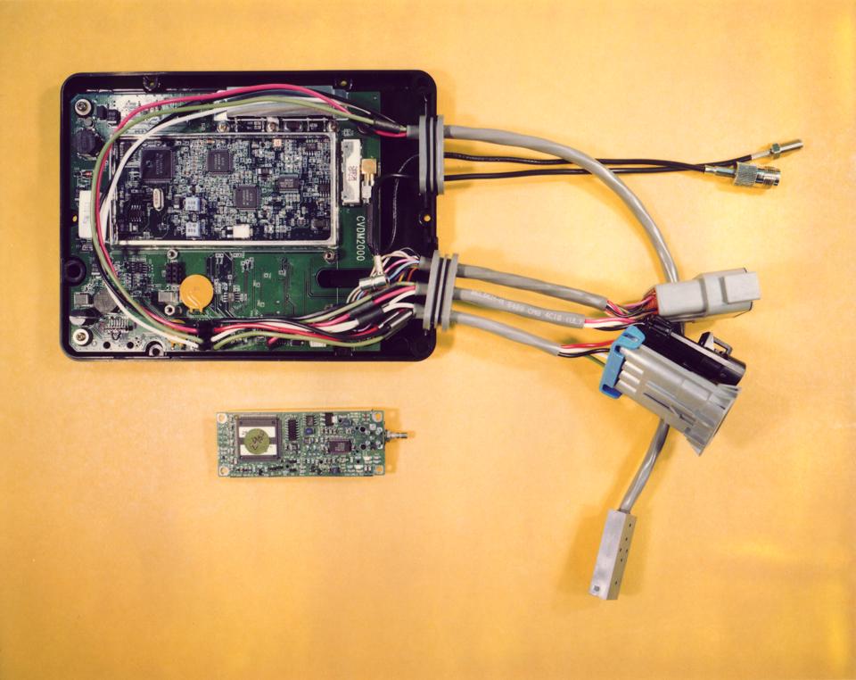
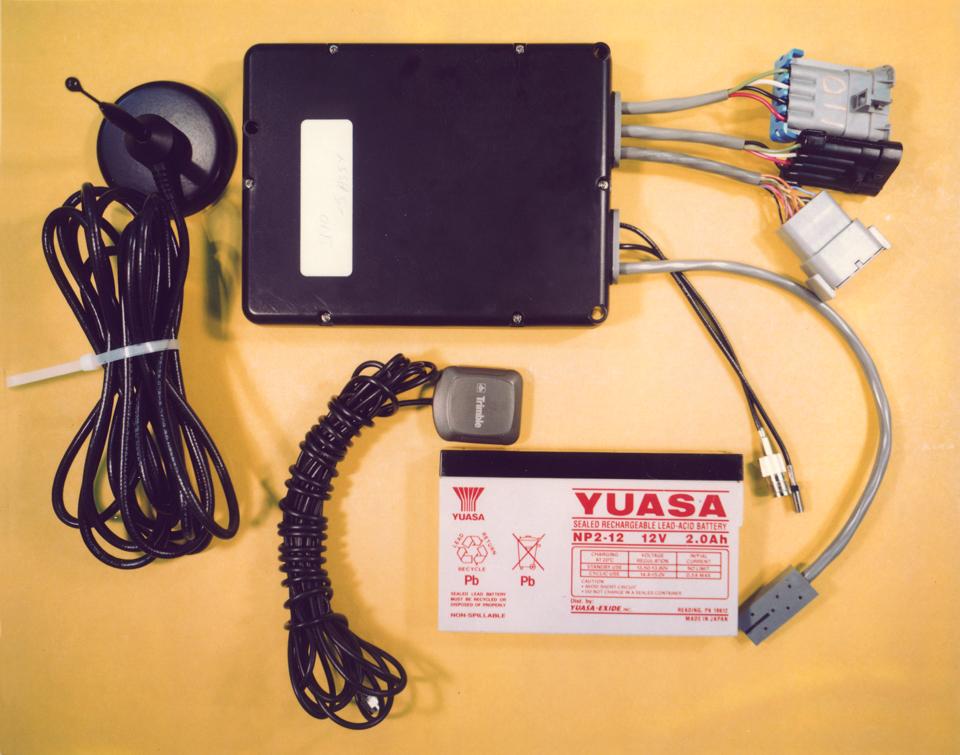
CELL-TRAC™ II FCC Type Acceptance7/13/01 FCC ID NMF-CT2-001Page 1 of 29 RAYTHEON TI SYSTEMS CELL-TRAC™ II FCC Type Acceptance FCC ID NMF-CT2-001 COPYRIGHT © 1998 RAYTHEON TI SYSTEMS ALL RIGHTS RESERVED CELL-TRAC™ II FCC Type Acceptance7/13/01 FCC ID NMF-CT2-001Page 2 of 29 Enclosed please find Raytheon TI’s submittal for FCC certification for the CELL- TRAC™ II cellular transceiver. This application mentions type acceptance throughout, but was compiled prior to the October 5, 1998, effective date changing the Commission’s equipment authorization process from type acceptance to certification. The enclosed application is made up of 11 exhibits, with individual exhibits containing more than a single file in many cases. The layout of the application is as follows: Exhibit 0 - this file (exhibit0.doc) that describes the product and measurements performed to show compliance with the Commission’s rules Exhibit 1 - contains six files: exhibit1.doc that describes the files that make up this exhibit, 4 picture files that show the construction and layout of the product (pic_1.jpg, pic_2.jpg, pic_3.jpg, pic_4.jpg) and a file showing the circuit layout of the product (exh_1.wp). Exhibit 2 - made up of a single file (exhibit2.doc) that shows the FCC label format and label locations. Exhibit 3 - consists of two files, exhibit3.doc which provides a detailed block diagram and theory of operation and ACE9040.pdf which is the manufacturer specification sheet for a particular chip used in the transceiver. Exhibit 4 - contains two files, exhibit4.doc and exhibit_4.pdf that provide circuit diagrams for the transceiver. Exhibit 5 - contains four files, exhibit5.doc, exh_5_a.doc, exh_5_b.doc, exh_5_c.doc that provide the testing and tune up procedures for the product. Exhibit 6 - contains a single file, exhibit6.doc, that describes ESN protection methods. Exhibit 7 - contains a single file, exhibit7.doc, that contains MPE data. Exhibit 8 - contains a single file, exhibit8.doc, the user manual. Exhibit 9 - contains two files, exhibit9.doc and Its.pdf, the test report. Confidentiality Request - is contained in file confid.doc. CELL-TRAC™ II FCC Type Acceptance7/13/01 FCC ID NMF-CT2-001Page 3 of 29 Table of Contents Section I Introduction ___________________________________________________ 5 Section II Summary of Application _________________________________________ 5 Section III Data ________________________________________________________ 5 2.981 Type Acceptance _________________________________________________________ 5 2.983 Application for Type Acceptance – Form 731 _________________________________ 7 2.983(a) Name of Applicant ___________________________________________________________ 7 2.983(b) Identification of the Equipment _________________________________________________ 7 2.983 (c) Production is Planned ________________________________________________________ 7 2.983 (d) Technical Description ________________________________________________________ 7 2.983 (d) -1 Types of Emission _____________________________________________________ 11 2.983 (d) -2 Frequency Range ______________________________________________________ 11 2.983 (d) -3 Range of Operating Power _______________________________________________ 12 2.983 (d) -4 Maximum Transmit Power level (22.913(a) 7 W ERP) _________________________ 12 2.983 (d) -5 DC Voltages and Current ________________________________________________ 12 2.983 (d) -6 Functions of each active circuit ___________________________________________ 12 2.983 (d) -7 Circuit Diagrams ______________________________________________________ 13 2.983 (d) -8 Users /Instruction Book _________________________________________________ 13 2.983 (d) – 9 Tune – up Procedure___________________________________________________ 13 2.983 (d) - 10 Frequency Stability ___________________________________________________ 13 2.983 (d) – 11 Circuits for Suppression of Spurs, Limiting Modulation, or Power Limits_________ 14 2.983 (d) - 12 Digital Modulation ___________________________________________________ 15 2.983 (e) Data _____________________________________________________________________ 15 2.983 (f) ID Plate __________________________________________________________________ 15 2.983 (g) Equipment Construction & Layout _____________________________________________ 15 2.985 -2.997 Measurements Required___________________________________________ 15 2.985(a) Measurements Required: RF Power Output ______________________________________ 16 22.913 Measurements Required: Effective Radiated Power ________________________________ 17 2.987 Measurements Required: RF Modulation __________________________________________ 17 22.915(a) Non-Voice Modulation signals _______________________________________________ 18 22.915(b) Modulating signals. ________________________________________________________ 18 22.915(c) Deviation Limitation Circuitry ________________________________________________ 19 22.915(d)(1) Measurements Required: Audio Filter Characteristics ___________________________ 20 2.989(c)(1) Measurements Required: Occupied Bandwidth, and 22.917(b)(d) Emission Limitations for Cellular __________________________________________________________________________ 21 22.917(b) Emission Limitations, F3E/F3D Emission Mask _______________________________ 22 22.917(d) Emission Limitations, F1D Emission Mask ___________________________________ 22 22.917(e) Measurements Required: Out of Band Emissions, and 22.917(f) Mobil Emissions in Base Frequency Range___________________________________________________________________ 23 22.917(e) Out of Band Emissions ___________________________________________________ 23 22.917(f) Mobil Emissions in Base Frequency Range ___________________________________ 24 2.993 Measurements Required: Field Strength of Spurious Radiation, 15.109(a) Radiated Emission Limits, and 22.917(e) Out of Band Emissions ____________________________________________ 24 15.109(a) Radiated Emission Limits …
Text truncated - open the document above for the full version.
RF Exposure Info
CELL-TRAC™ II FCC Type Acceptance7/13/01 FCC ID NMF-CT2-001Page 1 of 2 Exhibit 7 MPE Data Exhibit 7 contains the calculations showing that the CELL-TRAC™ II complies with the limits for maximum permissible exposure (MPE) per OET Bulletin 65. CELL-TRAC™ II FCC Type Acceptance7/13/01 FCC ID NMF-CT2-001Page 2 of 2 The maximum effective radiated power (ERP) was measured to be 36.5 dBm at the low channel see Exhibit 9 Intertek Testing Services NA Inc. Test Report.. 1.Convert ERP from dBm to milliwatts (mW): dBm = 10 LOG(Watts*1000) ERP(mW) = INV-LOG(36.5dBm/10) = 4467 mW 2.Equation 5 from OET Bulletin 65: S = EIRP = 1.64 ERP = 0.41 ERP (5) 4πR 2 4πR 2 πR 2 3.Using Equation 5 calculate power density level of exposure, S exp : S exp = (0.41 * 4467 mW) / (3.1416 * (20cm ) 2 ) = 1.46 mW/cm 2 4.The maximum permissible exposure (MPE) limit per OET Bulletin 65, Appendix A, Table 1B the Power Density (S) for General Population/Uncontrolled Exposure is: S limit = f/1500, f = frequency in MHz, fmax = 849 MHz S limit = 849/1500 = 0.566 mW/cm 2 5.The CELL-TRAC™ II can make up to one call every hour and the call will be for less than 5 minutes (30 seconds average), t exp . Using Equation 2 calculate the allowable time of exposure t exp , and the average power density level of exposure, S avg : S exp t exp = S limit t avg (2), for 1 to n calls in 30 minutes. Use n = 1. 1.46 mW/cm 2 * t exp = 0.566 mW/cm 2 * 30 minutes t exp = (0.566 mW/cm 2 * 30 minutes) / 1.46 mW/cm 2 = 11.6 minutes = t exp S avg = (1.46 mW/cm 2 * 5 minutes) / 30 minutes = 0.25 mW/cm 2 = S avg The average power density level of exposure, S avg = 0.25 mW/cm 2 , is less than the MPE limit, S limit = 0.566 mW/cm 2 , thus showing that the requirements of CFR 47 Part 2 Section 2.1091 were met.
RF Exposure Info
CELL-TRAC™ II FCC Type Acceptance7/9/01 FCC ID NMFPage 1 of 2 Exhibit 7 MPE Data Exhibit 7 contains the CELL-TRAC™ II maximum permissible exposure (MPE) data, calculations and warning label. CELL-TRAC™ II FCC Type Acceptance7/9/01 FCC ID NMFPage 2 of 2 The radiated emission of the unit with it’s antenna was measured. The maximum Corrected Reading was 133.9 dB(uV/m) at low channel. This value corresponds to a ERP of 36.5 dBm see Exhibit 9 Intertek Testing services NA Inc. Test Report page 5 and 5a. 1.Convert ERP from dBm to milliwatts (mW): dBm = 10 LOG(Watts*1000) ERP(mW) = INV-LOG(36.5dBm/10) = 4467 mW 2.The maximum permissible exposure (MPE) limit per OET Bulletin 65, Appendix A, Table 1B the Power Density (S) for General Population/Uncontrolled Exposure is: S limit = f/1500, f = frequency in MHz, fmax = 849 MHz S limit = 849/1500 = 0.566 mW/cm 2 3.Using Equation 5 from OET Bulletin 65 (and adding 3dB (ERP * 2) for reflection from a ground plane) calculate minimum distance to the center of radiation of the antenna: S = EIRP = 1.64 ERP = 0.41 ERP (5) 4πR 2 4πR 2 πR 2 R 2 = (0.41 * (ERP *2 ) ) / ( S limit * 3.1416 ) = 2060 cm 2 R = 45.4 cm minimum 4.The CELL-TRAC™ II is a box which is used with an antenna connected via a cable to its connector. It is not used as a handheld device to be held against one’s ear. The antenna is to be mounted at least 50 centimeters (20 inches) away from the body of the user or nearby persons. The following warning label will be mounted on all CELL-TRAC™ II units. Warning While this device is in operation, a separation distance of at least 50 centimeters (20 inches) should be maintained between the radiating antenna and the body of the user or nearby persons in order to meet the FCC RF exposure guidelines.
Test Report
Raytheon TI Systems Testing Performed on the Cellular Transceiver Model No.: CELL-TRAC TM II FCC Part 22 Type Acceptance Date of Test: August 17, 1998 & September 16, 1998 LTO# J98023875 Date of Report: September 17, 1998 Total No. of Pages Contained in this Report: 21 FCC Part 22 Type Acceptance Intertek Testing Services NA Inc. 1365 Adams Court, Menlo Park, CA 94025 Telephone 650-463-2900 Fax 650-463-2910 Home Page www.worldlab.com All services undertaken are subject to the following general policy: Reports are submitted for exclusive use of the client to whom they are addressed. Their significance is subject to the adequacy and representative character of the samples and to the comprehensiveness of the tests, examinations or surveys made. No quotations from reports or use of Intertek Testing Servicesís name is permitted except as expressly authorized by Intertek Testing Services in writing. i Intertek Testing Services VERIFICATION OF COMPLIANCE Report No. J98023875 . Equipment Under Test (EUT):Cellular Transceiver Trade Name:Raytheon TI Systems Model No.:CELL-TRAC TM II Serial No.:Not Labelled FCC ID: Applicant:Raytheon TI Systems Contact:Ron Cleveland/Curt Larsen Address:13532 N. Central Expwy. Dallas, Texas 75243 Mail Stop 64 Tel. number:(972) 344-4350 Fax. number:(972) 344-3504 Applicable Regulation:FCC Part 22 Type Acceptance SAR Exposure Class:N/A Test Site Location:Intertek Testing Services 1365 Adams Court Menlo Park, CA 94025, USA Date of Test:August 17, 1998 & September 16, 1998 Verification is hereby issued to the named APPLICANT and is VALID ONLY for the equipment tested hereon for use under the rules and regulations listed below Based on the test results, the tested sample was found to be in compliance with FCC Part 22 requirements. We attest to the accuracy of this report: Intertek Testing Services Intertek Testing Services NA Inc. 1365 Adams Court, Menlo Park, CA 94025 Telephone 650-463-2900 Fax 650-463-2910 Home Page www.worldlab.com ii INTERTEK TESTING SERVICES Raytheon TI Systems, Cellular TransceiverDate of Test: Aug. 17, 1998 & Sept. 16, 1998 Report number: J98023875 Table of Contents 1.0Test Summary ....................................................................................................................1 1.2 Product Description................................................................................................. 2 2.0RF Power Output................................................................................................................3 2.1 Test Procedure......................................................................................................... 3 2.2 Test Equipment........................................................................................................ 3 2.3 Test Results.............................................................................................................. 3 3.0Effective Radiated Power ..................................................................................................5 3.1 Test Procedure......................................................................................................... 5 3.2 Test Equipment........................................................................................................ 5 3.3 Test Results.............................................................................................................. 5 4.0Modulation Deviation Limiting .........................................................................................6 4.1 Test Procedure......................................................................................................... 6 4.2 Test Equipment........................................................................................................ 6 4.3 Test Results.............................................................................................................. 6 5.0Audio Filter Characteristics ..............................................................................................9 5.1 Test Procedure......................................…
Text truncated - open the document above for the full version.
Contact Information
Applicant
Earl D. Munns(Counsel)
Technical Contact
Raytheon TI Systems IncRonald W Cleveland
[email protected]972-344-4350
13532 N. Central Expressway, M.S. 64 · Dallas, Texas · United States
Non-Technical Contact
Raytheon TI Systems IncBruce Anderson
[email protected]972-344-3480
Test Firm
Intertek Testing Services NA Inc.John Quigley
Technical Specifications
| # | Rule Parts | Frequency Range | Power Output | Emission | Tolerance |
|---|---|---|---|---|---|
| 3 | 22.901(d) | 824.04 MHz - 849 MHz | 3 W | 28K0G1D | 2.5 ppm |
Other Applications from Raytheon Company dba Raytheon Systems Co.
NMFAAGSM19500M
Apr 04, 19992 Channel Amplifier/Antenna
Equipment Class
PCB - PCS Licensed TransmitterNMFAAGS1912501C1B
Feb 02, 1998Single Channel Amplifier/Antenna Approved for use with PCS-1900 emissions (GXW).
Equipment Class
PCB - PCS Licensed Transmitter