NN4RGW2400-ODDirect Sequence Spread Spectrum Transceiver
Root Inc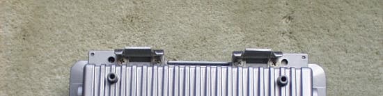
Click to zoom
Application Details
- Equipment Class
- DTS - Digital Transmission System
- Date of Grant
- Jul 24, 2002
- Application Purpose
- Original Equipment
- Date of Application
- Jul 24, 2002
- Equipment Note
- Direct Sequence Spread Spectrum Transceiver
- Frequency Range
- 2432.00000000 - 2447.00000000
- Company
- Root Inc
- Country
- Japan
Documents & Files
Document Text
Text extracted from the exhibit documents filed with the FCC. Open a document above to read the original.
Users Manual
Z990002-D08-12 Instruction Manual RGW2400/OD U.S.A. 2 FCC Notice This equipment has been tested and found to comply with the limits for a Class B digital device, pursuant to Part 15 of the FCC Rules. These limits are designed to provide reasonable protection against harmful interference in a residential installation. This equipment generates, uses, and can radiate radio frequency energy and, if not installed and used in accordance with the instructions, may cause harmful interference to radio communications. However, there is no guarantee that interference will not occur in a particular installation. If this equipment does cause harmful interference, the user is encouraged to try to correct the interference by one or more of the following measures: •Reselect or relocate the antenna. •Increase the separation between the equipment and receiver. •Consult the dealer or an experienced radio technician for help. Changes or modifications not expressly approved in writing by ROOT Inc. may void the user’s authority to operate this equipment. ROOT Inc. can not accept any financial or other responsibilities that may be the result of your use of this information, including direct, indirect, special, or consequential damages. 3 Handling precautions Strictly observe the following important handling precautions when using the product: W W ARNING ARNING Indicates that user's mishandling of the product may lead to a danger resulting in a serious injury or death. CAUTION CAUTION Indicates that user's mishandling of the product may lead to a danger resulting in an injury or a physical damage alone. l WARNING Working at high place to install the main unit and antenna may result in an injury or death due to a fall. Do not work in an unstable position or shaky footing and be sure to ensure the safety before starting work. l WARNING Do not put up the antennal in a thunderstorm, on a windy day or in a cold season, otherwise you may be struck by lightning or may be subject to other danger. l WARNING When installing the main unit and antenna, firmly fix them in accordance with the installation manual. If they are insufficiently fixed, they may drop, causing an injury or death. l WARNING The main unit and AC adaptor get hot extremely, causing a burn or injury. Carefully handle them, when it is necessary to touch them, as they generate heat, place them in a well-ventilated location. l WARNING Do not use them in abnormal conditions where smoke or offensive smell is coming out, otherwise causing a fire, electric shock or trouble. l CAUTION When installing or removing each unit, be sure to turn off power supply beforehand. If it is installed or removed with power turned on, a trouble may occur. l CAUTION Never disassemble the equipment, otherwise causing a trouble. l CAUTION Do not drop the product and do not give a strong shock to it, otherwise causing a trouble. l CAUTION Never open the main unit. l CAUTION 4 Do not use it near a television or radio. Do not install it near a television antenna etc., otherwise causing an electromagnetic interference, equipment trouble and communication error. l CAUTION Do not use it near anything that consumes large electric power and generates noise or strong radio waves (microwave oven etc.), otherwise resulting in equipment trouble or communication error. 5 Table of contents 1 System Configurations6 2 Name of Each Part7 3 Installing Main Unit9 3.1 Mount the Main Unit..............................................................................................9 3.2 Installing the Interface Cable................................................................................10 4 Antenna Selection13 4.3 Antenna List.........................................................................................................13 4.4 Cable List..............................................................................................................13 5 Specifications14 6 For More Help15 6 1 System Configurations RGW2400/OD is a separate type radio router that can be installed outdoor. It consists of the following components: RGW2400/OD OD main unit Junction unit (HUB with built-in 4 ports) AC Adapter IF cables (10m/20m) Antennal cable 10/100BASE-T HUB Antenna 7 2 Name of Each Part BLUE WHITE 11Mbit/sec Model:RGW2400/OD 2.4GHzSpreadSpectrum ResidentiaiGatewaySystem RealObjectOrientedTechnologies ROOTINC. No.00001 2.4DS4 1 23 RGW2400/OD_ Main Unit (1)Antenna Terminal Connect the antenna._After completion of connection, finish with self-melting adhesive tape for waterproofing. (2)Interface-Cable Connector 2 Connect the interface cable with a blue cap. 8 (3)Interface-Cable Connector 1 Connect the interface cable with a white cap. Pass the interface cable. Connect the cable to the inside connector and then fit the cable clamp. After completion of setting, finish with self-melting adhesive tape for waterproofing. FDX/Col Main Radio RunTxRxLink RGW2400/OD ROOTINC. Main Up3 2 1 Link/Act 123Uplink Link/Act100 CONSOLEI/F2 I/F1 GND BLUEWHITE DCIN 1415 1716181920 456 7891011 1213 RGW2400/OD Junction Unit (4)FDX/Col Lamp Indicates the state of each port of the hub. It is on, while the main unit is connected by full duplex. It blinks when a collision occurs. (5)Uplink Port FDX/Col Lamp It is the FDX/Col lamp of Uplink port of the hub and has the same contents of display as other ports. (6)Main Unit FDX/Col Lamp It is the FDW/Col lamp between the main unit and hub and has the same contents of other ports. (7)Radio LINK Lamp When a radio packet is received, this lamp turns on. When radio-related setting is changed, it turns off. (8)Radio RX Lamp While receiving a radio packet, this lamp is on. (9)Radio TX Lamp While transmitting a radio packet, this lamp is on. (10)RUN Lamp When this unit is turned on and initializing is completed, this lamp is on. (11)Main Unit Link/Act Lamp When a link is established between the main unit and hub, this lamp is on. This lamp also functions as Active indicator. (12)Link/…
Text truncated - open the document above for the full version.
Users Manual
Z0105001-L00-01 RGW series Setup manual For Version 1.4.1 ROOT Inc. 1. Setup Method 1.1 Connections First, it is required to login in order to set up this unit. There are two methods to login; one is through serial line, and two, through telnet or Secure Shell (SSH) from a host on LAN. When setting up with serial line, we suggest using terminal software such as Hyperterminal for personal computers. Setup configurations for terminal software are as follows: Data Transfer Rate: 19200 bps Character Bit Length: 8 Parity Check: None Stop Bit Length: 1 Flow Control: RGW 2400/OD - hardware flowflIsn’t it “None”?, as Japanese manual says To connect with SSH, prior setup by serial line or telnet is required. Refer to "Generating Host key of SSH" (Section 1.7.50). 1.2 Setup There are two methods for setup: One is to use command-line shell by command input from console; the other is to directly rewrite configuration file from internal OS shell. Setup through internal OS shell requires knowledge of both OS and network. Please contact us regarding specific setup method. 1.3 User Mode and Privileged Mode The command-line shell has two modes which are privileged mode and user mode. Mode Description Prompt Privileged Mode A mode that can execute all commands "$" User Mode A mode that can execute only basic commands and display commands ">" 1.4 Setting by Command Line Shell A login prompt is displayed when connected with telnet: login: Enter user name "admin": login: admin<CR> Proceed to enter password: Password:xxxxxxxx<CR> (Note: Entered password is not displayed. See Section 3 for factory default user mode password setting.) When login is accomplished, prompt > is displayed. When changing the setup, it is required to move to privileged mode. To move to privileged mode, enter command: >administrator<CR> Proceed to enter password for privileged mode: password:xxxxxxxx<CR> (Note: Entered password is not displayed. See Section 3 for factory default privileged mode password setting.) Prompt $ is displayed. To connect with SSH, please refer to "Generating Host key of SSH" (Section 1.7.50). 1.4.1 List of Command Line Shell Functions Function Description Supplement to Command By pressing [TAB] key, command string is inserted to the supplemental part possible Help on Commands By pressing [?] key, displays list of available command or description of each command. Example: $ip? *ip address *ip route add *ip route delete Since no command is formed in ip, commands starting with ip are displayed. $ ip address ? usage: ip address"Interface Ipaddress Netmask" e.g. : $ ip address ep0 192.168.0.100 255.255.255.0 Since the command "ip address" is unique, usage and examples are displayed. Editing Command Line This function supports editing of command line. The key bind of each is as follows: Key Description Back Space Deletes one character before cursor Ctrl-A Moves cursor to the head of command line Ctrl-E Moves cursor to the end of command line Ctrl-D Deletes the character on cursor Ctrl-U Deletes the entire command line Ctrl-F (->) Moves cursor to the right Ctrl-B (<-) Moves cursor to the left Ctrl-K Deletes the character after cursor Record of Entered Commands Retains records of inputted command Key Description Ctrl-P Calls previous recorded entry Ctrl-N Calls next recorded entry 1.5 List of Commands Setup Item Command Setting password passwd Setting host name hostname Setting IP address ip address Setting static route ip route add Deleting static route ip route delete Setting ICMP Redirect send out ip icmp redirect Setting wireless frequency wireless channel Setting wireless transmission rate wireless tx rate Setting wireless WEP function wireless wep encryption Setting wireless WEP key number wireless wep key use Setting wireless WEP key value wireless wep key value Setting wireless port type wireless port Setting wireless network name wireless network Setting wireless station name wireless station Switching infrastructure mode to Access Point wireless BSS AP mode Setting wireless SSID wireless ssid Adding wireless MAC address filter wireless macfilter add Deleting wireless MAC address filter wireless macfilter delete Setting static ARP entry arp add Deleting ARP entry arp delete Setting to choose the use of RIP rip Setting to choose to send static route with rip rip static-supply Setting RIP action rip action Setting RIP version rip version Setting to choose the use of filter filter Setting Filter filter add Deleting Filter filter delete Setting to choose the use of NAT nat Setting map action of NAT nat add map Setting bimap action of nat nat add bimap Setting map-block action of nat nat add map-block Setting rdr action of nat nat add rdr Deleting nat nat delete Setting to choose the use of DHCP server dhcp Setting IP address to be distributed by DHCP server dhcp pool Setting validity period of IP address to be distributed by DHCP server dhcp expire Setting DNS server to be distributed by DHCP server dhcp dns add Deleting DNS server to be distributed by DHCP server dhcp dns delete Setting domain name to be distributed by DHCP server dhcp domain Setting default route to be distributed by DHCP server dhcp defaultroute Setting DHCP relay agent dhcp relay Setting to choose the use of SNMP function snmp Setting SNMP community name snmp community Setting location of SNMP snmp location Setting contact of SNMP snmp contact Setting access of SNMP snmp access Setting TRAP of SNMP snmp trap Setting of syslog syslog Setting of host to transfer syslog syslog host Setting facility to transfer syslog syslog add Deleting facility to transfer syslog syslog delete Generating SSH host key ssh keygen Setting SSH authenticate method ssh authentication Downloading SSH public key ssh keyget Setting telnet access access telnet Setting monitor access access monitor Setting ssh access access ssh Save save Loading setting contents load Cold start cold start Updating firmware update Setting date and time date Displaying software version show…
Text truncated - open the document above for the full version.
Users Manual
Answer ID 1048 Product PRISM Wireless PRISM 1 (11Mbps) Category Access Points Date Created 02/14/2001 11:55 AM Date Updated 04/13/2001 04:08 PM Print Answer E-mail Answer Power output for the United States. Question Regarding the bridge. What is the power output for the United States limited at? 18dBm? Answer The United States (FCC regulation domain) has a fixed output power of 18 dBm. How well did this answer your question? 100%75%50%25%0% Submit Rating Related Answers • HIP6004, PGOOD Be used for a second HIP6004 SS pin. • Power down/Power Save timing questions. • What is offered for Notebook CPU Power, System Power and Battery Management ICs? • HS1-26CT31RH, Power supplies pin open. • CD40109BMS Voltage level shifter. • More related answers... Close Window 7/18/02 10:14 AMAnswer Page 1 of 1http://www.intersil.com/rnwscripts/custfaq.cfg/php.exe/enduser/popup_adp.php?p_sid=ZWhWRskg&p_lva=&p_li=&p_faqid=1048&p_created=982169733
Cover Letter(s)
tel: 650-726-1263 fax: 650-726-1252 [email protected] Thomas N. Cokenias EMC &Radio Approvals Test & Consulting Services for Commercial, Military, International Compliance P.O. Box 1086 El Granada, CA 94018 FCC Laboratory16 July 2002 7435 Oakland Mills Road Columbia, MD 21046 Attention: Application Examiner Reviewing Engineer Applicant: Root Inc. FCC ID: NN4RGW2400-OD To whom it may concern, Request is hereby submitted, on behalf of my client Root Inc. to withhold from public review certain portions of the application for equipment certification for the referenced FCC identifier. In particular, the following sections of the application and report are requested to be kept confidential: Block Diagrams Schematic Operational Description Rationale for request for confidentiality: Root Inc. has invested considerable time and materials in research and development to produce the referenced product. Disclosure of the confidential portions of this application to competitors would give them competitive advantage in developing similar products. If you have questions or need further information, please contact the undersigned. Sincerely, tel: 650-726-1263 fax: 650-726-1252 [email protected] THOMAS N. COKENIAS EMC Consultant/Agent for Root Inc.
Cover Letter(s)
From: Tom Cokenias [[email protected]] Sent: Thursday, July 18, 2002 11:51 AM To: Mike Kuo Subject: Re: FW: Root Inc, FCC ID:NN4RGW2400-OD, AN02T2108 Hello Mike, Answers follow questions. best regards Tom >-----Original Message----- >From: CERTADM >Sent: Wednesday, July 17, 2002 3:39 PM >To: '[email protected]' >Subject: Root Inc, FCC ID:NN4RGW2400-OD, AN02T2108 > > >Notice_content > ------------- >Question #1: The frequency range indicated on the TCB application form is >from 2432 - 2447 MHz. This frequency range has been repeated in the test >report as well. However, the minimum 6dB BW listed and measured with >frequency range from 2412-2472MHz, RF output power listed and measured with >frequency range from 2412-2472MHz, Conducted spurious emission listed and >measured with frequency range from 2412-2472MHz, Power Spectral Density >measured with 2412 and 2443 MHz only. > >Please review the test report named " Supercede " and provide any necessary >corrections. ANS #1 I have corrected and submitted the test report to show 2412 - 2472 MHz coverage. This product can be used with a variety of antennas, the ones currently being certified will be limited to the range 2432 - 2447 MHz due to gain at the bandedge. Other antennas will be added in the future (by class 2 pc) which will be useable at other channels. >Question #2: There are four separation radiated bandedge measurements were >made and submitted as separate attachments. One of file named " Directional >15dBi" contains failing data. Please review your data. ANS#2 The Directional 15 dBi is a preliminary data file and was sent to you in error. The radiated bandedge emissions are in the body of the test report. I have submitted a new file to the website HIGHfreq 15 dBi Antenna.xls, which contains radiated data to 10th harmonic for the 15 dBi directional antenna. > >Question #3: Please provide radiated spurious emission data to 10th >harmonics for Directional antenna with 15dBi gain. ANS#3 Done, see answer 2. > >Question #4: Do you want to certify this device under DTS or Spread Spectrum >transmitter ? Please know, the new docket for DTS will only be effective >after July 25, 2002. ANS#4 Please certify this product as DTS. Please let me know by return when you will issue grant for this application, if you are satisfied with the answers presented here > >Question #5: Please provide MPE estimate result. ANS#5 Confirmation indicates successful upload of RGW2400 OD MPE.pdf which is the mpe information. I will upload it again. > >Question #6: There is no RF exposure warning statement in the user manual, >Please provide revise user manual to comply this requirement. ANS#6 I have uploaded modified user manual with the required statement. > >Question #7: This question is related to Question #1, the user manual >indicate the TX range is from 2412- 2462 with max. output of 10mW/MHz. >Please make sure the technical specification contains in the user manual >agree with the measurement result. ANS#7 User manual has been corrected to show 2412-2472 MHz coverage. Test report has been corrected for frequency range, see ANS#1. Intersil which makes the PRISM chipset used with this product says design power output is 18 dBm, with variation. I have uploaded pdf files Power distribution.pdf and US power out.pdf from Intersil supporting this. Their numbers are consistent with a maximum 10 dBm/MHz power density. Best regards Tom > >Best Regards > >Mike Kuo / TCB Certifier >The items indicated above must be submitted before processing can continue >on the above referenced application. Failure to provide the requested >information within 60 days of the original e-mail date may result in >application dismissal and forfeiture of the filing fee. Also, please note >that partial responses increase processing time and should not be submitted. >Any questions about the content of this correspondence should be directed to >the e-mail address listed below the name of the sender.
ID Label/Location Info
FCC Label/Location FCC ID: NN4RGW2400-OD This device complies with Part 15 of the FCC Rules. Operation is subject to the following two conditions: (1) This device may not cause harmful interference, and (2) This device must accept any interference received, including interference than may cause undesired operation Bottom view
Internal Photos
Photographs of Board Top view bottom view MIRAE TECHNOLOGY FCC ID: O6ANANOSPEED EXHIBIT #: 3B
Parts List/Tune Up Info
view cart Clickto Purchasethe NEW 3Com WirelessAccess Point2000 ListPrice $ OurPrice 229.00 $189.00 about uswireless networking solutionsiDEN productstwo-way radiosradio accessoriestrunking systems Maxrad MFB24010 Technical Specifications ManufacturerMaxrad, Inc TableMFB24010 TESSCO Part No.25421 Drawing Specific Freq. (MHz)2400-2483 Gain (dBd)7.9 Maximum Input Power (Watts) 25 Watts TypeFiberglass Omni Product Narrative Omnidirectional ISM base antenna is designed to cover whole band at 1.5:1 VSWR. No need for a ground plane,can be mounted in variety of locations. Bandwidth (MHz)100 Gain (dBi)10 H. BeamwidthOmni Vert. BeamwidthN/A Front to Back Ratio (dB) N/A VSWR1.5:1 PolarizationVertical Lightning Prot.N/A Overall Size36" long Weight.65 Lbs. Rated Wind Velocity (MPH) 125 MPH Wind Load, (sq ft)0.17 sq.ft. Lateral Thrust @ RWV (lbs) 15.4 Lbs. Bending Moment @ RWV (ft lbs) 22.6 ft-Lbs. TerminationN Female Jumper IncludedN/A Mounting StylePole or wall Clickto Purchasethe NEW 3Com WirelessAccess Point2000 ListPrice $ OurPrice 229.00 $189.00 about uswireless networking solutionsiDEN productstwo-way radiosradio accessoriestrunking systems 7/16/02 10:31 AMMaxrad MFB24010 Spec Sheet Page 1 of 2http://www.teamonecomm.com/store/NSG/MFB24010_Specs.htm Send mail towith questions orcomments about this web site. Copyright © Team One Communications, Inc. Last modified: June 08, 2002. | [email protected] 2001 Privacy StatementTerms UPS Package Tracking Mount Hdw. Incl.None, MMK1924 Sold Sep Warranty2 Years Qty/Uom1 EACH List ($)275.00 Send mail towith questions orcomments about this web site. Copyright © Team One Communications, Inc. Last modified: June 08, 2002. | [email protected] 2001 Privacy StatementTerms UPS 7/16/02 10:31 AMMaxrad MFB24010 Spec Sheet Page 2 of 2http://www.teamonecomm.com/store/NSG/MFB24010_Specs.htm
Parts List/Tune Up Info
B A C K 15 An ISO-9001 Registered Company The MAXRAD XtremeWave™ sector panel covers the 2.4 GHz ISM band and pro- vides field adjustable horizontal beamwidths of 45º, 60º, 90º or 120º. This unique design allows a system installer to stock a single antenna and field adjust it to the desired beamwidth, making it useful for wireless broadband applications where coverage of a geographical sector is desired. The panel can also be ordered with fixed beamwidths. This line also includes a compact 90° sector model for applications where space is very limited. This fixed beamwidth antenna measures less than 8 inches long. In many applications, sector panels are used to provide omnidirectional cover- age by using, for example, three radios and three 120º sector antennas to pro- vide 360º coverage. This results in a stronger and more focused signal than that of a single omnidirectional antenna. It also provides a more robust design. The antenna features industry leading front-to-back ratios of more than 42 dB at 45º, 60º and 90º and over 32 dB at 120º with excellent cross pole discrimination. Feature and Benefits • Adjustable multiple beamwidth sectors. A single antenna can be utilized to cover several geographical sectors. • Three sectors with three data radios can be installed as an array for omnidi- rectional coverage. Provides a stronger, more focused signal than that of a standard omnidirectional antenna. • Industry leading front-to-back ratios. Ensures that the radiated energy is focused towards its target, and not to the back or sides of the antenna. General Specifications: 2.4 GHz sector panel antennas Radome Material: Off white ASA plastic with UV resistance Termination: Type N, female. Other connector options available Polarization: Vertical Lighting Protection: DC grounded Mounting Method: Adjustable stainless steel bracket, +/- 11 degrees of uptilt or downtilt Pipe diameter: 0.75 thru 2.4” OD (19-60 mm) Nominal Impedance: 50 Ohms 2.4 GHz ISM Adjustable Sector Panel Antenna XtremeWave™ MSP24013MB The MSP24013MB allows horizontal beamwidth adjustments without having to replace the antenna. Its patented design is one of the most compact currently available on the market. Sector Panel on adjustable bracket Mechanical Specifications Electrical Specifications Model # Rated Wind Velocity Horizontal Thrust at Rated Wind Temperature RangeDimensionsWeight MSP24013MB 125 mph 200 km/h 43 lb 19.5 kg -22°F to 167°F -30°C to +75°C 21.5" L x 6.5" W x 2.8" D 546 mm L x 16.5 mm W x 7.2 mm D 4 lbs 1.8 kg MSP24013-120 MSP24014-90 MSP24016-60 MSP24017-45 MSP2401090PT 125 mph 200 km/h 43 lb 19.5 kg -30°C to +75°C 8.0" L x 6.5" W x 2.8" D 203 mm L x 16.5 mm W x 7.2 mm D 3 lbs 1.3 kg Model # Frequency Range Nominal Gain Front-to- Back Ratio Horizontal Plane Beamwidth E-Plane Beamwidth Typical Cross Poll Discrimination VSWR Max. Power Input MSP24013MB 2400-2500 MHz 13 dBi at 120° 14 dBi at 90° 16 dBi at 60° 17 dBi at 45° > 32 dB at 120° > 42 dB at 90° > 42 dB at 60° > 42 dB at 45° 120°, 90°, 60° and 45° 16° 270°-0°, 0°-90° = -20 dB 235°-270°, 90°-135° = -28 dB 180°-235°, 135°-180° = -32 dB < 1.5:1 50 W MSP24013-120 2400-2500 MHz 13 dBi> 32 dB120°16° 270°-0°, 0°-90° = -20 dB 235°-270°, 90°-135° = -28 dB 180°-235°, 135°-180° = -32 dB < 1.5:1 50 W MSP24014-90 2400-2500 MHz 14 dBi> 42 dB90°16°< 1.5:1 50 W MSP24016-60 2400-2500 MHz 16 dBi> 42 dB60°16°< 1.5:1 50 W MSP24017-45 2400-2500 MHz 17 dBi> 42 dB45°16°< 1.5:1 50 W MSP2401090PT 2400-2486 MHz 10 dBi> 32 dB90°35° >20 dB< 1.5:1 50 W ORDER (800) 323-9122 FAX (630) 372-8077 www.maxrad.com Specs and Patterns Elevation Beamwidth 45°, 60°, 90° and 120° Sectors An ISO-9001 Registered Company 17 Patterns 120° Azimuth Cut 90° Azimuth Cut 60° Azimuth Cut 45° Azimuth Cut ORDER (800) 323-9122 FAX (630) 372-8077 www.maxrad.com Patterns MSP2401090 Elevation Cut MSP2401090 Azimuth Cut
Parts List/Tune Up Info
B A C K 25 An ISO-9001 Registered Company MP24008XFPT or MP19008XFPT or MP58013XFPT MP24013XFPT on MPAB12 Corner Mount MP58013XFPT or MP24008XFPT or MP19008XFPT on MPAB11 Mount MP24013XFPT on MPAB8 Outdoor Mount MP24018XFPT XtremeWave™ MPXF Series General Specifications: Directional panel antennas Radome Material: UL 94-V0 plastic Polarization: Linear, Vertical/Horizontal. Left hand circular (MP24012CPLXF only). Nominal Impedance: 50 Ohms Mounting Method: The MAXRAD XtremeWave™ directional panel antennas are designed to cover PCS, 2.4 GHz and 5.8 GHz frequencies with a VSWR of less than 1.5:1, obtaining maximum gain with an attractive, low-profile package. All models provide effi- cient and stable performance across the band and can be mounted indoors or outdoors. Features and Benefits: •Patented printed circuit board design. Best performance-to-price ratio. •UL94-V0 plastic and PC board. Provides UL’s highest flame retardant rating allowing maximum placement flexibility. Meets the most stringent building fire rating codes. •Attractive, low profile housing. Blends well with indoor and outdoor environ- ments where aesthetic considerations are important. •Corner exit RG-58/U pigtail design. Permits the linear polarized panel to be mounted in vertical or horizontal polarity with a wide variety of connectors. •Optional UL 910 rated Plenum cable. Allows the cable to be installed in the strictest indoor mounting locations, including air ducts. •Adjustable mounting brackets for indoor and outdoor mounting. Provide maximum flexibility for indoor or outdoor installations. Model / MountMPAB7MPAB8MPAB10 MPAB11 MPAB12 MP19008XFPTN/AN/AN/Aincluded optional MP19013XFPToptionaloptionalN/Aoptional optional MP24008XFPTN/AN/AN/Aincluded optional MP24012CPLXFPToptionaloptionalN/Aoptional optional MP24013XFFPToptionaloptionalN/Aoptional optional MP24018XFPToptionaloptionaloptionalN/AN/A MP58013XFPTN/AN/AN/Aincluded optional Mount Description Heavy duty outdoor adjustable mount with +/-35° uptilt/downtilt. If used with MP24018XFPT, the mount provides +/-18° uptilt/downtilt. Same as MPAB8, but bracket is longer. Heavy duty outdoor adjustable mount with 17° uptilt/downtilt. If used with MP24018XFPT, the mount provides +/-9° uptilt/downtilt. Heavy duty outdoor adjustable mount +/-20° uptilt/downtilt and +/-90° polarity. Includes DSS satellite style house bracket. Short adjustable indoor mount. It may be used outdoors with small housing panels only. Long adjustable indoor corner mount. PCS, 2.4 GHz ISM and 5.8 GHz ISM Directional Panel Antenna Series Model # Wind Loading (Frontal) @100 mph Wind Temperature RangeDimensionsWeightCable MP19008XFPT 9.3 lbs. -40°C to +80°C 5.1" x 4.7" x 1.5" (12.9 x 11.9 x 3.8 cm) 0.5 lbs (0.23 kg) 12" (30.5 cm) RG58/U* MP19013XFPT 27.9 lbs. -40°C to +80°C 8.8" x 8.1" x 1.6" (22.4 x 20.6 x 4.06 cm) 1.2 lbs (0.54 kg) 12" (30.5 cm) RG58/U* MP24008XFPT 9.3 lbs. -40°C to +80°C 5.1" x 4.7" x 1.5" (12.9 x 11.9 x 3.8 cm) 0.5 lbs (0.23 kg) 12" (30.5 cm) RG58/U* MP24012CPLXFPT 27.9 lbs. -40°C to +80°C 8.8" x 8.1" x 1.6" (22.4 x 20.6 x 4.06 cm) 1.2 lbs (0.54 kg) 12" (30.5 cm) RG58/U* MP24013XFPT 27.9 lbs. -40°C to +80°C 8.8" x 8.1" x 1.6" (22.4 x 20.6 x 4.06 cm) 1.2 lbs (0.54 kg) 12" (30.5 cm) RG58/U* MP24018XFPT 85 lbs. -40°C to +80°C 15.1 x 13.9 x 1.9 in (38.4 x 35.3 x 4.8 cm) 3.9 lbs (1.8 kg) 12" (30.5 cm) RG58/U* MP58013XFPT 9.3 lbs. -40°C to +80°C 5.1" x 4.7" x 1.5" (12.9 x 11.9 x 3.8 cm) 0.5 lbs (0.23 kg) 6" (15.25 cm) RG58/U Model # Frequency Range Gain Front-to- Back Ratio 3 dB Horizontal Beamwidth 3 dB Vertical Beamwidth VSWR Maximum Power Input Connector Options MP19008XFPT 1850 - 1990 MHz 8.0 dBi > 15 dB90°60° < 1.5:1 20 W N, female (part #NF) is standard. Other connector options are available. Please consult factory for details. MP19013XFPT 1850 - 1990 MHz 12.5 dBi > 18 dB40°35° < 1.5:1 20 W MP24008XFPT 2300 - 2500 MHz 8.5 dBi > 15 dB60°60° < 1.5:1 20 W MP24012CPLXFPT 2300 - 2500 MHz 12.0 dBic > 20 dB35°35° < 1.5:1 20 W MP24013XFPT 2300 - 2500 MHz 13.0 dBi > 18 dB35°35° < 1.5:1 20 W MP24018XFPT 2300 - 2500 MHz 18.0 dBi > 25 dB18°19° < 1.5:1 20 W MP58013XFPT 5725 - 5875 MHz 12.5 dBi > 23 dB42°28° < 1.5:1 20 W ORDER (800) 323-9122 FAX (630) 372-8077 www.maxrad.com Mechanical Specifications Electrical Specifications Specs and Patterns MP19008XFPT Elevation Cut MP19013XFPT Elevation Cut MP19013XFPT Azimuth Cut MP19008XFPT Azimuth Cut 27 An ISO-9001 Registered Company ORDER (800) 323-9122 FAX (630) 372-8077 www.maxrad.com Patterns MP24008XFPT Elevation Cut MP24008XFPT Azimuth Cut MP24013XFPT Azimuth Cut MP24012CPLXFPT Elevation Cut MP24012CPLXFPT Azimuth Cut MP24013XFPT Elevation Cut ORDER (800) 323-9122 FAX (630) 372-8077 www.maxrad.com Patterns MP24018XFPT Elevation Cut MP58013XFPT Azimuth Cut MP240018XFPT Azimuth Cut MP58013XFPT Elevation Cut
RF Exposure Info
Sheet1 Root Inc. FCC ID: NN4RGW2400-OD RF Hazard Distance Calculation mW/cm2 from Table1:1.00 Max RF PowerTX AntennaMPE P, dBmG, dBiSafe Distance, cm 17.88.05.5patch 17.810.06.9omni 17.813.09.8sector 17.815.012.3directional Basis of Calculations: E^2/3770 = S, mW/cm2 E, V/m = (Pwatts*Ggain*30)^.5/d, meters d = ((Pwatts*G*30)/3770*S))^0.5Pwatts*Ggain = 10^(PdBm-30+GdBi)/10) NOTE: For mobile or fixed location transmitters, minimum separation distance is 20 cm, even if calculations indicate MPE distance is less Page 1
Test Report
1 EMISSIONS TEST REPORT FOR A LOW POWER TRANSMITTER I. GENERAL INFORMATION Requirement:Federal Communications Commissions Test Requirements: 15.205, 15.207, 15.209, 15.247 Applicant:Root Inc. 2F, KS Bldg., 1-17-8 Nishikata Bunkyo-ku, Tokyo 113-0024, JAPAN FCC ID: NN4RGW2400-0D II. DESCRIPTION OF EQUIPMENT UNDER TEST (EUT) The RGW2400-OD is a …
Text truncated - open the document above for the full version.
Contact Information
Applicant
Toshihisa Yamada(Manager)
Test Firm
Compliance Certification Services IncSteve Cheng
Technical Specifications
| # | Rule Parts | Frequency Range | Power Output |
|---|---|---|---|
| 1 | 15C | 2.43 GHz - 2.45 GHz | 60.00 mW |
Other Applications from Root Inc
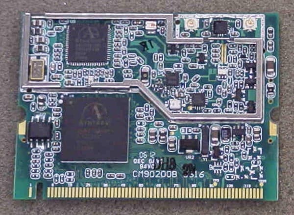
NN4RZ2009
Jul 20, 2006802.11b/g WIRELESS LAN
Equipment Class
DTS - Digital Transmission SystemNN4RZ95000
Feb 02, 1998Data link transmitter module Maximum output power: 50mW.
Equipment Class
DSS - Part 15 Spread Spectrum Transmitter