NN4RZ2009802.11b/g WIRELESS LAN
Root Inc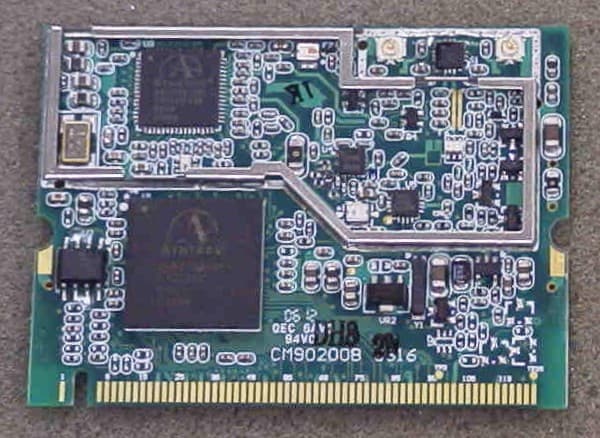
Click to zoom
Application Details
- Equipment Class
- DTS - Digital Transmission System
- Date of Grant
- Jul 20, 2006
- Application Purpose
- Original Equipment
- Date of Application
- Jul 20, 2006
- Equipment Note
- 802.11b/g WIRELESS LAN
- Frequency Range
- 2412.00000000 - 2462.00000000
- Company
- Root Inc
- Country
- Japan
Documents & Files
Document Text
Text extracted from the exhibit documents filed with the FCC. Open a document above to read the original.
Users Manual
WLAN a+b+g mini-PCI Module RZ2009 User Manual Version: 1.0 March 2004 1 Copyright Statement No part of this publication may be reproduced, stored in a retrieval system, or transmitted in any form or by any means, whether electronic, mechanical, photocopying, recording or otherwise without the prior writing of the publisher. Windows ™ 98SE/2000/ME/XP are trademarks of Microsoft ® Corp. Pentium is trademark of Intel. All copyright reserved. 2 Federal Communication Commission Interference Statement This equipment has been tested and found to comply with the limits for a Class B digital device, pursuant to Part 15 of the FCC Rules. These limits are designed to provide reasonable protection against harmful interference in a residential installation. This equipment generates, uses and can radiate radio frequency energy and, if not installed and used in accordance with he instructions, may cause harmful interference to radio communications. However, there is no guarantee that interference will not occur in a particular installation. If this equipment does cause harmful interference to radio or television reception, which can be determined by turning the equipment off and on, the user is encouraged to try to correct the interference by one of the following measures: - Reorient or relocate the receiving antenna. - Increase the separation between the equipment and receiver. - Connect the equipment into an outlet on a circuit different from that to which the receiver is connected. - Consult the dealer or an experienced radio/TV technician for help. FCC Caution: To assure continued compliance, (example - use only shielded interface cables when connecting to computer or peripheral devices) any changes or modifications not expressly approved by the party responsible for compliance could void the user's authority to operate this equipment. This device complies with Part 15 of the FCC Rules. Operation is subject to the following two conditions: (1) This device may not cause harmful interference, and (2) This device must accept any interference received, including interference that may cause undesired operation. IMPORTANT NOTE: The device shall not be used in such a manner that the potential for human contact during normal operation is minimized. It is the responsibility of the installer and users of the device to guarantee that the antenna operates at least 20 centimeters (8 inches) from any person. The antenna should not be co-located with any other antenna or transmitter. This is necessary to insure that the product operates in accordance with the FCC RF Guidelines for Human Exposure Labeling Considerations 3 The OEM product that employs FCC ID: NN4RZ2009 RF module shall label as below: “Contains transmitter module FCC ID: NN4RZ2009” or “Contains FCC ID: NN4RZ2009” Professional Installment The device must be installed by professionals in accordance with responsible party’s instruction manual. Modification Modifications to the device, unless expressly approved by the responsible party, could void the user’s authority to operate the device. Antenna Type The device uses a 26 dBi parabolic grid antenna with a specified length of coax cable. . 4 Table of Contents 1. INTRODUCTION 5 2. DRIVER/UTILITY INSTALLATION / UNINSTALLATION 6 2.1 I NSTALLATION.........................................................................................................6 2.2 A DDITIONAL S ETUP P ROCESSES ..............................................................................9 2.3 U NINSTALLATION...................................................................................................10 3. CONNECTING TO AN EXISTING NETWORK 11 4. CREATING AN AD HOC NEW NETWORK 16 5. MODIFYING A WIRELESS NETWORK 19 5.1 I NFRASTRUCTURE MODE AND AD HOC MODE.....................................................19 5.2 M ODIFYING A WIRELESS NETWORK.....................................................................20 5.3 D EFAULT SETTINGS WINDOWS XP ZERO-CONFIGURATION................................27 5.4 S UPER A/G S ETTING ..............................................................................................27 APPENDIX A: FAQ ABOUT WLAN 28 APPENDIX B: SPECIFICATION 30 5 1. Introduction Thank you for purchasing the WLAN a+b+g mini-PCI Module that provides the easiest way to wireless networking. This User Manual contains detailed instructions in the operation of this product. Please keep this manual for future reference. System Requirements z A laptop PC contains: - 32 MB memory or greater - 300 MHz processor or higher z Microsoft ® Win ™ 2000/ME/98 Second Edition/XP 6 2. Driver/Utility Installation / Uninstallation 2.1 Installation Note! The Installation Section in this User Manual describes the first-time installation for Windows. To re-install the driver, please first uninstall the previously installed driver. See Chapter 2.3 “Uninstallation” in this User Manual. Follow the steps below to complete the driver/utility installation: 1. Insert the Installation Software CD into the CD-Rom Drive. 2. Click “Next” . 3. Read the License Agreement and click “Yes”. 7 4. Click “Next” to continue or click “Browse” to choose a destination folder. 5. Click “Next”. 6. Click “Yes” to create a shortcut icon on your desktop. 8 7. Click “Finish” . 8. You should now see a shortcut icon on your desktop. 9 2.2 Additional Setup Processes During software installation procedure, each operating system may prompt different specific options: 1. Windows 98SE: The system will request the original Windows CD during the installation process. When the installation is finished, you’ll have to restart your computer. 2. Windows Me: Please restart your computer when the installation is finished. 3. Windows 2000/XP: Select “Install the software automatically” when the window with this option appears, and then click “Next” to continue installation. 10 2.3 Uninstallation Note! Before uninstallation, please close all running programs. 1. Click Start>Programs>WLAN a…
Text truncated - open the document above for the full version.
Cover Letter(s)
ROOT Inc. 232 Minami Otsuka Toshima-ku Tokyo 170 Federal Communications Commission Authorization and Evaluation Division Subject: Confidentiality Request regarding application for certification of FCC ID: NN4RZ2009 Dear Madam or Sir: Pursuant to Sections 0.457 and 0.459 of the Commission’s Rules, we hereby request confidential treatment of information accompanying this application as outlined below: • Schematics • Block diagram • Circuit Description • Antenna Specification The above materials contain trade secrets and proprietary information not customarily released to the public. The public disclosure of these materials may be harmful to the applicant and provide unjustified benefits to its competitors. The applicant understands that pursuant to Section 0.457 of the Rules, disclosure of this application and all accompanying documentation will not be made before the date of the Grant for this application. Pursuant to DA 04-1705 June 15, 2004 of the Commission’s public notice, we also request temporary confidential treatment of information accompanying this application as outlined below: • External Photos • Internal Photos • Test Setup Photos • User’s Manual Sincerely, Mitz Hase On behalf of ROOT Inc.
Cover Letter(s)
ROOT Inc. 232 Minami Otsuka Toshima-ku Tokyo 170 Federal Communications Commission Authorization and Evaluation Division Subject: Confidentiality Request regarding application for certification of FCC ID: NN4RZ2009 Dear Madam or Sir: The 802.11a mentioned in the block diagram, circuit description , and user’s manual is not applicable to the miniPCI card, FCC ID: NN4RZ2009. Sincerely, Mitz Hase On behalf of ROOT Inc.
Cover Letter(s)
ROOT Inc. 232 Minami Otsuka Toshima-ku Tokyo 170 Federal Communications Commission Authorization and Evaluation Division Subject: Request for a Modular Approval – FCC ID: NN4RZ2009 Dear Madam or Sir: ROOT Inc. is seeking for FCC authorization for the use of its 802.11b/g miniPCI card as a modular transmitter. The requirements of the FCC Public Notice DA00-1407 is met. The following requirements are fulfilled: 1. The modular transmitter must have its own RF shielding. The radio portion of the module is contained in its own RF shielding. See submitted photos. 2. The modular transmitter must have buffered modulation/data inputs The modulation/data inputs are buffered. 3. The modular transmitter must have its own power supply regulation The modular transmitter has its own PS regulation. 4. The modular transmitter must be labeled with its own FCC ID number The DUT is labeled with its own FCC ID number. The label is specified in related exhibit. If the module is installed inside of an end-point, the label is not visible. In that case, the user will be instructed how to apply exterior label. 5. The modular transmitter must comply with any specific rule or operating requirements applicable to the transmitter and the manufacture must provide adequate instruction along with the module to explain any such requirements. The DUT complies with all applicable FCC rules per test report. Detailed instructions are given in the user’s guide. 6. The modular transmitter must comply with any applicable RF exposure requirements. The DUT complies with RF exposure requirements. The details are enclosed in the user’s manual. Sincerely, Mitz Hase On behalf of ROOT Inc.
ID Label/Location Info
RZ2009 Label Document 1. Module Label FCC Label FCC Label FCC ID : NN4RZ2009
Test Report
FCC PART 15.247 DIRECT SEQUENCE TEST REPORT APPLICANT ROOT INC. ADDRESS 8F 2nd TOC BUILDING 7-21-11 NISHI-GOTANDA, SHINAGAWA-KU TOKYO JAPAN FCC ID NN4RZ2009 MODEL NUMBER N/A PRODUCT DESCRIPTION 802.11b/g mini PCI card DATE SAMPLE RECEIVED July 17, 2006 DATE TESTED July 17, 2006 TESTED BY Nam Nguyen APPROVED BY Mario de Aranzeta C.E.T. TIMCO REPORT NO. 2118AJT6TestReport TEST RESULTS PASS FAIL THE ATTACHED REPORT SHALL NOT BE REPRODUCED EXCEPT IN FULL WITHOUT THE WRITTEN APPROVAL OF TIMCO ENGINEERING, INC. 849 NW STATE ROAD 45 NEWBERRY, FL 32669 USA PH: 888.472.2424 OR 352.472.5500 FAX: 352.472.2030 EMAIL: [email protected] HTTP: //WWW.TIMCOENGR.COM Certificate # 0955-01 Certificate # 0955-01 APPLICANT: ROOT Inc. FCC ID: NN4RZ2009 REPORT: V:\R\ROOT\2118AJT6\2118AJT6TestReport.doc Page 2 of 24 TABLE OF CONTENTS STATEMENT OF COMPLIANCE.................................................................................. 3 GENERAL INFORMATION .......................................................................................... 4 EMC EQUIPMENT LIST ............................................................................................. 5 TEST PROCEDURE ................................................................................................... 6 POWER LINE CONDUCTED INTERFERENCE............................................................. 7 6.0dB BANDWIDTH ................................................................................................. 10 POWER OUTPUT ..................................................................................................... 12 SPURIOUS EMISSIONS AT ANTENNA TERMINALS .................................................. 13 FIELD STRENGTH OF SPURIOUS EMISSIONS......................................................... 14 RADIATED SPURIOUS EMISSIONS INTO ADJACENT RESTRICTED BAND............... 17 POWER SPECTRAL DENSITY................................................................................... 22 RF EXPOSURE REQUIREMENT ............................................................................... 24 Certificate # 0955-01 APPLICANT: ROOT Inc. FCC ID: NN4RZ2009 REPORT: V:\R\ROOT\2118AJT6\2118AJT6TestReport.doc Page 3 of 24 STATEMENT OF COMPLIANCE This equipment has been tested in accordance with the standards identified in the referenced test report. To the best of my knowledge and belief, these tests were performed using the measurement procedures described in this report and demonstrate that the equipment complies with the appropriate standards. I attest that the necessary measurements were made by me or under my supervision, at Timco Engineering, Inc. located at 849 N.W. State Road 45, Newberry, Florida 32669 USA. Authorized by: Mario de Aranzeta Signature: Function: Engineer Date: July 19, 2006 Tested by: Nam Nguyen Signature: on file Date: July 17, 2006 Certificate # 0955-01 APPLICANT: ROOT Inc. FCC ID: NN4RZ2009 REPORT: V:\R\ROOT\2118AJT6\2118AJT6TestReport.doc Page 4 of 24 GENERAL INFORMATION Test Report Purpose: The test report is to show the compliance of tested article with FCC Part 15.247 modular approval requirement. Test Results: The test results relate only to the items tested. Test Article: FCC ID: NN4RZ2009 Model Number: RZ2009 Serial Number: N/A Product Description: 802.11b/g mini PCI card Operating Frequency: 2412 - 2462 GHz Max. output power (conducted): mode 11b: 13 dBm; mode 11g: 18.2 dBm Type of Modulation: CCK and OFDM Primary Power 110VAC/50-60Hz Power Supply: Secondary Power 3.3 Vdc for module Test Item: Pre-Production Type of Equipment: Mobile Antenna Type: 26 dBi Parabolic antenna, m/n: AT373 Antenna Connector: Standard connector (‘N’ type) Professional installation required Modification to the EUT: none Description of certified system: The system consists of a mini PCI module and the following antenna system: 16 meters of 5D2V coaxial cable and a 26 dBi parabolic reflector antenna. The test platform (host) was the applicants AT-TQ5528 router system. Test Facilities: All measurements were made at one or more of the test sites of TIMCO ENGINEERING INC. located at 849 N.W. State Road 45, Newberry, FL 32669. Test Exercise (e.g software description, test signal, etc.): The EUT was set in continuous transmit mode of operation. Test Conditions: All the tests were preformed at a temperature of 78°F and a relative humidity of 55%. Test Standards: ANSI C63.4: 2003, FCC Part 15.247 Certificate # 0955-01 APPLICANT: ROOT Inc. FCC ID: NN4RZ2009 REPORT: V:\R\ROOT\2118AJT6\2118AJT6TestReport.doc Page 5 of 24 EMC EQUIPMENT LIST Device Manufacturer Model Serial Number Cal/Char Date Due Date 3/10-Meter OATS TEI N/A N/A Listed 3/27/04 3/26/07 3-Meter OATS TEI N/A N/A Listed 1/11/06 1/10/09 Biconnical Antenna Eaton 94455-1 1057 CAL 12/12/05 12/12/07 Biconnical Antenna Eaton 94455-1 1096 CAL 8/17/04 8/17/06 Biconnical Antenna Electro-Metrics BIA-25 1171 CAL 4/29/05 4/29/07 Analyzer Tan Tower Preamplifier HP 8449B-H02 3008A00372 CAL 12/8/05 12/8/07 Analyzer Tan Tower Quasi-Peak Adapter HP 85650A 3303A01690 CAL 12/8/05 12/8/07 Analyzer Tan Tower RF Preselector HP 85685A 3221A01400 CAL 12/7/05 12/7/07 Analyzer Tan Tower Spectrum Analyzer HP 8566B Opt 462 3138A07786 3144A20661 CAL 12/7/05 12/7/07 LISN Electro-Metrics ANS-25/2 2604 CAL 8/27/04 8/27/06 LISN Electro-Metrics EM-7820 2682 CAL 4/28/05 4/28/07 Log-Periodic Antenna Eaton 96005 1243 CAL 12/14/05 12/14/07 Certificate # 0955-01 APPLICANT: ROOT Inc. FCC ID: NN4RZ2009 REPORT: V:\R\ROOT\2118AJT6\2118AJT6TestReport.doc Page 6 of 24 TEST PROCEDURE Power Line Conducted Interference: The procedure used was ANSI STANDARD C63.4- 2003 using a 50uH LISN. The spectrum was scanned from .15 to 30 MHz. The bandwidth of the spectrum analyzer was 10 kHz with an appropriate sweep speed. Bandwidth 6 dB: The measurements were made with the spectrum analyzer's resolution bandwidth (RBW) = 100kHz and the video bandwidth (VBW) = 3 MHz and the span set as shown on plot. Power Output: The RF power outpu…
Text truncated - open the document above for the full version.
Contact Information
Applicant
Toshihisa Yamada(Manager)
Test Firm
Timco Engineering, Inc.Sid Sanders
Technical Specifications
| # | Rule Parts | Frequency Range | Power Output |
|---|---|---|---|
| 1 | 15C | 2.41 GHz - 2.46 GHz | 66.00 mW |
Other Applications from Root Inc

NN4RGW2400-OD
Jul 24, 2002Direct Sequence Spread Spectrum Transceiver
Equipment Class
DTS - Digital Transmission SystemNN4RZ95000
Feb 02, 1998Data link transmitter module Maximum output power: 50mW.
Equipment Class
DSS - Part 15 Spread Spectrum Transmitter