NNT1005Reflex Telemetry Device, OMNIDATA
PerComm Inc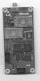
Click to zoom
Application Details
- Equipment Class
- PCB - PCS Licensed Transmitter
- Date of Grant
- Dec 05, 2002
- Application Purpose
- Original Equipment
- Date of Application
- Sep 02, 2002
- Equipment Note
- Reflex Telemetry Device, OMNIDATA
- Frequency Range
- 901.00000000 - 902.00000000
- Company
- PerComm Inc
- Country
- United States
Documents & Files
Document Text
Text extracted from the exhibit documents filed with the FCC. Open a document above to read the original.
Users Manual
Document Number: 9420.00005-USRGD, Revision: 1.1, July 24, 2002; User’s Guide for the PerComm OMNIDATA Telemetry Device – PT1005A (DRAFT) Copyright 2002, PerComm, Inc. All rights reserved. Document Number: 9420.00005-USRGD Revision 1.1 7/24/2002 Document Change Record July 24, 2002 • Version 1.1 • Minor edits after first review. July 18, 2002 • Version 1.0 • Initial version. 7/24/02 User’s Guide for the PerComm OMNIDATA Telemetry Device– PT1005A (DRAFT) ii Document Number: 9420.00005-USRGD Revision 1.1 7/24/2002 Table of Contents 1 INTRODUCTION............................................................................................................................................1 1.1 Document Identification............................................................................................................................1 1.2 Document Overview..................................................................................................................................1 1.3 Contact Information...................................................................................................................................1 1.4 Copyrights and Trademarks.....................................................................................................................1 1.5 Safety............................................................................................................................................................2 1.6 References....................................................................................................................................................2 2 OMNIDATA OVERVIEW..............................................................................................................................3 2.1 Introduction.................................................................................................................................................3 2.2 Physical Features........................................................................................................................................3 2.3 Over-The-Air Interface...............................................................................................................................3 2.4 ReFLEX 2.7.1.1 Protocol Stack...................................................................................................................4 2.5 Host Interface..............................................................................................................................................4 2.6 FLEXsuite Encoder.....................................................................................................................................4 2.7 Configurable Database...............................................................................................................................4 2.8 Embedded Software...................................................................................................................................4 2.9 Power Input.................................................................................................................................................4 3 SPECIFICATIONS...........................................................................................................................................5 3.1 Introduction.................................................................................................................................................5 3.2 Product Specification.................................................................................................................................5 3.3 Connector Specifications...........................................................................................................................6 3.4 Power Supply Requirements....................................................................................................................7 3.5 Mechanical Specifications..........................................................................................................................7 4 INSTALLATION AND OPERATION....................................................................................................... 10 4.1 Introduction...............................................................................................................................................10 4.2 Installation Procedure..............................................................................................................................10 4.3 Power-On Procedure................................................................................................................................11 4.4 External Antenna Guidelines..................................................................................................................11 7/24/02 User’s Guide for the PerComm OMNIDATA Telemetry Device– PT1005A (DRAFT) iii Document Number: 9420.00005-USRGD Revision 1.1 7/24/2002 1 INTRODUCTION 1.1 Document Identification “User’s Guide for the PerComm OMNIDATA Telemetry Device – PT1005A”, Document Number 9420.00005-USRGD. 1.2 Document Overview This document is intended for a technical audience installing or operating the PerComm OMNIDATA Telemetry Device (model number PT1005A). This document is organized as follows: • Chapter 1 provides an overview of this User’s Guide. • Chapter 2 provides an overview of the OMNIDATA device. • Chapter 3 provides the technical specifications of the OMNIDATA device. • Chapter 4 provides procedures and guidelines for the installation and operation of the OMNIDATA device. This document has been carefully reviewed for accuracy. However, no responsibility is assumed for any inaccuracies. The information in this document and the products described in this document are subject to change without notice. 1.3 Contact Information Any questions or comments regarding this manual or the PerComm OMNIDATA Telemetry Device …
Text truncated - open the document above for the full version.
Users Manual
Document Number: 9400.01484-USG01, Revision: 1.6, December 2, 2002; User's Guide for the PerComm OMNIDATA Telemetry Device - PT1005A (DRAFT) Copyright 2002, PerComm, Inc. All rights reserved. Document Number: 9400.01484-USG01 Revision 1.6 12/2/2002 Document Change Record July 18, 2002 – December 02, 2002 • Version 1.0 – 1.6 • Preliminary (draft) revisions. 12/2/02 User's Guide for the PerComm OMNIDATA Telemetry Device - PT1005A (DRAFT) ii Document Number: 9400.01484-USG01 Revision 1.6 12/2/2002 Table of Contents 1 INTRODUCTION............................................................................................................................................1 1.1 Document Identification............................................................................................................................1 1.2 Document Overview..................................................................................................................................1 1.3 Contact Information...................................................................................................................................1 1.4 Copyrights and Trademarks.....................................................................................................................1 1.5 Safety and Limitations...............................................................................................................................2 1.6 RF Exposure Information..........................................................................................................................2 1.7 References....................................................................................................................................................3 2 OMNIDATA OVERVIEW..............................................................................................................................4 2.1 Introduction.................................................................................................................................................4 2.2 Physical Features........................................................................................................................................4 2.3 Over-The-Air Interface...............................................................................................................................5 2.4 ReFLEX 2.7.1.1 Protocol Stack...................................................................................................................5 2.5 Host Interface..............................................................................................................................................5 2.6 FLEXsuite Encoder.....................................................................................................................................5 2.7 Configurable Database...............................................................................................................................5 2.8 Embedded Software...................................................................................................................................6 2.9 Power Input.................................................................................................................................................6 3 SPECIFICATIONS...........................................................................................................................................7 3.1 Introduction.................................................................................................................................................7 3.2 Product Specification.................................................................................................................................7 3.3 Connector Specifications...........................................................................................................................8 3.4 Power Supply Requirements....................................................................................................................9 3.5 Mechanical Specifications..........................................................................................................................9 4 INSTALLATION AND OPERATION....................................................................................................... 11 4.1 Introduction...............................................................................................................................................11 4.2 Installation Setting....................................................................................................................................11 4.3 Installation Procedure..............................................................................................................................11 4.4 Power-On Procedure................................................................................................................................12 4.5 External Antenna Impedance.................................................................................................................13 12/2/02 User's Guide for the PerComm OMNIDATA Telemetry Device - PT1005A (DRAFT) iii Document Number: 9400.01484-USG01 Revision 1.6 12/2/2002 1 INTRODUCTION 1.1 Document Identification “User's Guide for the PerComm OMNIDATA Telemetry Device - PT1005A (DRAFT)”, Document Number 9400.01484-USG01. 1.2 Document Overview This document is intended for a technical audience installing or operating the PerComm OMNIDATA Telemetry Device (model number PT1005A). This document is organized as follows: • Chapter 1 provides an overview of this User’s Guide. • Chapter 2 provides an overview of the OMNIDATA device. • Chapter 3 provides the technical specifications of the OMNIDATA device. • Chapter 4 provides procedures and guidelines for the installation and operation of the OMNIDATA device. This document has been carefully reviewed for accuracy. Ho…
Text truncated - open the document above for the full version.
Cover Letter(s)
0; i;i) 0 ,:);!) 0 , 22 Tower Office Park , ;J cijJ i;;)", Woburn, Massachusetts 01801 USA ;;) ;;;) o;~;;~~ \;11!i~\ ,,1!",,1, @ Tel: 781-860-7700 .Fax: 781-860-0618 i;~ &ii' ;it; !jJfi Bilu~ .; UWii www.percomm.com -" -- July 30, 2002 Federal Communications Commission 7435 Oakland Mills Road Columbia, MD 21046 USA Urug Compliance Statement We the undersigned, hereby certify that no party to the applicant is subject to a denial of federal benefit pursuant to section 5301 of the Anti-Drug Abuse Act of 1988,21 USC 853a. Sincerely, By: -~~ ~- -S i gnature-U Dated this July 30, 2002 Edmond K. Fung President and CEO Telephone: + 1 (781) 860- 7700 Applicant: PerComm Inc.
Cover Letter(s)
"' ~ ~ ~ i4i)", Corporate Office "", -*4) 'ij;, " ,i4i) WbM22AToo1w8eor1?2ffi1'1G3e UPaSrAk WJ:!Jw,U"'laJ' "" ujl'liJJJ o urn, Telephone: +1 781-860-7700 Fax: +1 781-860-0618 July 25, 2002 Federal Communications Commission 7435 Oakland Mills Road Columbia, MD 21046 USA Confidentiality of Material Reguest This letter is to comply with Section 0.457(d)(2)(i) pertaining to confidential material. Percomm, Inc. would like the following documents regarding this submission for FCC ID: NNT1005 to be kept confidential. 1. Schematics -7 files 2000-02633sdOxc.pdf 2. Design Overview -1 file The above material contains trade secrets or technical data, which would customarily be guarded from competitors. We do not want these documents to be accessible to the general public. Sincerely, Dated this July 25, 2002 ~Radu Oprea By: .ature Printed Senior RF Engineer Telephone: 604-293-5217 Applicant: Percomm, Inc.
External Photos
Corporate Office 22 Tower Office Park Woburn, MA 01801-2113 USA Telephone: +1 781-860-7700 Fax: +1 781-860-0618 EXTERNAL PHOTOS OF THE REFLEX TELEMETRY DEVICE, OMNIDATA, MODEL PT1005-A FCC PART 2.1033(c)(12) DATE OF ISSUE: SEPTEMBER 12, 2002 Photos OMNIDATA, PT1005-A The OMNIDATA is sold as an OEM product without housing. As such the external photos are the same as the internal ones. Bottom view of OMNIDATA device Photos OMNIDATA, PT1005-A Top view of OMNIDATA device
External Photos
Corporate Office 22 Tower Office Park Woburn, MA 01801-2113 USA Telephone: +1 781-860-7700 Fax: +1 781-860-0618 EXTERNAL PHOTOS OF THE REFLEX TELEMETRY DEVICE, OMNIDATA, MODEL PT1005-A FCC PART 2.1033(c)(12) DATE OF ISSUE: NOVEMBER 1, 2002 Photos OMNIDATA, PT1005-A Bottom view of OMNIDATA device Photos OMNIDATA, PT1005-A Top view of OMNIDATA device
ID Label/Location Info
Corporate Office 22 Tower Office Park Woburn, MA 01801-2113 USA Telephone: +1 781-860-7700 Fax: +1 781-860-0618 LABEL DRAWING OF THE REFLEX TELEMETRY DEVICE, OMNIDATA, MODEL PT1005-A FCC PART 2.1033(c)(11) DATE OF ISSUE: AUGUST 14, 2002 Label ID OMNIDATA, PT1005-A FCC ID Marking is done in silkscreen on the topside of the PCB.
Internal Photos
Corporate Office 22 Tower Office Park Woburn, MA 01801-2113 USA Telephone: +1 781-860-7700 Fax: +1 781-860-0618 PHOTOS OF THE REFLEX TELEMETRY DEVICE, OMNIDATA, MODEL PT1005-A FCC PART 2.1033(c)(12) DATE OF ISSUE: AUGUST 14, 2002 Photos OMNIDATA, PT1005-A Bottom view of OMNIDATA device Photos OMNIDATA, PT1005-A Top view of OMNIDATA device
Parts List/Tune Up Info
Corporate Office 22 Tower Office Park Woburn, MA 01801-2113 USA Telephone: +1 781-860-7700 Fax: +1 781-860-0618 PART LIST AND TUNE-UP PROCEDURE FOR REFLEX TELEMETRY DEVICE, OMNIDATA, MODEL PT1005-A FCC PART 2.1033(c)(9) & (10) DATE OF ISSUE: SEPTEMBER 12, 2002 Part List OMNIDATA, PT1005-A Part List of Active Devices and Resonators Schematic Ref. Designator Device Type Circuit Application Source Q1 Dual N-FET Switch FAIRCHILD SEMICONDUCTOR Q2 P-FET Power Switch SILICONIX INCORPORATED Q3 Dual NPN Buffer ON SEMICONDUCTOR Q4 Dual PFET Switch FAIRCHILD SEMICONDUCTOR Q5 Dual P-FET Switch FAIRCHILD SEMICONDUCTOR Q6 Dual NPN IF VCO NEC U1 CMOS IC Logic Gate FAIRCHILD SEMICONDUCTOR U2 CMOS IC Logic Gate FAIRCHILD SEMICONDUCTOR U3 CMOS IC Logic Gate FAIRCHILD SEMICONDUCTOR U4 CMOS IC SRAM CYPRESS SEMICONDUCTOR U5 CMOS IC Gate Array ATMEL U6 CMOS IC ROM SILCON STORAGE TECHNOLOGY U7 CMOS IC DSP TEXAS INSTRUMENTS INC. U8 BICMOS IC PLL Synthesizer NATIONAL SEMICONDUCTOR U9 Module VCO DELTA U10 BICMOS IC CODEC ANALOG DEVICES U11 Ga As IC Power Amplifier M/A-COM U12 BICMOS IC Operational Amplifier NATIONAL SEMICONDUCTOR U13 Bipolar IC Buffer NEC U14 Bipolar IC Modulator INFINEON U15 Bipolar IC Low Noise Amplifier INFINEON U17 Ga As IC RF Mixer INFINEON U18 Bipolar IC Demodulator ANALOG DEVICES U19 BICMOS IC Voltage Regulator NATIONAL SEMICONDUCTOR U20 Bipolar IC Temp. Sensor NATIONAL SEMICONDUCTOR U21 Module VCTCXO RAKON LTD U22 BICMOS IC Voltage Regulator NATIONAL SEMICONDUCTOR U23 Bipolar IC Power on Reset ON SEMICONDUCTOR U24 CMOS IC Voltage Regulator TELCOM SEMICONDUCTOR U25 Bipolar IC Voltage Regulator NATIONAL SEMICONDUCTOR Y1 Crystal 32.768 KHZ FOX ELECTRONICS INC Y2 Crystal 11.0592MHZ FOX ELECTRONICS INC Tune Up There is no tune-up procedure for OMNIDATA device.
RF Exposure Info
Corporate Office 22 Tower Office Park Woburn, MA 01801-2113 USA Telephone: +1 781-860-7700 Fax: +1 781-860-0618 PERCOMM RESPONSE TO FCC EMAIL FROM OCTOBER 21,2002 CORRESPONDENCE REFERENCE NUMBER: 24191 731 CONFIRMATION NUMBER: EA215226 REFLEX TELEMETRY DEVICE, OMNIDATA, MODEL PT1005-A DATE OF ISSUE: NOVEMBER 5,2002 PREPARED BY: Radu Oprea Percomm, Inc. 1570 Kootenay St. Vancouver, BC, V5K 5B8 Canada This document contains a total of 5 pages. Page 1 of 5 Percomm Response OMNIDATA, PT1005-A 1.) Please remove all shielding from printed circuit boards in the external photo exhibit. A new file with external photos with all shields removed has been uploaded. 2.) What is the maximum antenna gain that is used for this device. The device is sold without an antenna and PerComm is recommending a half wave dipole to be used with the device. As such the maximum gain is 0 dBd or 2.2dBi. 3.) Please submit an MPE evaluation. OMNIDATA is marketed and sold for use in “fixed locations” as this is defined in $2.1091 (b) and as such MPE limits should not apply to it. Nonetheless we provide an MPE calculation. The MPE evaluation is done making the following assumptions: OMNIDATA transmits at the maximum rated power of Pout =1 Watt, the antenna is a half dipole having the maximum gain of 2.2dBi, the transmitter duty cycle is the worst-case allowed under the ReFLEX protocol, the power density limits are for general population/ uncontrolled exposure. The worst-case duty cycle for the OMNIDATA device transmitter occurs on a collapse rate of 1 when the device is sending messages to the infrastructure. For this calculation, we assume infinite messages are queued in the device; each message is the maximum length allowed (700 bytes) and the back channel is running at its slowest speed (800 bps). The ReFLEX protocol is timed on frames, each being 1.875 seconds long. The sequence for transmitting a message from the device is shown in the following table. Also shown is transmitter on time and elapsed time in seconds. Frame Event Transmitter on-time Elapsed time 1 Device sends Request to Transmit to system 0.162 1.875 2 Request goes to system controller and is scheduled 0 1.875 3 Unusable Frame 0 1.875 4 Grant for data unit is sent to Device 0 1.875 5 Device sends first data unit (100 Bytes) to system 1.875 1.875 6 Data unit goes to system controller and next data unit is scheduled 0 1.875 7 Unused frame 0 1.875 Page 2 of 5 Percomm Response OMNIDATA, PT1005-A 8 Grant for next data unit is sent to Device 0 1.875 9 Device sends data unit to system 1.875 1.875 10 – 29 Repeat steps 6-9 until entire message is transmitted (5 more data units for a total of 7) 5 x 1.875 20 x 1.875 30 Last data unit goes to system controller, and End of Transmission is scheduled 0 1.875 31 Unusable frame 0 1.875 32 End of Transmission is send to Device 0 1.875 33 Device sends ACK to End of Transmission to system 0.162 1.875 Totals 13.449s 61.875s Thus, the maximum duty cycle for the Location Tag device transmitter is: %74.21 875.61 449.13 ==D Note: This is the theoretical maximum based on the protocol, but is not achievable in a real system due to computing delays and traffic delays. According to FCC recommendations the RF power density is averaged over 30 minutes and this duration being much longer than 65.875 seconds it is correct to use the calculated duty cycle as the averaged maximum duty cycle. The maximum gain of the half-wave dipole antenna on a linear scale is: 66.110 10 2.2 ==G The minimum allowed distance between persons and the antenna (see OMNIDATA User guide, page 10) is: cmR20 min = The theoretical power flux density at this distant is: () 222 min 0702.0 204 100 74.21 66.11 4cm mW cm W R DGP S out = ⋅⋅ ⋅⋅ = ⋅⋅ ⋅⋅ = π π The MPE limit for general/uncontrolled exposures at the minimum transmit frequency of 901MHz is: Page 3 of 5 Percomm Response OMNIDATA, PT1005-A 222 601.0 1500 901 1500 )( cm mW cm mW cm mWMHzf S MPE === As can be seen from these calculations the OMNIDATA device equipped with a half- wave dipole antenna is well below the FCC limits for MPE. The distance from the antenna for which the MPE limit is reached is: cm cm mW W S DGP R MPE out MPE 9.6 601.04 2174.066.11 4 2 = ⋅⋅ ⋅⋅ = ⋅⋅ ⋅⋅ = π π 4.) Please submit audio filter response data. Part 2.1047(a) is Not Applicable to OMNIDATA device. 5.) Please submit modulation limiting test data. OMNIDATA does not employ modulation limiting. The samples of the complex envelope of the signal are generated by the DSP via software. Two D-to-As convert these samples in analog I/Q signals. These analog signals modulates an IF carrier that later on is up-converted to the transmit frequency. The over-modulation is prevented because the DSP is controlling the frequency deviation. The TIA/EIA-603-A method of measuring the modulation limiting is Not Applicable. 6.) Please justify your emission designator. The emission designator is 10K0F1D. Bandwidth calculation Type of modulation: CPFSK continuous phase 4-level frequency shift keying. Deviation: D= 2400 Hz maximum. Maximum symbol rate = 9600 bits per second/2 bits per symbol = 4800 symbol per second. Maximum modulation frequency: M = 4800 symbols/2symbols per cycle = 2400 Hz. Necessary bandwidth: B n is given by: HzHzHzDMB n 9600240022400222=⋅+⋅=⋅+⋅= Page 4 of 5 Percomm Response OMNIDATA, PT1005-A Hence the bandwidth designator is 10K0. The last three symbols are F for frequency modulation, 1 for a single channel containing digital information without the use of a modulating sub-carrier and D for data transmission. 7.) Please provide ERP RF output power and radiated spurious emission measurements using the substitution method. A new measurement report has been uploaded that contains ERP and radiated spurious emissions measured using the substitution method. Page 5 of 5
RF Exposure Info
Corporate Office 22 Tower Office Park Woburn, MA 01801-2113 USA Telephone: +1 781-860-7700 Fax: +1 781-860-0618 RF EXPOSURE INFORMATION REFLEX TELEMETRY DEVICE, OMNIDATA, MODEL PT1005-A DATE OF ISSUE: NOVEMBER 29,2002 PREPARED BY: Radu Oprea Percomm, Inc. 1570 Kootenay St. Vancouver, BC, V5K 5B8 Canada This document contains a total of 4 pages. Page 1 of 4 RF Exposure Information OMNIDATA, PT1005-A The OMNIDATA device contains a transmitter and a receiver. When it is turned on it receives and it may transmit radio frequency energy in the 900MHz band. During transmissions the output power level at the antenna port varies over a range from 0.125 to 1 watt. The paging carrier service provider controls the output power level. The antenna used for this transmitter must be fixed mounted in a permanent structure providing a separation distance of at least 20 cm from all persons during normal operation. The OMNIDATA is provided without an external antenna. During measurements for FCC certification PerComm used the Larsen quarter-wave dipole antenna model SPWH20918 with a 4”x4” metallic ground plane. If another antenna is used its maximum gain should not exceed the theoretical dipole gain of 2.15dBi. During the measurements for FCC certification the maximum effective radiated output power was less than the 1.5 watts FCC limit for mobile devices, hence OMNIDATA should be excluded from routine environmental evaluation for RF exposure as per §2.1091(c) of FCC rules. OMNIDATA transmits with a source-based time averaging duty factor not exceeding 21.74%. The maximum radiated output power of the recommended antenna, including the applicable source based time averaging duty factor satisfies the maximum permissible exposure (MPE) limits as specified in §1.1310 of FCC regulations for general population/uncontrolled exposure as long as the minimum separation distance of 20cm between the radiating element and the person is respected. The calculation of the maximum permissible exposure The MPE evaluation is done making the following assumptions: OMNIDATA transmits at the maximum rated power of Pout =1 Watt, the antenna is a half dipole having the maximum gain of 2.2dBi, the transmitter duty cycle is the worst-case allowed under the ReFLEX protocol, the power density limits are for general population/ uncontrolled exposure. The worst-case duty cycle for the OMNIDATA device transmitter occurs on a collapse rate of 1 when the device is sending messages to the infrastructure. For this calculation, we assume infinite messages are queued in the device; each message is the maximum length allowed (700 bytes) and the back channel is running at its slowest speed (800 bps). The ReFLEX protocol is timed on frames, each being 1.875 seconds long. The sequence for transmitting a message from the device is shown in the following table. Also shown is transmitter on time and elapsed time in seconds. Page 2 of 4 RF Exposure Information OMNIDATA, PT1005-A Frame Event Transmitter on-time Elapsed time 1 Device sends Request to Transmit to system 0.162 1.875 2 Request goes to system controller and is scheduled 0 1.875 3 Unusable Frame 0 1.875 4 Grant for data unit is sent to Device 0 1.875 5 Device sends first data unit (100 Bytes) to system 1.875 1.875 6 Data unit goes to system controller and next data unit is scheduled 0 1.875 7 Unused frame 0 1.875 8 Grant for next data unit is sent to Device 0 1.875 9 Device sends data unit to system 1.875 1.875 10 – 29 Repeat steps 6-9 until entire message is transmitted (5 more data units for a total of 7) 5 x 1.875 20 x 1.875 30 Last data unit goes to system controller, and End of Transmission is scheduled 0 1.875 31 Unusable frame 0 1.875 32 End of Transmission is send to Device 0 1.875 33 Device sends ACK to End of Transmission to system 0.162 1.875 Totals 13.449s 61.875s Thus, the maximum duty cycle for the Location Tag device transmitter is: %74.21 875.61 449.13 ==D Note: This is the theoretical maximum based on the protocol, but is not achievable in a real system due to computing delays and traffic delays. According to FCC recommendations the RF power density is averaged over 30 minutes and this duration being much longer than 65.875 seconds it is correct to use the calculated duty cycle as the averaged maximum duty cycle. The maximum gain of the half-wave dipole antenna on a linear scale is: 66.110 10 2.2 ==G The minimum allowed distance between persons and the antenna (see OMNIDATA User guide, page 10) is: Page 3 of 4 RF Exposure Information OMNIDATA, PT1005-A cmR20 min = The theoretical power flux density at this distant is: () 222 min 0702.0 204 100 74.21 66.11 4cm mW cm W R DGP S out = ⋅⋅ ⋅⋅ = ⋅⋅ ⋅⋅ = π π The MPE limit for general/uncontrolled exposures at the minimum transmit frequency of 901MHz is: 222 601.0 1500 901 1500 )( cm mW cm mW cm mWMHzf S MPE === As can be seen from these calculations the OMNIDATA device equipped with a half- wave dipole antenna is well below the FCC limits for MPE. The distance from the antenna for which the MPE limit is reached is: cm cm mW W S DGP R MPE out MPE 9.6 601.04 2174.066.11 4 2 = ⋅⋅ ⋅⋅ = ⋅⋅ ⋅⋅ = π π Page 4 of 4
Test Report
Corporate Office 22 Tower Office Park Woburn, MA 01801-2113 USA Telephone: +1 781-860-7700 Fax: +1 781-860-0618 TECHNICAL REPORT FOR THE REFLEX TELEMETRY DEVICE, OMNIDATA, MODEL PT1005-A FCC PART 24 SUBPART D AND FCC PART 15 SUBPART B SECTION 15.109 CLASS B COMPLIANCE DATE OF ISSUE: AUGUST 14, 2002 PREPARED BY: Radu Oprea PerComm, Inc. 1570 Kootenay St. Vancouver, BC, V5K 5B8 Canada Date of test: Jul 10 to Aug 12, 2002 This report contains a total of 4 pages. Page 1 of 4 Technical Report OMNIDATA, PT1005-A DESCRIPTION OF THE EQUIPMENT UNDER TEST PerComm OMNIDATA Telemetry Device is a transceiver designed for two-way wireless communication over a ReFLEX network. OMNIDATA is built on a single PCB containing both the RF and base-band circuitry. The device is provided with an SMA RF connector for an external antenna and a 10 pins connector for a host serial interface and power supply attachment. Percomm does not provide the external antenna and no antenna is supplied with the unit. The external antenna recommended by PerComm meets E.R.P. limits. Technical characteristics 1. Output Power 1 Watt 2. Frequency Range • Transmitter 896-902 MHz • Receiver 929-941 MHz 3. Channel Spacing • Transmitter 12.5 kHz in 6.25Khz steps • Receiver 6.25, 10 and 12.5 kHz 4. Data rates • Transmitter 800, 1600, 6400 and 9600 bits per second • Receiver 1600, 3200 and 6400 bits per second 5. Modulation • Transmitter 4-level continuous phase frequency shift keying • Receiver 2-level and 4-level CPFSK 6. Frequency deviation +/- 800 and +/-2400 Hz 7. Frequency stability 1 ppm EQUIPMENT UNDER TEST ReFLEX Telemetry Device Manufacturer: PerComm, Inc Model Name: OMNIDATA Model Number: PT1005-A FCC ID NNT1005 (pending) PERIPHERAL DEVICES The EUT was not tested with peripheral devices. Page 2 of 4 Technical Report OMNIDATA, PT1005-A 2.1033(c)(3) USER’S MANUAL The necessary information is contained in a separate document. 2.1033(c)(4) TYPE OF EMISSIONS The emission designator is 10K0F1D. 2.1033(c)(5) FREQUENCY RANGE The device operates in the frequency range of 901-902 MHz. 2.1033(c)(6) OPERATING POWER The Pout is 1watt. 2.1033(c)(7) MAXIMUM POWER RATING Per FCC Part …
Text truncated - open the document above for the full version.
Contact Information
Applicant
Larisa Yee
781 860-7700Fax: 781 860-0618
Technical Contact
Non-Technical Contact
PerComm Inc.Larisa Yee
[email protected]781 860-7700
Test Firm
Protocol LabsRobert Stirling
Technical Specifications
| # | Rule Parts | Frequency Range | Power Output | Emission | Tolerance |
|---|---|---|---|---|---|
| 1 | 24D | 901 MHz - 902 MHz | 1 W | 10K0F1D | 0.5000000000 ppm |
Other Applications from PerComm Inc
NNT1100
Apr 16, 2003e80 2-way pager
Equipment Class
PCT - PCS Licensed Transmitter worn on bodyNNT-SL6000NP
Dec 18, 1997CXX - Communications Rcvr for use w/ licensed Tx and CBs
Equipment Class
CXX - Communications Rcvr for use w/ licensed Tx and CBsNNT-PN9000NP
Nov 04, 1997CXX - Communications Rcvr for use w/ licensed Tx and CBs
Equipment Class
CXX - Communications Rcvr for use w/ licensed Tx and CBs