NNT1100e80 2-way pager
PerComm Inc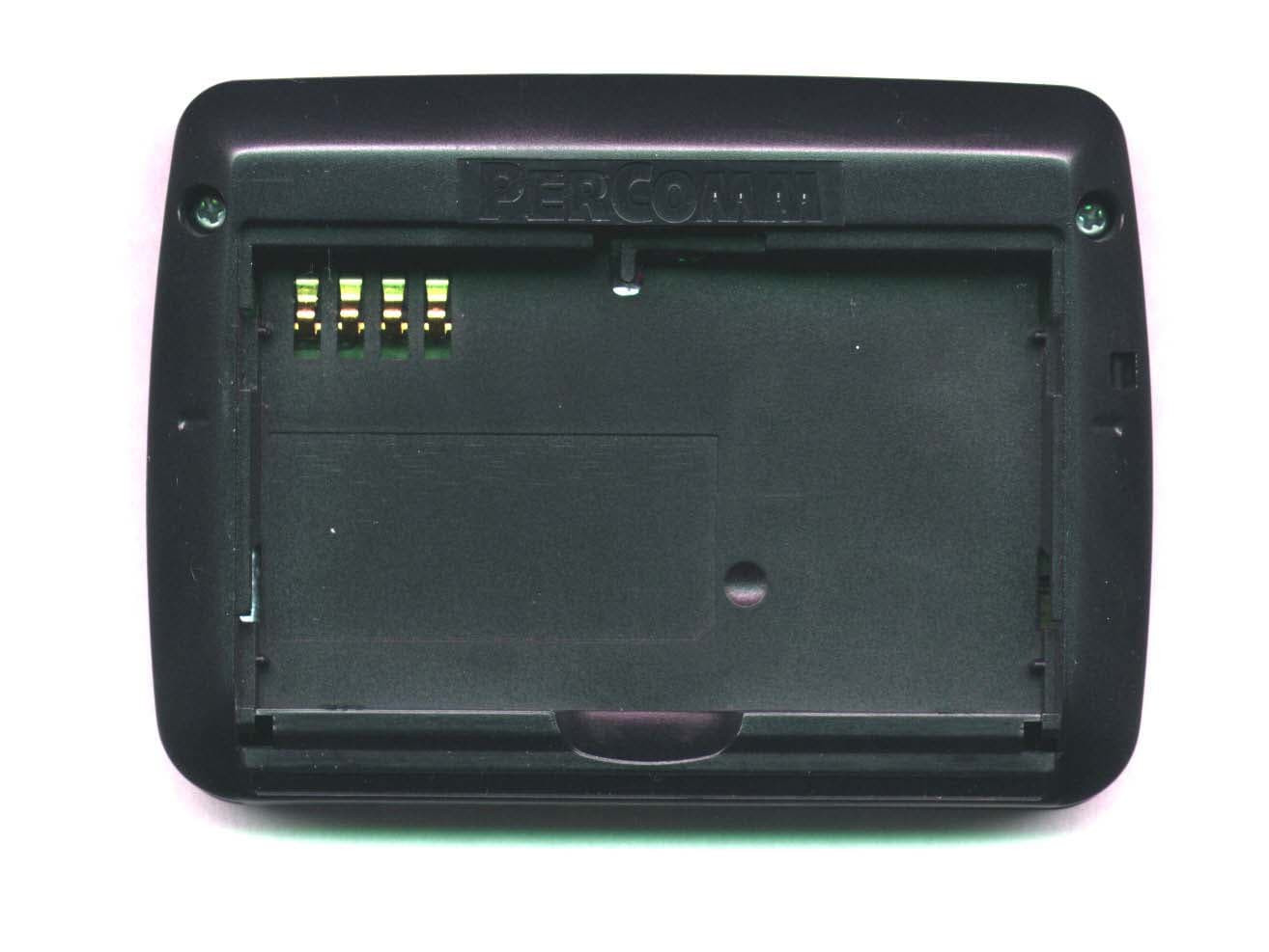
Click to zoom
Application Details
- Equipment Class
- PCT - PCS Licensed Transmitter worn on body
- Date of Grant
- Apr 16, 2003
- Application Purpose
- Original Equipment
- Date of Application
- Mar 09, 2003
- Equipment Note
- e80 2-way pager
- Frequency Range
- 901.00000000 - 902.00000000
- Company
- PerComm Inc
- Country
- United States
Documents & Files
Document Text
Text extracted from the exhibit documents filed with the FCC. Open a document above to read the original.
Users Manual
REVISION 2: 3/10/03 © 2003 PerComm, Inc. e80 Device Quick Start Guide LC D d i s p l a y : M a i n M en u ap pea r s h er e P e r C o m m E N T E R E S C M E N U D E L A L T C A P S S P A C E Q W E A S R T G F V B H Y U I K N L , M J O P . C Z X D Joystick Control keys Insert power cable here Control keys MAIN MENU SEND A MESSAGE FOLDERS INBOX ADDRESS BOOK NEWS PREFERENCES OUTBOX POWER OFF CONTROL KEYS ESC - Exit from current menu or text screen. - Press and hold to turn backlight on or off. MENU - Display a popup menu (if one is available). ENTER - Select highlighted item or next option in an option field or checkbox. CAPS/SHIFT - Once to enter an uppercase letter. - Twice for Shift Lock (all uppercase). - Once again to return to lowercase characters. ALT - Once to enter a number or special character. - Twice for ALT Lock (all numbers or special characters). - Once again to return to normal characters. ALT-ENTER - Return to Main Menu. ALT-DEL - Clear (delete) all characters to the left of the cursor (while editing text). For more information, see the e80 Personal Messaging Device Reference Guide on the accompanying CD-ROM. Getting Started © 2003 PerComm, Inc. REVISION 2: 3/10/03 INSTALL THE BATTERY Figure showing battery cover being removed Remove the battery cover by pressing down and outwards on the cover thumb grip. Figure showing battery being installed Position the PerComm Lithium Ion battery as shown, oriented so that the metal contacts on the back of the battery line up with the metal contacts inside the cabinet. Figure showing battery being installed Rotate the battery down into the cabinet while holding the lower edge in firmly, until it is in place with label facing up. Do not force the battery in; if properly lined up it should snap in easily. Figure showing battery cover being replaced Replace the battery cover: position the cover tabs in the slots on both cabinet sides and slide the cover forward until the tongue on the leading edge snaps into place. Use only a PerComm Lithium Ion battery in your e80 device. Any other battery type may cause damage. CHARGE THE BATTERY Figure showing power cord being inserted Insert the power cable as shown in the illustration. Plug the AC/DC transformer into an AC power source. Charging will begin immediately. Figure showing battery charging indicator When the battery is completely charged as indicated on the LCD display, unplug the power cable at both ends. Your e80 device is now ready for use. SET DATE / TIME AND OWNER INFORMATION Select PREFERENCES in the Main Menu. Select Owner Information and enter your name, phone number and any comments. When done, press ESC to save changes and exit. Select Date and Time. Push the joystick and to move from field to field and press to select entries in each field. When done, press ESC to save changes and exit. Using Your e80 Device REVISION 2: 3/10/03 © 2003 PerComm, Inc. SEND A MESSAGE Send A Message Select SEND A MESSAGE in the Main Menu. Press MENU and select Add Contact or Manual Entry to enter address. Type message in the Msg: field, press MENU and select Send. Resend A Message Select OUTBOX in the Main Menu. Highlight a message to resend, press MENU and select Resend. INBOX MESSAGES Select INBOX in the Main Menu. Read A Message Highlight a message and press the joystick to open the message for viewing. Forward A Message While reading a message, press MENU and select Forward. Enter address in To: field, press MENU and select Send. Delete A Message Highlight message to delete, press MENU and select Delete. Reply To A Message While reading a message, press MENU and select Reply. Press MENU again and select an automatic reply message. Or, select Compose Reply and enter a reply message, then press MENU and select Send. NEWS MESSAGES Select NEWS in the Main Menu. You can Read, Forward, and Delete news messages in the same way as for Inbox messages. THE ADDRESS BOOK Select ADDRESS BOOK in the Main Menu. Add A Contact Or Group Press MENU and select New Contact or New Group. Enter information as required. When done, press MENU and select Save. View A Contact Or Group Highlight a contact or group and press the joystick to view details. Using Your e80 Device © 2003 PerComm, Inc. REVISION 2: 3/10/03 Edit/Delete A Contact/Group Highlight a contact or group. Press MENU and select Edit or Delete (Contact/Group). After editing, press MENU and select Save. MEMOS AND PERSONAL FOLDERS Select FOLDERS in the Main Menu. View A Memo Highlight the desired memo in the Memos folder and press the joystick. Create A Memo In the Memos folder, press MENU and select New Memo. Enter memo label in Label: field and memo text in Text: field. When done press MENU and select Save. Edit/Delete A Memo Highlight a memo in the Memos folder to edit or delete. Press MENU and select Edit or Delete. After editing, press MENU and select Save. Add A Subfolder In News Archive/Personal Folders Select the News Archive or Personal folder. Press MENU and select New Folder. Enter a name for the subfolder, press MENU and select Save. SET PREFERENCES Select PREFERENCES in the Main Menu. Set the Mailbox Alert Select Mailbox Alerts and make changes to alert volume and type of alert for different kinds of messages. Press ESC to save and exit. Set an Alarm Select Alarm Clock and make changes to alert volume and alarm time and frequency for one or two different alarms. Press ESC to save and exit. Set Other Options Select another option to modify: Private Time, Quick Text, Signature, Address Book or Options (display features). Make changes, then press ESC to save and exit. ...AND MORE For more features and ways to use your e80 device, see the e80 Personal Messaging Device Reference Guide on the accompanying CD-ROM . RF EXPOSURE: the e80 device meets all FCC RF exposure guidelines when hand-held or used with PerComm supplied accessories.
Users Manual
REVISION 2: 3/10/03 e80 Personal Messaging Device Reference Guide e80 Personal Messaging Device Reference Guide 2 REVISION 2: 3/10/03 © 2003 PerComm, Inc. © Copyright 2003 PerComm, Inc. All rights reserved. e80 Personal Messaging Device Reference Guide © 2003 PerComm, Inc. REVISION 2: 3/10/03 3 Contents 1. Safety Information and FCC Compliance........................................... 4 1.1 RF Operational Characteristics .................... 4 1.2 Exposure to Radio Frequency Energy ......... 4 1.3 e80 Device Operation and EME Exposure .. 4 1.4 Safety and General Information ................... 5 1.5 Operational Warnings................................... 5 1.6 Operational Cautions.................................... 6 1.7 FCC Compliance .......................................... 6 2. Getting Started ..................................... 7 2.1 Unpacking Your e80 Device......................... 7 2.2 Installing the Battery..................................... 7 2.3 Charging the Battery .................................... 8 2.4 Attaching the Lanyard .................................. 8 3. About Your e80 Personal Messaging Device ................................................... 9 3.1 The External Connector ............................... 9 3.2 The Back Light ............................................. 9 3.3 The LCD Display ........................................ 10 3.4 The Joystick: Navigating in Different Modes11 3.5 The Keyboard ............................................. 12 3.6 Navigation Conventions in this Manual ...... 13 4. Setting Up Your e80 Device .............. 14 4.1 Viewing System Information....................... 14 4.2 Entering Owner Information ....................... 15 4.3 Setting Date and Time................................ 15 4.4 Turning Your e80 Device Off and On......... 16 5. Sending Messages............................. 17 5.1 Entering an Address Manually ................... 17 5.2 Selecting a Contact from the Address Book17 5.3 Editing or Adding a Manual Address Entry 18 5.4 Composing your Message.......................... 18 5.5 Sending your Message............................... 19 6. Managing Incoming Messages ......... 20 6.1 Reading a Message ................................... 20 6.2 Replying to a Message............................... 20 6.3 Forwarding a Message............................... 21 6.4 Deleting Messages..................................... 21 7. Managing Outgoing Messages ......... 22 7.1 Reviewing Sent Messages ......................... 22 7.2 Canceling a Sent Message ........................ 22 7.3 Resending a Message................................ 22 7.4 Deleting Messages..................................... 22 8. Other Messaging Options ................. 23 8.1 Creating Quick Text for Messages..............23 8.2 Customizing the New Message Alert ..........24 8.3 Setting a Message Timestamp ...................25 8.4 Creating an Automatic Signature ................25 8.5 Saving Messages in the Personal Folder ...26 9. Managing the Address Book ............ 27 9.1 Adding a Contact to the Address Book .......27 9.2 Adding a Group to the Address Book .........28 9.3 Viewing Contact or Group Information........29 9.4 Editing a Contact or Group .........................29 9.5 Deleting a Contact or Group .......................30 9.6 Forwarding a Contact..................................30 9.7 Customizing your Address Book.................30 10. Reading News .................................... 32 10.1 Reading a News Message ..........................32 10.2 Forwarding News ........................................32 10.3 Deleting News .............................................32 10.4 Reordering News Folders ...........................34 10.5 Customizing News Alerts ............................34 10.6 Saving News in the News Archive Folder ...35 11. Creating and Managing Memos ....... 36 11.1 Creating a Memo.........................................36 11.2 Viewing a Memo..........................................36 11.3 Editing a Memo ...........................................36 11.4 Deleting a Memo .........................................37 11.5 Inserting a Memo into a Message...............37 12. Managing Personal Folders.............. 38 12.1 Creating a New Subfolder for Mail or News Messages....................................................38 12.2 Editing a Subfolder Name ...........................39 12.3 Deleting Subfolders.....................................39 13. Setting Personal Options.................. 40 13.1 Setting Up the Alarm Clock.........................40 13.2 Alarm Alerts.................................................41 13.3 Setting Private Time....................................42 13.4 Customizing Display Features ....................42 14. Maintenance....................................... 44 14.1 General Care...............................................44 14.2 Battery Care ................................................44 14.3 Charging the Battery ...................................44 14.4 Removing and Replacing the Battery .........44 15. Troubleshooting ................................ 46 16. Index ................................................... 47 e80 Personal Messaging Device Reference Guide 4 REVISION 2: 3/10/03 © 2003 PerComm, Inc. 1. Safety Information and FCC Compliance IMPORTANT INFORMATION ON SAFE AND EFFICIENT OPERATION. READ THIS INFORMATION BEFORE USING YOUR e80 PERSONAL MESSAGING DEVICE. 1.1 RF Operational Characteristics Your e80 Personal Messaging Device contains a transmitter and a receiver. When it is ON, it receives and transmits radio frequency (RF) energy. The e80 device operates in the frequency range of 900 MHz to 1990 MHz and employs digital modulation techniques. When you communicate with your e80 device, the system handling your call controls the power level at which your e80 device transmits. The output power level typically may vary over a range from 0.063 watts to 1.5…
Text truncated - open the document above for the full version.
Cover Letter(s)
Corporate Office 22 Tower Office Park Woburn, MA 01801-2113 USA Telephone: +1 781-860-7700 Fax: +1 781-860-0618 February 28, 2003 Federal Communications Commission 7435 Oakland Mills Road Columbia, MD 21046 USA Confidentiality of Material Request This letter is to comply with Section 0.457(d)(2)(i) pertaining to confidential material. Percomm, Inc. would like the following documents regarding this submission for FCC ID: NNT1100 to be kept confidential. 1. Schematics – 9 files 2000-02639sd0xB1.pdf 2. Schematics – 1 file 2000-02642sd0xb.pdf 3. Theory of Operation (TEO) –1 file The above material contains trade secrets or technical data, which would customarily be guarded from competitors. We do not want these documents to be accessible to the general public. Sincerely, Dated this February 28, 2003 Radu Oprea By: ____________________________ ____________________ Signature Printed Senior RF Engineer Telephone: 604-293-5217 Applicant: PerComm, Inc.
External Photos
Corporate Office 22 Tower Office Park Woburn, MA 01801-2113 USA Telephone: +1 781-860-7700 Fax: +1 781-860-0618 EXTERNAL PHOTOS OF THE TWO-WAY PAGER, e80, MODEL 1100 FCC PART 2.1033(c)(12) DATE OF ISSUE: MARCH 5, 2003 Photos e80, MODEL 1100 Front view of the e80 device Back view of the e80 device Photos e80, MODEL 1100 Back view of the e80 device with the battery cover removed View of the serial interface and power connector of the e80 device
ID Label/Location Info
Corporate Office 22 Tower Office Park Woburn, MA 01801-2113 USA Telephone: +1 781-860-7700 Fax: +1 781-860-0618 LABEL DRAWING OF THE TWO_WAY PAGER, e80, MODEL 1100 FCC PART 2.1033(c)(11) DATE OF ISSUE: MARCH 5, 2003 Label ID e80, MODEL 1100 Label ID e80, MODEL 1100 Placement of the FCC ID label FCC ID Marking is printed on a label placed inside the battery compartment.
Internal Photos
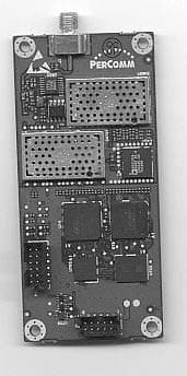
Corporate Office 22 Tower Office Park Woburn, MA 01801-2113 USA Telephone: +1 781-860-7700 Fax: +1 781-860-0618 INTERNAL PHOTOS OF THE TWO-WAY PAGER, e80, MODEL 1100 FCC PART 2.1033(c)(12) DATE OF ISSUE: MARCH 6, 2003 Internal Photos e80, Model 1100 Top view of the main board of the e80 device Bottom view of the main board of the e80 device Internal Photos e80, Model 1100 Top view of the display board of the e80 device Internal Photos e80, Model 1100 Bottom view of the display board of the e80 device Antenna view of the e80 device
Parts List/Tune Up Info
Corporate Office 22 Tower Office Park Woburn, MA 01801-2113 USA Telephone: +1 781-860-7700 Fax: +1 781-860-0618 PART LIST FOR TWO-WAY PAGER, e80, MODEL 1100 FCC PART 2.1033(c)(10) DATE OF ISSUE: MARCH 5, 2003 Part List E80, MODEL 1100 Part List of Active Devices and Resonators on the Main PCB Schematic Ref. Designator Device Type Circuit Application Source Q400, Q401 Dual PFET Switch FAIRCHILD SEMICONDUCTOR Q700 Dual NPN IF VCO NEC Q704, Q705, Q706, Q707, Q708, Q709 Dual NPN Buffer ON SEMICONDUCTOR U3 Bipolar IC Temp. Sensor NATIONAL SEMICONDUCTOR U14 CMOS IC Gate Array ATMEL U15 CMOS IC DSP TEXAS INSTRUMENTS INC. U100 Module VCTCXO RAKON LTD U101 BICMOS IC CODEC ANALOG DEVICES U400 BICMOS IC Voltage Regulator NATIONAL SEMICONDUCTOR U500 Bipolar IC Demodulator ANALOG DEVICES U501 Ga As IC RF Mixer INFINEON U502 Bipolar IC Low Noise Amplifier INFINEON U600 BICMOS IC Operational Amplifier NATIONAL SEMICONDUCTOR U602 Bipolar IC Buffer NEC U700 BICMOS IC PLL Synthesizer NATIONAL SEMICONDUCTOR U701 Module VCO DELTA U702 CMOS IC ROM SILCON STORAGE TECHNOLOGY U703 CMOS IC SRAM CYPRESS SEMICONDUCTOR U704 Bipolar IC Power on Reset ON SEMICONDUCTOR U707 Bipolar IC Modulator INFINEON U713 Ga-As IC Power Amplifier SKYWORKS U715 BICMOS IC Voltage Regulator ON SEMICONDUCTOR U716 MCU Micro-controller TEXAS INSTRUMENTS U717 CMOS IC Logic Gate FAIRCHILD SEMICONDUCTOR U718 Bipolar IC Battery Charger TEXAS INSTRUMENTS U719 CMOS IC Voltage Regulator TELCOM SEMICONDUCTOR Y1 Crystal 18.432 MHZ EPSON ELECTRONICS Y2 Crystal 32.768 KHZ FOX ELECTRONICS INC Y3 Ceramic 6 MHz Panasonic Part List of Active Devices and Resonators on the Display PCB U1 CMOS IC LCD controller Truly Semiconductors LTD U2 CMOS IC EL driver Panasonic
RF Exposure Info
Test Report S/N: 021903-340NNT Test Date(s): March 05, 2003 FCC SAR Evaluation © 2003 Celltech Labs Inc.1 of 20 Celltech Labs Inc. declares under its sole responsibility that this device was found to be in compliance with the Specific Absorption Rate (SAR) RF exposure requirements specified in FCC 47 CFR §2.1093 and Health Canada’s Safety Code 6. The device was tested in accordance with the measurement standards and procedures specified in FCC OET Bulletin 65, Supplement C, Edition 01-01 for the General Population / Uncontrolled Exposure environment. I attest to the accuracy of data. All measurements were performed by me or were made under my supervision and are correct to the best of my knowledge and belief. I assume full responsibility for the completeness of these measurements and vouch for the qualifications of all persons taking them. This test report shall not be reproduced partially, or in full, without the prior written approval of Celltech Labs Inc. The results and statements contained in this report pertain only to the device(s) evaluated. Russell Pipe Senior Compliance Technologist Celltech Labs Inc. DECLARATION OF COMPLIANCE SAR EVALUATION Test Lab CELLTECH LABS INC. Testing and Engineering Lab 1955 Moss Court Kelowna, B.C. Canada V1Y 9L3 Phone: 250-448-7047 Fax: 250-448-7046 e-mail: [email protected] web site: www.celltechlabs.com Applicant Information PERCOMM TECHNOLOGIES INC. 3999 Henning Drive, Unit 402 Burnaby, BC V5C 6P9 Canada Rule Part(s):FCC 47 CFR §2.1093, §24(D) Test Procedure(s):FCC OET Bulletin 65, Supplement C (01-01) Device Classification:Part 24 Licensed Portable Transmitter worn on body (PCT) Device Type:ReFLEX Two-Way Pager FCC ID:NNT1100 Model Name:e80 Model No.:1100 Tx Frequency Range:901 - 902 MHz RF Output Power Tested:0.275 Watts ERP (24.4 dBm) Nominal Conducted Power:1 Watt Modulation:CPFSK Antenna Type(s):Internal Battery Type(s):3.6V Lithium-ion Max. SAR Measured:Body: 1.07 W/kg (1g average) Hand: 1.49 W/kg (10g average) Test Report S/N: 021903-340NNT Test Date(s): March 05, 2003 FCC SAR Evaluation © 2003 Celltech Labs Inc.2 of 20 TABLE OF CONTENTS 1.0INTRODUCTION..................................................................... 3 2.0DESCRIPTION OF EUT............................................................ 3 3.0SAR MEASUREMENT SYSTEM ............................................... 4 4.0MEASUREMENT SUMMARY..................................................... 5 5.0DETAILS OF SAR EVALUATION............................................... 6 6.0EVALUATION PROCEDURES................................................... 6 7.0SYSTEM PERFORMANCE CHECK............................................ 7 8.0EQUIVALENT TISSUES........................................................... 8 9.0SAR LIMITS........................................................................... 8 10.0SYSTEM SPECIFICATIONS...................................................... 9 11.0PROBE SPECIFICATION......................................................... 10 12.0SAM PHANTOM...................................................................... 10 13.0DEVICEHOLDER.................................................................... 10 14.0TEST EQUIPMENT LIST........................................................... 11 15.0MEASUREMENT UNCERTAINTIES............................................ 12 16.0REFERENCES.......................................................................13 APPENDIX A - SAR MEASUREMENT DATA............................................14 APPENDIX B - SYSTEM CHECK DATA.................................................... 15 APPENDIX C - SYSTEM VALIDATION..................................................... 16 APPENDIX D - PROBE CALIBRATION.................................................... 17 APPENDIX E - MEASURED FLUID DIELECTRIC PARAMETERS................ 18 APPENDIX F - SAM PHANTOM CERTIFICATE OF CONFORMITY.............. 19 APPENDIX G - SAR TEST SETUP & EUT PHOTOGRAPHS........................ 20 Test Report S/N: 021903-340NNT Test Date(s): March 05, 2003 FCC SAR Evaluation © 2003 Celltech Labs Inc.Percomm Technologies Inc. FCC ID: NNT11003 of 20 ReFLEX Two-Way Pager Model: e80 1100 (901-902MHz) 1.0 INTRODUCTION This measurement report demonstrates that the Percomm Technologies Inc. ReFLEX Two-Way Pager FCC ID: NNT1100 complies withthe RF exposure requirements specified in FCC 47 CFR §2.1093 (see reference [1]) for the General Population / Uncontrolled Exposure environment. The test procedures described in FCC OET Bulletin 65, Supplement C, Edition 01-01 (see reference [2]) were employed. A description of the product, operating configuration, detailed summary of the test results, methodology and procedures used in the evaluation, equipment used, and the various provisions of the rules are included within this test report. 2.0 DESCRIPTION of Equipment Under Test (EUT) FCC Rule Part(s)47 CFR §2.1093; §24(D) FCC Test Procedure(s)OET Bulletin 65, Supplement C (01-01) FCC Device ClassificationLicensed Portable Transmitter worn on body (PCT) Device TypeReFLEX Two-Way Pager FCC IDNNT1100 Model NameE80 Model No.1100 Serial No.Pre-production ModulationCPFSK Tx Frequency Range901 - 902 MHz RF Output Power Tested0.275 Watts ERP (24.4 dBm) Nominal Conducted Power1 Watt Antenna Type(s)Internal Battery Type(s)3.6V Lithium-ion Test Report S/N: 021903-340NNT Test Date(s): March 05, 2003 FCC SAR Evaluation © 2003 Celltech Labs Inc.Percomm Technologies Inc. FCC ID: NNT11004 of 20 ReFLEX Two-Way Pager Model: e80 1100 (901-902MHz) 3.0 SAR MEASUREMENT SYSTEM Celltech Research SAR measurement facility utilizes the Dosimetric Assessment System (DASY™) manufactured by Schmid & Partner Engineering AG (SPEAG™) of Zurich, Switzerland. The DASY system is comprised of the robot controller, computer, near-field probe, probe alignment sensor, specific anthropomorphic mannequin (SAM) phantom, and various planar phantoms for face-held and/or body-worn SAR evaluations. The robot is a six-axis…
Text truncated - open the document above for the full version.
Test Report
Corporate Office 22 Tower Office Park Woburn, MA 01801-2113 USA Telephone: +1 781-860-7700 Fax: +1 781-860-0618 TECHNICAL REPORT FOR THE TWO WAY PAGER, e80, MODEL 1100 FCC PART 24 SUBPART D AND FCC PART 15 SUBPART B SECTION 15.107 AND 15.109 CLASS B COMPLIANCE DATE OF ISSUE: FEBRUARY 28, 2003 PREPARED BY: Radu Oprea PerComm, Inc. 3999 Henning Drive, Unit 402 Burnaby, BC, V5C 6P9 Canada Date of test: Feb 23 to March 7, 2003 This report contains a total of 6 pages. Page 1 of 6 Technical Report e80, MODEL 1100 DESCRIPTION OF THE EQUIPMENT UNDER TEST PerComm e80 two-way pager is a handheld unit designed for two-way wireless communication over a ReFLEX network. A Lithium Ion rechargeable battery powers the device. The device antenna is integral to the unit. Technical characteristics 1. Output Power 1 Watt (conducted) 2. Frequency Range • Transmitter 896-902 MHz • Receiver 929-941 MHz 3. Channel Spacing • Transmitter 12.5 kHz in 6.25Khz steps • Receiver 6.25, 10 and 12.5 kHz 4. Data rates • Transmitter 800, 1600, 6400 and 9600 bits per second • Receiver 1600, 3200 and 6400 bits per second 5. Modulation • Transmitter 4-level continuous phase frequency shift keying • Receiver 2-level and 4-level CPFSK 6. Frequency deviation +/- 800 and +/-2400 Hz 7. Frequency stability 1 ppm EQUIPMENT UNDER TEST ReFLEX Telemetry Device Manufacturer: PerComm, Inc Model Name: e80 Model Number: 1100 FCC ID NNT1100 (pending) PERIPHERAL DEVICES The EUT was tested in three configurations: the unit by itself, the unit with an AC/DC power adaptor charging the battery and the unit with a serial cable attached to its serial connector. 2.1033(c)(3) USER’S MANUAL There are two user manuals. One is the e80 Quick Guide and the other is the e80 Reference Manual. Page 2 of 6 Technical Report e80, MODEL 1100 2.1033(c)(4) TYPE OF EMISSIONS The emission designator is 10K0F1D. Bandwidth calculation Type of modulation: CPFSK continuous phase 4-level frequency shift keying. Deviation: D= 2400 Hz maximum. Maximum symbol rate = 9600 bits per second/2 bits per symbol = 4800 symbol per second. Maximum modulation frequency: M = 4800 symbols/2symbols per cycle = 2400 Hz. Necessary bandwidth: B n is given by: B n = 2*M + 2*D = 2*2400 + 2*2400=9600 Hz Hence the bandwidth designator is 10K0. The last three symbols are F for frequency modulation, 1 for a single channel containing digital information without the use of a modulating sub-carrier and D for data transmission. 2.1033(c)(5) FREQUENCY RANGE The device operates in the frequency range of 901-902 MHz. 2.1033(c)(6) OPERATING POWER The Pout is 1watt. The output power is measured in conducted conditions in the lab or in manufacturing conditions prior to the unit assembly and prior to mounting the antenna. 2.1033(c)(7) MAXIMUM POWER RATING Per FCC Part 24.132(a) stations transmitting in the 901-902 MHz band are limited to 7 watts E.R.P. 2.1033(c)(8) DC VOLTAGES The e80 two-way pager operates from a Lithium Ion battery. The battery voltage in normal mode of operation ranges from 4.2V to 3.4V. The PA is powered straight from the battery. The DC current consumption in the PA’s stage is typical 600 mA. Page 3 of 6 Technical Report e80, MODEL 1100 2.1033(c)(9) TUNE-UP PROCEDURE There is no tune-up procedure for the output power as it is fixed to the maximum output power supplied by the final RF power amplifier stage. The voltage on the power amplifier can be lowered and as a consequence the output power diminishes. 2.1033(c)(10) SCHEMATICS AND CIRCUITRY DESCRIPTION The necessary information is contained in separate confidential documents. 2.1033(c)(11) LABEL AND PLACEMENT The necessary information is contained in the document FCC Label. 2.1033(c)(12) SUBMITTAL PHOTOS The necessary information is contained in two files one containing the External Photos and one with the Internal Photos. 2.1033(c)(13) MODULATION INFORMATION The necessary information is contained in the PerComm Report. 2.1033(c)(14)/2.1046/24.132(a) RF POWER OUTPUT The necessary information is contained in the Protocol Labs Report. 2.1033(c)(14)/2.1047(d)/24.131 MODULATION CHARACTERISTIC Part 2.1047(a) is Not Applicable to the e80 device. Part 2.1047(b) is Not Applicable to the device. The e80 does not employ modulation limiting. The samples of the complex envelope of the signal are generated by the DSP via software. Two D-to-As convert these samples in analog I/Q signals. These analog signals modulates an IF carrier that later on is up- converted to the transmit frequency. The over-modulation is prevented because the DSP is controlling the frequency deviation. The TIA/EIA-603-A method of measuring the modulation limiting is Not Applicable. Part 2.1047(d) the necessary information is contained in the PerComm Report. Page 4 of 6 Technical Report e80, MODEL 1100 2.1033(c)(14)/2.1049(i)/24.131 OCCUPIED BANDWIDTH The necessary information is contained in the PerComm Report. 2.1033(c)(14)/2.1051 SPURIOUS EMISSIONS AT THE ANTENNA TERMINAL The internal antenna does not allow this type of measurement. 2.1033(c)(14)/2.1053/24.133 FIELD STRENGTH OF SPURIOUS RADIATION The necessary information is contained in the Protocol Labs Report. 2.1033(c)(14)/2.1055/24.135 FREQUENCY STABILITY The necessary information is contained in the PerComm Report. 2.1093 RADIOFREQUENCY RADIATION EXPOSURE EVALUATION The necessary information is contained in the document SAR Report. The SAR measurements were performed with a duty cycle of 25%, higher than the maximum duty cycle allowed in the ReFLEX protocol. A calculation of the worst duty cycle is presented below. The worst-case duty cycle for the e80 device transmitter occurs on a collapse rate of 1 when the device is sending messages to the infrastructure. For this calculation, we assume infinite messages are queued in the device; each message is the maximum length allowed (700 bytes) and the back channel is running at its slowest speed (800 bps). The ReFLEX protocol is timed on frames, each being 1.875 seconds l…
Text truncated - open the document above for the full version.
Test Report
Corporate Office 22 Tower Office Park Woburn, MA 01801-2113 USA Telephone: +1 781-860-7700 Fax: +1 781-860-0618 MEASUREMENT REPORT FOR THE TWO WAY PAGER, e80, MODEL 1100 FCC PART 2.1033(c)(13) FCC PART 2.1033(c)(14) (PARTIAL) COMPLIANCE DATE OF ISSUE: FEBRUARY 28, 2003 PREPARED BY: Radu Oprea PerComm, Inc. 3999 Henning Drive, Unit 402 Burnaby, BC, V5C 6P9 Canada This report contains a total of 8 pages. Page 1 of 8 Measurement Report Rev. 1.0 e80, MODEL 1100 INDEX MODULATION INFORMATION..............................................................3 MODULATION CHARACTERISTIC.........................................................5 OCCUPIED BANDWIDTH......................................................................6 FREQUENCY STABILITY VERSUS TEMPERATURE....................................7 FREQUENCY STABILITY VERSUS SUPPLY VOLTAGE..............................8 Page 2 of 8 Measurement Report Rev. 1.0 e80, MODEL 1100 Modulation Information: FCC Part 2.1033(c)(13) Base-band Splatter Filter Response The base band filtering of the data is done digitally in the DSP. Therefore there is no measured filter response, but the filter characteristic can be calculated. The base-band filter frequency response has been plotted in MATLAB. The filter is a Gaussian filter with BT=0.4896, it has linear phase and only the amplitude characteristic is shown. Filtered Base-band Data and Demodulated Data The e80 device was placed inside the TEM cell and the TEM cell’s port was connected to the vector signal analyzer (VSA). The VSA was configured as an analog frequency demodulator. The e80 transmitted a carrier modulated with a random pattern of data. The demodulated data was captured and is presented in the plot bellow. It was possible to reconstruct the discrete 4 level data from the waveform and that data was used to generate an ideal filtered base-band data. The plot of the calculated base-band data is shown on a separate plot. List of Test Equipment 1. Vector Signal Analyzer, Hewlett Packard, Model No. 89441A, S/N 3416A00986. 2. TEM cell, TESCOM, Model TC-5060…
Text truncated - open the document above for the full version.
Contact Information
Applicant
Larisa Yee
781 860-7700Fax: 781 860-0618
Technical Contact
PerComm TechnologiesRadu Oprea
[email protected]604-293-5217
3999 Henning Drive, Unit 402 · Burnaby · Canada
Non-Technical Contact
PerComm Inc.Larisa Yee
[email protected]781-860-7700
Test Firm
Protocol LabsRobert Stirling
Technical Specifications
| # | Rule Parts | Frequency Range | Power Output | Emission | Tolerance |
|---|---|---|---|---|---|
| 1 | 24D | 901 MHz - 902 MHz | 363.00 mW | 10K0F1D | 0.5000000000 ppm |
Other Applications from PerComm Inc
NNT1005
Dec 05, 2002Reflex Telemetry Device, OMNIDATA
Equipment Class
PCB - PCS Licensed TransmitterNNT-SL6000NP
Dec 18, 1997CXX - Communications Rcvr for use w/ licensed Tx and CBs
Equipment Class
CXX - Communications Rcvr for use w/ licensed Tx and CBsNNT-PN9000NP
Nov 04, 1997CXX - Communications Rcvr for use w/ licensed Tx and CBs
Equipment Class
CXX - Communications Rcvr for use w/ licensed Tx and CBs