FCCID.CO- FCC ID Database
HomeCompaniesEquipment ClassesSearch

Β© 2026 FCC ID Database. All rights reserved.

AboutContactData sourced from FCC public records
  1. Home/
  2. GE Harris Railway Electronics, L.L.C./
  3. NOLCCU1003067

NOLCCU1003067

GE Harris Railway Electronics, L.L.C.
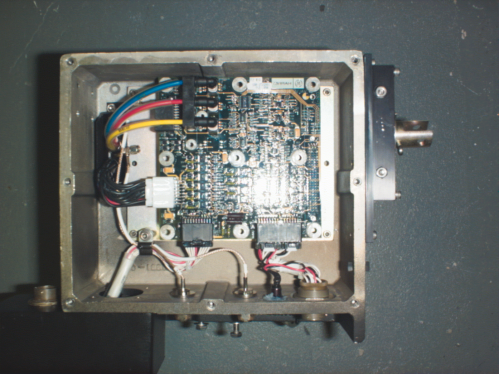
DSS - Part 15 Spread Spectrum Transmitter - FCC ID NOLCCU1003067 - GE Harris Railway Electronics, L.L.C.
Click to zoom

Application Details

Equipment Class
DSS - Part 15 Spread Spectrum Transmitter
Date of Grant
May 23, 1999
Application Purpose
Original Equipment
Date of Application
Apr 18, 1999
Frequency Range
2412.00000000 - 2467.00000000
Company
GE Harris Railway Electronics, L.L.C.
Country
United States

Documents & Files

Select a file to view

Users Manual

β†—

Attestation Statements

Cover Letter(s)

ID Label/Location Info

Internal Photos

β†—

Operational Description

β†—
β†—

Schematics

Document Text

Text extracted from the exhibit documents filed with the FCC. Open a document above to read the original.

Users Manual

GE Harris Railway Electronics, L.L.C. Proprietary and Confidential 4/16/99 1 Exhibit I CCU Installation Manual NOTE: Based on discussions with FCC personnel, GE Harris is submitting only the sections pertaining to the CCU and antenna unit. GE Harris Railway Electronics, L.L.C. Proprietary and Confidential 4/16/99 2 BHPIO EP Xβ„’ Direct Braking System Ore Car Installation Instructions April 1999 TM" EP x" and β€œTrainTalk” are trademarks of GE Harris Railway Electronics, L.L.C. LOCOTROL is a registered trademark of GE Harris Railway Electronics, L.L.C. GE Harris Railway Electronics, L.L.C. Proprietary and Confidential 4/16/99 3 Section 1 INTRODUCTION 1.1 SCOPE This document identifies the installation procedures used to install the GE Harris Train Talk Electronically Controlled Pneumatic Brake (ECPB) Valve and associated equipment and hardware onto a customer owned freight car, specifically a BHP Ore car manufactured by Goninan, (drawing number 076-M-153). 1.2 APPLICABLE DOCUMENTS The following documents are applicable. 1. 1002575-001 Ore Car Drawing 2. 1002407 GE Harris ECPB Freight Car Wiring Diagram - BHP 3. 1002180 GE Harris ECPB Freight Car Control Device (CCD) Assembly Drawing - BHP 4. 1002182-901 GE Harris Freight Car Modification Kit - BHP 5. 1002183-901 GE Harris Car Control Unit (CCU) Installation Hardware Kit - BHP 6. 1002188-901 GE Harris Generator Installation /Assembly /Hardware Kit - BHP 7. 1002577-901 GE Harris Antenna Installation /Assembly /Hardware Kit - BHP 8. 1002328-901 GE Harris Battery Box Installation / Assembly / Hardware Kit - BHP 9. TP1002546 Test Procedure, BHP 1.3 REQUIRED TOOLS & MATERIALS These items are required for proper installation: 1. Arc Welding Equipment 2.½” SQ DR ratchet handle with 3”-6” extension 3. ½” SQ DR torque wrench - 100-150 ft.-lbs. capacity 4. 3/8” SQ DR torque wrench - 80-100 in-lbs. capacity 5. 3/8” SQ DR 3”-6” extension 6. 15/16” socket for ½” SQ DR 7. 1/2” socket for ½” SQ DR 8. 9/16” socket for ½” SQ DR 9. 7/16” socket for 3/8” SQ DR GE Harris Railway Electronics, L.L.C. Proprietary and Confidential 4/16/99 4 10.7/16” combination box / open end wrench 11.1/2” combination box / open end wrench 12.9/16” combination box / open end wrench 13.13/16” combination box / open end wrench 14.5/32” Hex Driver (Allen Wrench) 15.Vise-Grip pliers 16.Pipe wrench 12” - 16” 17.Slip Joint Pliers 18.#2 Phillips screwdriver 19.#3 Phillips screwdriver 20.Generator coupler installation tool - 1000850-001 21.Liquid Wrench 22.Loctite Primer, Type N 23.Loctite Thread Sealer, #242 Blue 1.4 INSTALLATION INSTRUCTIONS The following instructions are divided into 5 sections: Section 2. Freight Car Modifications, Section 3. Generator and Cable Installation Section 4. CCU Installation Section 5. Antenna and Antenna Cable Installation Section 6. Battery Box and Power Cable Installation Section 7. Programming and Testing These instructions are arranged in the sequence that appears most convenient for the installers. If there are any questions, please contact: GE HARRIS RAILWAY ELECTRONICS, L.L.C. 407 JOHN RODES BLVD. MELBOURNE, FL, USA 32934 ATTN: DAVID KIRCHNER 407-752-3479 24. GE Harris Railway Electronics, L.L.C. Proprietary and Confidential 4/16/99 5 Section 2 CAR CONTROL UNIT (CCU) -1002173-901, 1002183-901 The CCU is supplied as one assembly - part number 1002173-901, which is mounted to the Pipe Bracket in place of the existing Service Valve, and to which one power cable and two antenna cables are attached. Installation hardware for the CCU is in kit 1002183-901. FIGURE 2 - 1 CAR CONTROL UNIT CAUTION: THIS EQUIPMENT HAS BEEN TESTED AND FOUND TO COMPLY WITH THE LIMITS FOR A CLASS A DIGITAL DEVICE, PURSUANT TO PART 15 OF THE FCC RULES. THESE LIMITS ARE DESIGNED TO PROVIDE REASONABLE PROTECTION AGAINST HARMFUL INTERFERENCE WHEN THE EQUIPMENT IS OPERATED IN A COMMERCIAL ENVIRONMENT. THIS EQUIPMENT GENERATES, USES, AND CAN RADIATE RADIO FREQUENCY ENERGY AND, IF NOT INSTALLED AND USED IN ACCORDANCE WITH THE INSTRUCTION MANUAL, MAY CAUSE HARMFUL INTERFERENCE TORADIO COMMUNICATIONS. OPERATION OF THIS EQUIPMENT IN A RESIDENTIAL AREA IS LIKELY TO CAUSE HARMFUL INTERFERENCE IN WHICH CASE THE USER WILL BE REQUIRED TO CORRECT THE INTERFERENCE AT HIS OWN EXPENSE. GE Harris Railway Electronics, L.L.C. Proprietary and Confidential 4/16/99 6 CAUTION: USE OF ANY COMPONENTS OTHER THAN THOSE SUPPLIED OR AUTHORIZED BY GE HARRIS (I.E. TESTED TO MEET FCC REGULATIONS WITH THE TRAINTALK SYSTEM) IS A VIOLATION OF FCC REGUALTIONS. CHANGES OR MODIFICATIONS NOT EXPRESSEDLY APPROVED BY THE PARTY RESPONSIBLE FOR COMPLIANCE COULD VOID THE USER’S AUTHORITY TO OPERATE THE EQUIPMENT . CAUTION: AIR PRESSURE IN BRAKE CYLINDER AND ALL SERVICE AND EMERGENCY RESERVOIRS MUST BE RELEASED BEFORE WORK ON PIPE BRACKET MAY PROCEED. 1. Release or vent all air from Brake Cylinder and ALL Emergency and Service reservoirs on freight car. 2. Locate Pipe Bracket and brake valve assembly. Remove the cotter pin holding the Manual Release Push-Pull Rod to the Service valve. Remove three 5/8-11 nuts (15/16” hex) holding the service valve, and remove service valve and gasket. 3. Remove upper short 5/8” stud from pipe bracket. N OTE: CUSTOMER MAY REQUIRE THAT THE AIR FILTER BE REPLACED WHEN THE STRAINER NUT IS REPLACED. IF SO, CUSTOMER WILL SUPPLY NEW AIR FILTERS. 4. Remove Strainer Nut from pipe bracket and replace with new Modified Strainer Nut 1002418-001with larger hole from CCU Installation Kit 1002183-901; replace air filter if required by customer. 5. Examine lower two 5/8”studs: Outer threads should be clean and show no signs of cross threading. Length extension from pipe bracket should be 6-1/2” minimum with a minimum of 1.0” thread engagement in the pipe bracket. Replace if necessary with 5/8-11 x 8.0” studs in Hardware Kit 1002183-901. 6. Insure gasket surface of Pipe Bracket is clean and free of loose dirt and debris. Place Service Valve Gasket from CCU Installation Kit 1002183-901 over the two lower studs, o…

Text truncated - open the document above for the full version.

Internal Photos

Document No. 5001365 16 April 1999 GE Harris Railway Electronics, L.L.C. Exhibit H Photographs Document No. 5001365 16 April 1999 GE Harris Railway Electronics, L.L.C. H.1 Photographs See also, Exhibit G: Intentional Radiator Test Report, Section 5.0: Test Sample Setup and Configurations. Document No. 5001365 16 April 1999 GE Harris Railway Electronics, L.L.C. Photo H.1 Internal View of the CCU Document No. 5001365 16 April 1999 GE Harris Railway Electronics, L.L.C. Photo H.2 CCU RF Chamber Test Setup at Rubicom Systems, Inc. Document No. 5001365 16 April 1999 GE Harris Railway Electronics, L.L.C. Photo H.3 CCU test setup at Rubicom Systems, Inc. Document No. 5001365 16 April 1999 GE Harris Railway Electronics, L.L.C. Photo H.4 Side view of CCU test setup at Rubicom Systems, Inc. Document No. 5001365 16 April 1999 GE Harris Railway Electronics, L.L.C. Photo H.5 Valve Interface Module board (top view) Document No. 5001365 16 April 1999 GE Harris Railway Electronics, L.L.C. Photo H.6 Valve Interface Module board (bottom view) Document No. 5001365 16 April 1999 GE Harris Railway Electronics, L.L.C. Photo H.7 ITCU Radio Board (top view) Document No. 5001365 16 April 1999 GE Harris Railway Electronics, L.L.C. Photo H.8 ITCU Radio Board (bottom view)

Operational Description

[2] [3] [4] [5] [6] [7] [8] [9] [10] [11] [12] [13] [14] [15] [16]

Operational Description

[2] [3] [4] [5] [6] [7] [8] [9] [10] [11] [12] [13] [14] [15] [16] [17] [18] [19] [20] [21] [22] [23] [24] [25] [26] [27] [28] [29] [30] [31] [32] [33] [34] [35] [36] [37] [38] [39] [40] [41] [42] [43] [44] [45] [46] [47] [48] [49] [50]

Contact Information

Applicant

Don Darby
[email protected]407-242-4404Fax: 407-242-5019

Technical Contact

GE HARRIS RAILWAY ELECTRONICS, L.L.C.DON DARBY
[email protected]407-242-4404

407 NORTH JOHN RODES BLVD. Β· MELBOURNE, Florida Β· United States

Non-Technical Contact

KOTEEN & NAFTALIN, L.L.P.GEORGE Y WHEELER
[email protected]202-467-5700

Test Firm

Advanced Compliance Solutions, Inc.Sam Wismer
[email protected]321-951-1710Fax: 321-951-2362

Technical Specifications

#Rule PartsFrequency RangePower Output
115C2.41 GHz - 2.47 GHz50.00 mW

Other Applications from GE Harris Railway Electronics, L.L.C.
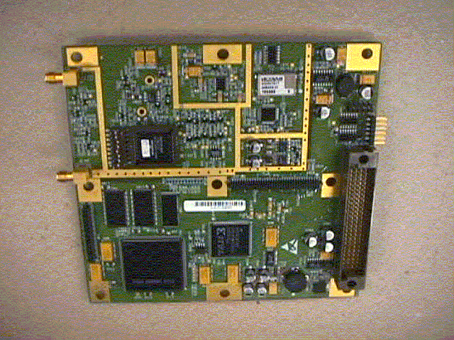
DSS - Part 15 Spread Spectrum Transmitter - FCC ID NOLLCM1003068 - GE Harris Railway Electronics, L.L.C.
NOLLCM1003068

DSS - Part 15 Spread Spectrum Transmitter

May 23, 1999

Equipment Class

DSS - Part 15 Spread Spectrum Transmitter