FCCID.CO- FCC ID Database
HomeCompaniesEquipment ClassesSearch

Β© 2026 FCC ID Database. All rights reserved.

AboutContactData sourced from FCC public records
  1. Home/
  2. GE Harris Railway Electronics, L.L.C./
  3. NOLLCM1003068

NOLLCM1003068

GE Harris Railway Electronics, L.L.C.
DSS - Part 15 Spread Spectrum Transmitter - FCC ID NOLLCM1003068 - GE Harris Railway Electronics, L.L.C.
Click to zoom

Application Details

Equipment Class
DSS - Part 15 Spread Spectrum Transmitter
Date of Grant
May 23, 1999
Application Purpose
Original Equipment
Date of Application
Apr 18, 1999
Frequency Range
2412.00000000 - 2467.00000000
Company
GE Harris Railway Electronics, L.L.C.
Country
United States

Documents & Files

Select a file to view
Users Manual

β†—
β†—

Attestation Statements

β†—
β†—
β†—

Cover Letter(s)

β†—

ID Label/Location Info

β†—
β†—

Internal Photos

β†—

Operational Description

β†—
β†—

Schematics

β†—
β†—

Test Report

β†—
β†—
β†—

Document Text

Text extracted from the exhibit documents filed with the FCC. Open a document above to read the original.

Users Manual

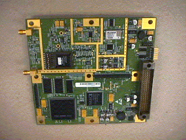
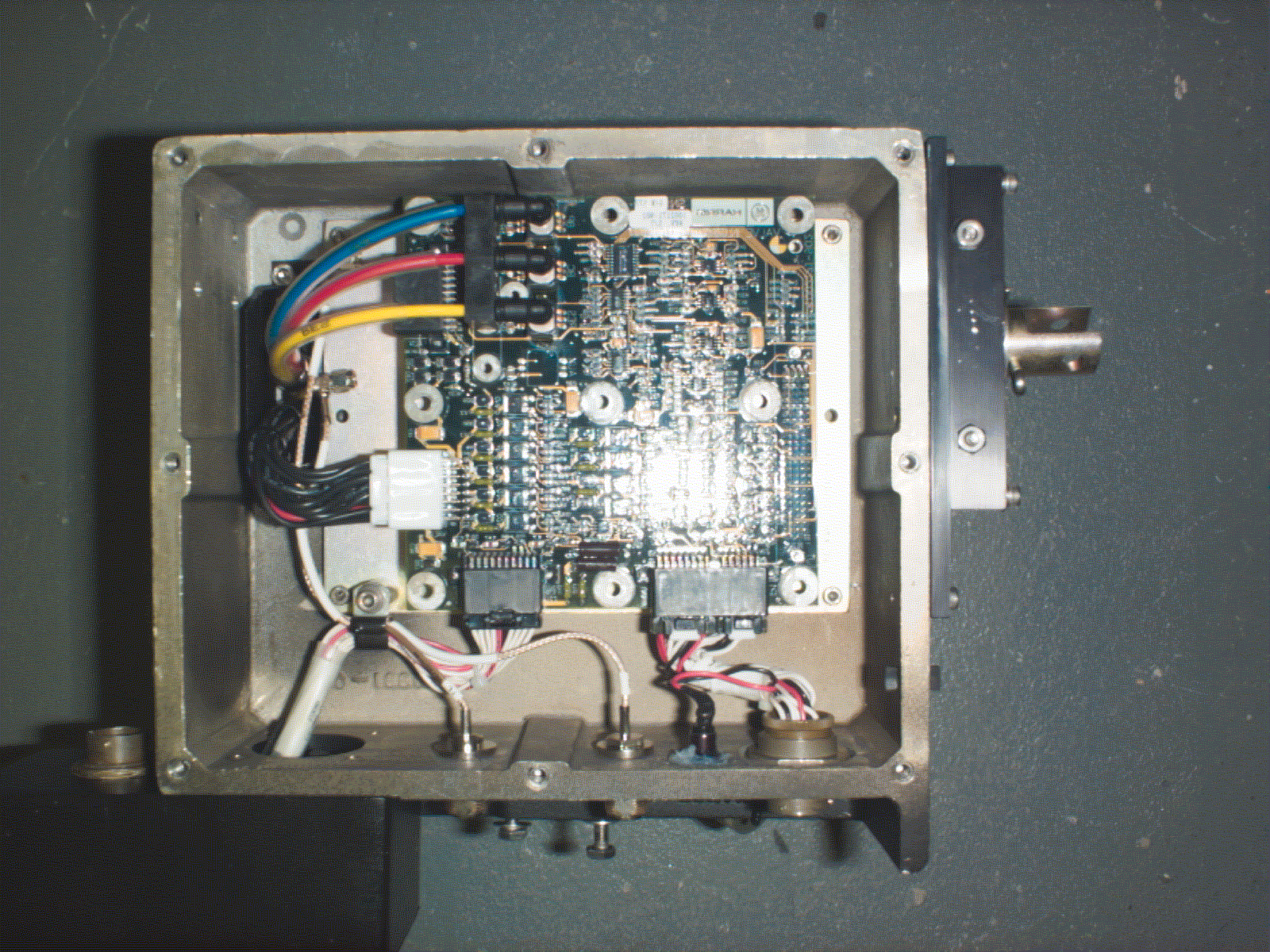
Document No. 5001366 16 April 1999 GE Harris Railway Electronics, L.L.C. Exhibit H Photographs Document No. 5001366 16 April 1999 GE Harris Railway Electronics, L.L.C. H.1 Photographs See also, Exhibit G: Intentional Radiator Test Report, Section 5.0: Test Sample Setup and Configurations. Document No. 5001366 16 April 1999 GE Harris Railway Electronics, L.L.C. Photo H.1 Internal view of LCM Document No. 5001366 16 April 1999 GE Harris Railway Electronics, L.L.C. Photo H.2 LCM RF chamber test setup at Rubicom Systems, Inc. Document No. 5001366 16 April 1999 GE Harris Railway Electronics, L.L.C. Photo H.3 LCM test setup at Rubicom Systems, Inc. Document No. 5001366 16 April 1999 GE Harris Railway Electronics, L.L.C. Photo H.4 Side view of the LCM Document No. 5001366 16 April 1999 GE Harris Railway Electronics, L.L.C. Photo H.5 Valve Interface Module board (top view) Document No. 5001366 16 April 1999 GE Harris Railway Electronics, L.L.C. Photo H.6 Valve Interface Module board (bottom view) Document No. 5001366 16 April 1999 GE Harris Railway Electronics, L.L.C. Photo H.7 ITCU Radio Board (top view) Document No. 5001366 16 April 1999 GE Harris Railway Electronics, L.L.C. Photo H.8 ITCU Radio Board (bottom view) Document No. 5001366 16 April 1999 GE Harris Railway Electronics, L.L.C. Photo H.9 PCR Interface Card (top view) Photo H.10 PCR Interface Card (bottom view) Document No. 5001366 16 April 1999 GE Harris Railway Electronics, L.L.C. Photo H.11 Personality Module board (top view) Photo H.12 Personality Module board (bottom view) Document No. 5001366 16 April 1999 GE Harris Railway Electronics, L.L.C. Photo H.13 Wilmore DC-DC Converter

Attestation Statements

Document No. 5001365 15 March 1999 GE Harris Railway Electronics, L.L.C.1 EPx/TrainTalk Car Control Unit FCC Certification Package Document No. 5001365 15 March 1999 GE Harris Railway Electronics, L.L.C.2 EPx/TrainTalk Car Control Unit FCC Certification Package Prepared by: Date: Approved by: Date: Approved by: Date: Document No. 5001366 16 April 1999 GE Harris Railway Electronics, L.L.C.1 TABLE OF CONTENTSLocomotive Communication Module FCC Certification Plan Package Document No. 5001366 16 April 1999 GE Harris Railway Electronics, L.L.C.3 TABLE OF CONTENTS 1 Introduction 1.1Description of Equipment 1.1.1 CCULCM Description 1.1.2 Description of Communication Hardware and Protocol Software 1.1.2.1Intra-Train Communication Engine (ITCE) 1.1.2.2Intra-Train Communication Radio (ITCR) 1.1.2.3Antenna Description 1.1.2.4Brief Description of Radio Protocol 1.2Description of Intentional Emissions 2 Certification Requirements 2.1FCC Section 15.247 Requirements 3 Basis For Certification 3.1Power Meter Tests 3.2Conducted Emissions Tests 3.3Radiated Emission Tests 3.4Processing Gain Certification 4 Test Setups 4.1CCULCM Test Setup 4.1.1 CCULCM Operation During Test 5 Personnel Contacts 6 Program Schedule 7 Documentation Document No. 5001366 16 April 1999 GE Harris Railway Electronics, L.L.C.4 LIST OF EXHIBITS Exhibit A:CCULCM Schematics Exhibit B: ITCU Information Exhibit C:FCC Label Identification Exhibit D:Frequency Stability Data: Variation of Ambient Temperature D.1Introduction D.2Equipment D.3Overview D.4Test Data D.5Test Results Exhibit E:Frequency Stability Data: Variation of Power Supply Voltage E.1Introduction E.2Equipment E.3Overview E.4Test Data E.5Test Results Exhibit F:Processing Gain Test Data Exhibit G:Intentional Radiator Test Report - Rubicom Systems, Inc. Exhibit H: Photographs Exhibit I:Installation Manual Document No. 5001366 16 April 1999 GE Harris Railway Electronics, L.L.C.5 LIST OF FIGURES Figure 1.1: Epx/TrainTalk System Overview Diagram Figure 1.1.1-1: CCU1.1.2-1: LCM Configuration Figure 4.2-1: LCM - 2 Antenna Test Setup Figure 4.1-1: CCU4.2-2:LCM - 4 Antenna Test Setup Figure A.1: Radio Board Assembly (ITCU) Figure A.2: CCULCM Connection Diagram Figure B.1: Front End Block Diagram Figure B.2: IF and Baseband Block Figure C.1: FCC ID label for CCULCM (close-up) Figure C.2: FCC ID label for CCULCM Figure C.3: FCC ID label location Figure D.4: Frequency Deviation vs. Temp Change LIST OF TABLES Table 1.2:Intentional Emissions Characteristics Table 2.1:Radiated Emissions Limits Table D.4:Temperature Stability Test Data Table E.4:Varied Power Stability Test Data Document No. 5001366 16 April 1999 GE Harris Railway Electronics, L.L.C.6 LIST OF PHOTOGRAPHS Photo H.1:Internal view of the LCM Photo H.2:LCM RF chamber test setup at Rubicom Systems, Inc. Photo H.3:LCM test setup at Rubicom Systems, Inc. Photo H.4:Side view of the LCM Photo H.5:Valve Interface Module board (top view) Photo H.6:Valve Interface Module board (bottom view) Photo H.7:ITCU Radio Board (top view) Photo H.8:ITCU Radio Board (bottom view) Photo H.9:PCR Interface Card (top view) Photo H.10: PCR Interface Card (bottom view) Photo H.11: Personality Module board (top view) Photo H.12: Personality Module board (bottom view) Photo H.13: Wilmore DC-DC Converter Document No. 5001366 16 April 1999 GE Harris Railway Electronics, L.L.C.7 1. INTRODUCTION This document provides the information required for FCC certification of the intentional transmitters within the EPx/TrainTalk Car Control Unit (CCU).Locomotive Communication Module (LCM). The document includes descriptions of the equipment and an overview of their intended operation. It describes the requirements to which the equipment has been certified and the laboratory test report. Design details including drawings and schematics are included within the appendices. 1.1 Description of Equipment The EPx/TrainTalk system provides a wireless means to communicate between a locomotive and rail cars in order to control brake functions. An overview of the system is shown in Figure 1.1. The intentional transmitters are built from a radio module called the Intra-Train Communications Unit (ITCU). This ITCU is contained within the CCU.LCM. The ITCU radio module is built using the Harris Semiconductor Prism chipset model HFA 3824A. More detail is provided in ExhibitExhibit B. NOTE: The intended use of the CCU is not for the general public. It has been designed exclusively for industrial and commercial applications. Document No. 5001366 16 April 1999 GE Harris Railway Electronics, L.L.C.8 Document No. 5001366 16 April 1999 GE Harris Railway Electronics, L.L.C.9 1.1.1 CCU Description The Car Control Unit (CCU) receives the brake commands, manages the protocol and network link, controls the car brakes based on the brake commands received, and reports the health and status of the CCU. The CCU is installed on the car in place of the Service Pneumatic Control Valve, which is attached to the Pneumatic Pipe Bracket on pneumatic-only braking systems. The CCU consists of a control and interface board called the Valve Interface Module (VIM) and a radio/processor board called the Intra-Train Communications Unit (ITCU). The VIM board provides unregulated 12 Vdc power to the ITCU; in turn the ITCU supplies regulated 5 Vdc to the VIM board. The CCU is a component of the Car Control Device (CCD), which comprises, in addition to the CCU, the antennas and an on-car power generation and storage subsystem. The CCD, including the CCU, is installed on a railcar by either trained GE-Harris personnel, or by trained and experienced support personnel provided by the customer. This equipment is not offered for sale to the general public, and is only offered to commercial markets along with agreements that provide assurances that the equipment will be installed and utilized in accordance with all government and industry regulations and guidelines. In addition to the FCC, such agencies include, for example, …

Text truncated - open the document above for the full version.

Attestation Statements

Document No. 5001365 15 March 1999 GE Harris Railway Electronics, L.L.C.1 EPx/TrainTalk Car Control Unit FCC Certification Package Document No. 5001365 15 March 1999 GE Harris Railway Electronics, L.L.C.2 EPx/TrainTalk Car Control Unit FCC Certification Package Prepared by: Date: Approved by: Date: Approved by: Date: Document No. 5001366 16 April 1999 GE Harris Railway Electronics, L.L.C.1 TABLE OF CONTENTSLocomotive Communication Module FCC Certification Plan Package Document No. 5001366 16 April 1999 GE Harris Railway Electronics, L.L.C.3 TABLE OF CONTENTS 1 Introduction 1.1Description of Equipment 1.1.1 CCULCM Description 1.1.2 Description of Communication Hardware and Protocol Software 1.1.2.1Intra-Train Communication Engine (ITCE) 1.1.2.2Intra-Train Communication Radio (ITCR) 1.1.2.3Antenna Description 1.1.2.4Brief Description of Radio Protocol 1.2Description of Intentional Emissions 2 Certification Requirements 2.1FCC Section 15.247 Requirements 3 Basis For Certification 3.1Power Meter Tests 3.2Conducted Emissions Tests 3.3Radiated Emission Tests 3.4Processing Gain Certification 4 Test Setups 4.1CCULCM Test Setup 4.1.1 CCULCM Operation During Test 5 Personnel Contacts 6 Program Schedule 7 Documentation Document No. 5001366 16 April 1999 GE Harris Railway Electronics, L.L.C.4 LIST OF EXHIBITS Exhibit A:CCULCM Schematics Exhibit B: ITCU Information Exhibit C:FCC Label Identification Exhibit D:Frequency Stability Data: Variation of Ambient Temperature D.1Introduction D.2Equipment D.3Overview D.4Test Data D.5Test Results Exhibit E:Frequency Stability Data: Variation of Power Supply Voltage E.1Introduction E.2Equipment E.3Overview E.4Test Data E.5Test Results Exhibit F:Processing Gain Test Data Exhibit G:Intentional Radiator Test Report - Rubicom Systems, Inc. Exhibit H: Photographs Exhibit I:Installation Manual Document No. 5001366 16 April 1999 GE Harris Railway Electronics, L.L.C.5 LIST OF FIGURES Figure 1.1: Epx/TrainTalk System Overview Diagram Figure 1.1.1-1: CCU1.1.2-1: LCM Configuration Figure 4.2-1: LCM - 2 Antenna Test Setup Figure 4.1-1: CCU4.2-2:LCM - 4 Antenna Test Setup Figure A.1: Radio Board Assembly (ITCU) Figure A.2: CCULCM Connection Diagram Figure B.1: Front End Block Diagram Figure B.2: IF and Baseband Block Figure C.1: FCC ID label for CCULCM (close-up) Figure C.2: FCC ID label for CCULCM Figure C.3: FCC ID label location Figure D.4: Frequency Deviation vs. Temp Change LIST OF TABLES Table 1.2:Intentional Emissions Characteristics Table 2.1:Radiated Emissions Limits Table D.4:Temperature Stability Test Data Table E.4:Varied Power Stability Test Data Document No. 5001366 16 April 1999 GE Harris Railway Electronics, L.L.C.6 LIST OF PHOTOGRAPHS Photo H.1:Internal view of the LCM Photo H.2:LCM RF chamber test setup at Rubicom Systems, Inc. Photo H.3:LCM test setup at Rubicom Systems, Inc. Photo H.4:Side view of the LCM Photo H.5:Valve Interface Module board (top view) Photo H.6:Valve Interface Module board (bottom view) Photo H.7:ITCU Radio Board (top view) Photo H.8:ITCU Radio Board (bottom view) Photo H.9:PCR Interface Card (top view) Photo H.10: PCR Interface Card (bottom view) Photo H.11: Personality Module board (top view) Photo H.12: Personality Module board (bottom view) Photo H.13: Wilmore DC-DC Converter Document No. 5001366 16 April 1999 GE Harris Railway Electronics, L.L.C.7 1. INTRODUCTION This document provides the information required for FCC certification of the intentional transmitters within the EPx/TrainTalk Car Control Unit (CCU).Locomotive Communication Module (LCM). The document includes descriptions of the equipment and an overview of their intended operation. It describes the requirements to which the equipment has been certified and the laboratory test report. Design details including drawings and schematics are included within the appendices. 1.1 Description of Equipment The EPx/TrainTalk system provides a wireless means to communicate between a locomotive and rail cars in order to control brake functions. An overview of the system is shown in Figure 1.1. The intentional transmitters are built from a radio module called the Intra-Train Communications Unit (ITCU). This ITCU is contained within the CCU.LCM. The ITCU radio module is built using the Harris Semiconductor Prism chipset model HFA 3824A. More detail is provided in ExhibitExhibit B. NOTE: The intended use of the CCU is not for the general public. It has been designed exclusively for industrial and commercial applications. Document No. 5001366 16 April 1999 GE Harris Railway Electronics, L.L.C.8 Document No. 5001366 16 April 1999 GE Harris Railway Electronics, L.L.C.9 1.1.1 CCU Description The Car Control Unit (CCU) receives the brake commands, manages the protocol and network link, controls the car brakes based on the brake commands received, and reports the health and status of the CCU. The CCU is installed on the car in place of the Service Pneumatic Control Valve, which is attached to the Pneumatic Pipe Bracket on pneumatic-only braking systems. The CCU consists of a control and interface board called the Valve Interface Module (VIM) and a radio/processor board called the Intra-Train Communications Unit (ITCU). The VIM board provides unregulated 12 Vdc power to the ITCU; in turn the ITCU supplies regulated 5 Vdc to the VIM board. The CCU is a component of the Car Control Device (CCD), which comprises, in addition to the CCU, the antennas and an on-car power generation and storage subsystem. The CCD, including the CCU, is installed on a railcar by either trained GE-Harris personnel, or by trained and experienced support personnel provided by the customer. This equipment is not offered for sale to the general public, and is only offered to commercial markets along with agreements that provide assurances that the equipment will be installed and utilized in accordance with all government and industry regulations and guidelines. In addition to the FCC, such agencies include, for example, …

Text truncated - open the document above for the full version.

Attestation Statements

[2] [3] [4] [5] [6] [7] [8] [9] [10] [11] [12] [13] [14] [15] [16] [17] [18] [19]

Cover Letter(s)

[2]

ID Label/Location Info

Document No. 5001365 Document No. 5001366 16 April 1999 GE Harris Railway Electronics, L. L. C. Exhibit C FCC Label Identification Document No. 5001365 Document No. 5001366 16 April 1999 GE Harris Railway Electronics, L. L. C. C.1 FCC Label Indentification The FCC Identifier for the LCM is presented in Figure C.1 and Figure C.2. It complies with FCC rules, section 2.925 and 15.19. FCC Identifier: NOLLCM1003068 In compliance with FCC rule 2.925 (d) (1) and 15.19 (b) (4), the FCC ID label will be made of Velvet Lexan which permanently adheres to the LCM unit. In compliance with FCC rule 2.925 (d) (2) and 15.19 (b) (1), the FCC ID label is clearly visible and legible. See Figure C.1 and C.2. Note: Figures C.1 and C.2 indicate an incorrect FCC ID number. The correct number is as shown above. This error is beeing corrected and will be in effect before the labels are fabricated. Figure C.1 FCC ID Label for the LCM (close-up) Document No. 5001365 Document No. 5001366 16 April 1999 GE Harris Railway Electronics, L. L. C. Figure C.2 FCC ID Label for LCM Document No. 5001365 Document No. 5001366 16 April 1999 GE Harris Railway Electronics, L. L. C. Figure C.3 FCC Label Location Label Location

ID Label/Location Info

Document No. 5001365 Document No. 5001366 27 April 1999 GE Harris Railway Electronics, L. L. C. Exhibit C FCC Label Identification Document No. 5001365 Document No. 5001366 27 April 1999 GE Harris Railway Electronics, L. L. C. C.1 FCC Label Indentification The FCC Identifier for the LCM is presented in Figure C.1 and Figure C.2. It complies with FCC rules, section 2.925 and 15.19. FCC Identifier: NOLLCM1003068 In compliance with FCC rule 2.925 (d) (1) and 15.19 (b) (4), the FCC ID label will be made of Velvet Lexan which permanently adheres to the LCM unit. In compliance with FCC rule 2.925 (d) (2) and 15.19 (b) (1), the FCC ID label is clearly visible and legible. See Figure C.1 and C.2. Figure C.1 FCC ID Label for the LCM (close-up) Document No. 5001365 Document No. 5001366 27 April 1999 GE Harris Railway Electronics, L. L. C. Figure C.2 FCC ID Label for LCM GEHRE CTQ - HI QUALITY ADHESIVE, DURABLE MATERIAL. 1. Document No. 5001365 Document No. 5001366 27 April 1999 GE Harris Railway Electronics, L. L. C. Figure C.3 FCC Label Location Label Location

Internal Photos

Document No. 5001366 16 April 1999 GE Harris Railway Electronics, L.L.C. Exhibit H Photographs Document No. 5001366 16 April 1999 GE Harris Railway Electronics, L.L.C. H.1 Photographs See also, Exhibit G: Intentional Radiator Test Report, Section 5.0: Test Sample Setup and Configurations. Document No. 5001366 16 April 1999 GE Harris Railway Electronics, L.L.C. Photo H.1 Internal view of LCM Document No. 5001366 16 April 1999 GE Harris Railway Electronics, L.L.C. Photo H.2 LCM RF chamber test setup at Rubicom Systems, Inc. Document No. 5001366 16 April 1999 GE Harris Railway Electronics, L.L.C. Photo H.3 LCM test setup at Rubicom Systems, Inc. Document No. 5001366 16 April 1999 GE Harris Railway Electronics, L.L.C. Photo H.4 Side view of the LCM Document No. 5001366 16 April 1999 GE Harris Railway Electronics, L.L.C. Photo H.5 Valve Interface Module board (top view) Document No. 5001366 16 April 1999 GE Harris Railway Electronics, L.L.C. Photo H.6 Valve Interface Module board (bottom view) Document No. 5001366 16 April 1999 GE Harris Railway Electronics, L.L.C. Photo H.7 ITCU Radio Board (top view) Document No. 5001366 16 April 1999 GE Harris Railway Electronics, L.L.C. Photo H.8 ITCU Radio Board (bottom view) Document No. 5001366 16 April 1999 GE Harris Railway Electronics, L.L.C. Photo H.9 PCR Interface Card (top view) Photo H.10 PCR Interface Card (bottom view) Document No. 5001366 16 April 1999 GE Harris Railway Electronics, L.L.C. Photo H.11 Personality Module board (top view) Photo H.12 Personality Module board (bottom view) Document No. 5001366 16 April 1999 GE Harris Railway Electronics, L.L.C. Photo H.13 Wilmore DC-DC Converter

Operational Description

Document No. 5001366 16 April 1999 GE Harris Railway Electronics, L.L.C. Exhibit D Frequency Stability Data: Variation of Ambient Temperature Document No. 5001366 16 April 1999 GE Harris Railway Electronics, L.L.C. D.1 Introduction The frequency stability of the ITCU was measured with variation of the ambient temperature. The following data supports FCC requirements outlined in Section 2.995. D.2 Equipment β€’ Sorensen LT 30-3 DC Power Supply (Set at 12.0 V, 0.6 A) β€’ Thermotron Temperature Chamber β€’ Fluke Multimeter with Thermocouple Module (taped directly to ITCU) β€’ HP Spectrum Analyzer 8563 E β€’ Maintenance Monitor with special test mode software D.3 Overview Testing for temperature stability took place at GE Harris under the supervision of Michael Lipsky. In compliance with FCC code 2.995,(a),1, ambient temperature was varied from –40 C to +70 C. In compliance with FCC code 2.995,(b), measurements were made at intervals of 10 C, while allowing a sufficient period of time (30 min.) to stabilize all of the components. For this test, the radio was placed in a test mode that causes it to generate two non-spread tones at f c Β± 5.5 MHz. The actual center frequency is derived by calculating the centerpoint between the frequencies of these tones. This center frequency was determined for ambient temperatures from -40Β°C to +70Β°C, the operating temperature range of the device. The test data and a plot of frequency deviation vs. ITCU temperature is provided below. Document No. 5001366 16 April 1999 GE Harris Railway Electronics, L.L.C. D.4 Test Data Temperature Stability Test 5-Mar-99Performed by Michael Lipsky (Center Frequency - 2438 MHz) ChamberITCULowerUpperCenter Deviation from Temperature Temperature(Calculated - GHz) Nominal Center Freq. -40-33.52.43250542.4435069 2438006.15 6.15 -30-29.52.43250692.4435078 2438007.35 7.35 -20-19.92.43250692.4435061 2438006.5 6.5 -10-9.42.4325062.4435054 2438005.7 5.7 00.12.4325062.4435057 2438005.85 5.85 1010.22.4325062.4435067 2438006.35 6.35 2019.12.43250572.4435057 2438005.7 5.7 2525.22.432504592.4435044 2438004.495 4.495000001 3028.52.43250472.443505 2438004.85 4.85 4039.12.43250352.44350373 2438003.615 3.615 5046.82.4325042.4435043 2438004.15 4.15 6057.32.4325042.443504 2438004 4 7067.82.4325042.4435037 2438003.85 3.85 Table D.4 Temperature Stability Test Data Document No. 5001366 16 April 1999 GE Harris Railway Electronics, L.L.C. Figure D.4 Deviation vs. Temperature D.5 Test Results The test data presented in Section D.4 proves that the ITCU is frequency stable under all specified ambient temperature conditions. The largest frequency deviation was 7.35 kHz which occurred at –30 C. The specified requirement for center frequency variation is f c Β± 40 KHz Deviation from Center Frequency 0 2 4 6 8 -40-20 0 20406080 ITCU Temperature Freq.Deviation (KHz)

Operational Description

Document No. 5001366 16 April 1999 GE Harris Railway Electronics, L.L.C. Exhibit E Frequency Stability Data: Variation of Primary Power Supply Voltage Document No. 5001366 16 April 1999 GE Harris Railway Electronics, L.L.C. E.1 Introduction The frequency stability of the LCM was measured with variation of the primary power supply voltage. The following data supports FCC requirements outlined in Section 2.995. E.2 Equipment β€’ Sorensen LT 75V DC Power Supply β€’ HP Spectrum Analyzer 8563 E β€’ Maintenance Monitor with special test mode software E.3 Overview Testing for power supply stability took place at GE Harris under the supervision of Michael Lipsky. In compliance with FCC code 2.995,(d),1, the voltage supply was varied from 85 to 115 percent of the nominal value (12 V). In compliance with FCC code 2.995,(d),3, measurements were made at the input to the cable normally provided with the equipment. For this test, the radio was placed in a test mode that causes it to generate two non-spread tones at f c Β± 5.5 MHz. The actual center frequency is derived by calculating the centerpoint between the frequencies of these tones. This center frequency was determined for ambient temperatures from -40Β°C to +70Β°C, the operating temperature range of the device. The test data and a plot of frequency deviation vs. ITCU temperature is provided below. Document No. 5001366 16 April 1999 GE Harris Railway Electronics, L.L.C. E.4 Test Data Varied Power Supply Stability Test 17-Mar-99 (Center Frequency - 2438 MHz) VariedEquivalentLowerUpperCenterVariation from PowerVoltage(Calculated - kHz) Center Freq (kHz) 85%62.9 V2.432504 2.443504001 2438004.001 4.000500001 100%74.0 V2.4325042.443504 2438004.009 4.0085 115%85.1 V2.432504 2.443504001 2438004.009 4.009 Table E.4 Varied Power Stability Test Data E.5 Test Results The test data presented in Section E.4 proves the LCM is frequency stable under various power supply voltages. The largest frequency deviation was 4.525 kHz, which occurred at 85% power.

Schematics

Document No. 5001366 16 April 1999 GE Harris Railway Electronics, L.L.C. Exhibit A LCM Schematics Document No. 5001366 15 March 1999 GE Harris Railway Electronics, L.L.C. Figure A.1 Radio Board Assembly (ITCU) GE Harris Railway Electronics, L.L.C. Figure A.2 LCM Connection Diagram GE Harris Railway Electronics, L.L.C.

Schematics

Document No. 5001366 16 April 1999 GE Harris Railway Electronics, L.L.C. Exhibit B ITCU Schematics GE Harris Railway Electronics, L.L.C. Figure B.1: Front End Block Diagram ANTENNA_SEL BPF BPF BPF BPF RADIO_TX_RX_F TX_IF RX_IF RF_PLL RF_TUNE 2120 – 2203.5 MHz LNA HPA DRIVER LNA ANT AANT B IF_LO (560 MHz)-10 dBm PLL_REF SYNTH_DATASYNTH_CLKSYNTH_LE IF_TUNE560 MHz LOX2 DUALPLL IC ATTEN BIT1BIT2BIT3BIT4BIT5 BPF PIC16C74 PA Watchdog, RF Power Control Temp Sens. TX_TIMEOUT* BBP_TX_PE BBP_TX_PE BBP_RX_PE BBP_RX_PE 22 MHz TCXO CLOCK to BBP BBP_TX_PE Bus toITCE GE Harris Railway Electronics, L.L.C. Figure B.2: IF and Baseband Block Diagram HFA3824 BaseBand Processor HFA3724 I&Qmodulator / demodulator RX_IF IF_LO TX I&Q RX I&Q RX_PETX_PE CLOCK to BBP TXDTXCLKTX_RDYRXDRXCLKMD_RDY V_REF TX_IF GE Harris Railway Electronics, L.L.C. +12 V + 3.3 VSWITCHER +12V_OFF_ON+5V_RAW / Vcc -5V - 5 VINVERTER+ 8V LINEAR +8V_CLEAN +3R3V + 5 VSWITCHER PASSIVEFILTER RADIO_POWER_ENA BLE +5V_OFF_ON +5V_FILT TX_PERX_PE +5V_TX+5V_RX RADIO_POWER_EN ABLE GE Harris Railway Electronics, L.L.C.

Test Report

Document No. 5001366 16 April 1999 GE Harris Railway Electronics, L.L.C. Exhibit F Processing Gain Test Data Prepared By: Harris Semiconductor 2 2401 Palm Bay Rd, N.E., M/S 62A-024 Palm Bay, FL 32905 Report of Measurements: Processing Gain GE-Harris Railway Electronics Intra-Train Communications Unit Scope: To assess performance of the GE-Harris Railway Electronics Intra-Train Communications Unit (ITCU), part number 1002244, S/N 303 for compliance with Processing Gain per FCC Part 15.247(e)(2) Test Setup and Procedure A block diagram of the test setup is shown in Figure 1 below. The setup was identical to that described in a paper presented at the 7 th Annual Wireless Symposium/Portable by Design Conference (1) and the setup was calibrated per procedures described in that paper. A standard Harris Semiconductor PCMCIA WLAN assembly, S/N 95VBB002394 was used as the DS transmitter. The system operates at a data rate of 1 Mb. The span of measurement was chosen to be 17 MHz, that being the 3 dB bandwidth of the IF SAW filter used in the system. Initially, therefore, the frequency of the Jammer signal was set 8.5 MHz below the center frequency of the DS spectrum. The signal strength of the Jammer signal was automatically adjusted by the ATE system in 0.1 dB steps until the Bit Error Rate (BER), averaged over 10,000 blocks of data, increased to be within a window centered at 1 x 10 -5 (1E-5), that being the standard BER as stipulated in IEEE802.11. The Jammer/Signal ratio was then logged, the frequency was increased by 50 kHz, and the procedure was repeated. In all, a frequency span of +/- 8.5 MHz around the DS spectrum’s center frequency was covered. The Processing Gain (PG) is related to the Jammer/Signal ratio (J/S) by the following equation: PG (dB) = E s /N o + J/S + L system where: PG = Processing Gain (dB) E s /N o = Reference Symbol/Noise Power ratio (dB) needed to produce the standard BER of 1E-5 J/S = Jammer/Signal ratio (dB) L system = System Implementation Loss (dB) In our case of 1 Mb BPSK IEEE802.11 compliant modulation, E s /N o = 10.3 dB. Although it can be shown that the actual System Implementation Loss exceeds 2 dB in our system, L system is imputed by the FCC to be 2 dB maximum and this figure is therefore factored into the equation. The equation used to compute Processing Gain therefore becomes: PG (dB) = 10.3 + J/S + 2 = 12.3 + J/S (dB) (1) Abrahams, Richard L., β€œMeasurement of Processing Gain in a Direct Sequence WLAN Using the CW Jammer Method”, Proceedings of the 7 th Annual Wireless Symposium/Portable by Design Conference, San Jose CA, 2/22 through 2/26/99. GE-Harris ITCU Processing Gain 3 RESULTS: Processing Gain was measured on three separate channels: CH6, 2437 MHz (in the approximate center of the ISM band) CH1, 2412 MHz (at the low end of the ISM band) CH11, 2462 MHz (at the high end of the ISM band) Per 15.247(e)(2), the Processing Gain was taken at the 20 th percentile point of the logged data. Detailed data is presented in Appendices A through C. Compiled Processing Gain data is as follows: CH1 ......................... 12.9 dB CH6 ......................... 12.7 dB TX (Laptop) Cont roller RF Gen. 20 dB At te n . Shiel ded Box Var. Atten. RF Watt meter β€œA” RF Wa tt me t e r β€œB” …

Text truncated - open the document above for the full version.

Test Report

[2] [3] [4] [5] [6] [7] [8] [9] [10] [11] [12] [13] [14] [15] [16] [17] [18] [19] [20]

Test Report

[2] […

Text truncated - open the document above for the full version.

Contact Information

Applicant

Don Darby
[email protected]407-242-4404Fax: 407-242-5019

Technical Contact

GE HARRIS RAILWAY ELECTRONICSDON DARBY
[email protected]407-242-4404

407 NORTH JOHN RODES BLVD. Β· MELBOURNE, Florida Β· United States

Non-Technical Contact

KOTEEN & NAFTALIN, L.L.P.GEORGE Y WHEELER
[email protected]202-467-5700

Test Firm

Advanced Compliance Solutions, Inc.Sam Wismer
[email protected]321-951-1710Fax: 321-951-2362

Technical Specifications

#Rule PartsFrequency RangePower OutputTolerance
115C2.41 GHz - 2.47 GHz30.00 mWHz

Other Applications from GE Harris Railway Electronics, L.L.C.

DSS - Part 15 Spread Spectrum Transmitter - FCC ID NOLCCU1003067 - GE Harris Railway Electronics, L.L.C.
NOLCCU1003067

DSS - Part 15 Spread Spectrum Transmitter

May 23, 1999

Equipment Class

DSS - Part 15 Spread Spectrum Transmitter