NPESVRN001Video Cassette Recorder
Samjung Co Ltd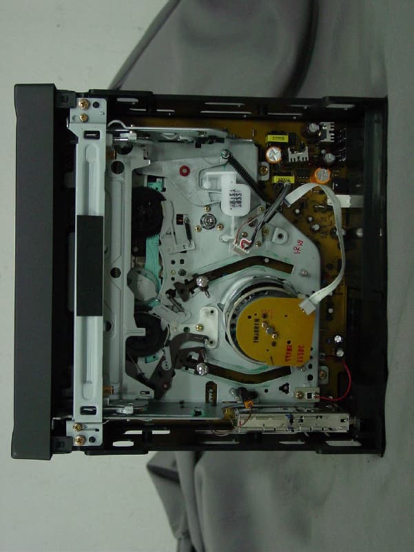
Click to zoom
Application Details
- Equipment Class
- HID - Part 15 TV Interface Device
- Date of Grant
- Apr 09, 2002
- Application Purpose
- Original Equipment
- Date of Application
- Apr 09, 2002
- Equipment Note
- Video Cassette Recorder
- Frequency Range
- 67.25000000 - 71.75000000
- Company
- Samjung Co Ltd
- Country
- South Korea
Documents & Files
Document Text
Text extracted from the exhibit documents filed with the FCC. Open a document above to read the original.
Users Manual
VIDEO CASSETTE RECORDER WITH TV TUNER User's Guide CAUTIONS AND WARNINGS To obtain the best results and to avoid malfunctions, PLEASE READ CAREFULLY THE DESCRIPTIONS AND OPERATING PROCEDURES CONTAINED IN THIS OWNER'S MANUAL PRIOR TO OPERATING THE VIDEO CASSETTE RECORDER. WARNINGTO PREVENT FIRE OR ELECTRIC SHOCK, DO NOT EXPOSE THIS APPLIANCE TO RAIN OR MOISTURE. Indicates a warning or notice regarding product operation. Indicates the presence of important operating and maintenance (servicing) instructions. RISK OF ELECTRIC SHOCKS DO NOT OPEN CAUTIONTO REDUCE THE RISK OF ELECTRIC SHOCK, DO NOT REMOVE THE COVER. NO USER-SERVICEABLE PARTS INSIDE. REFER SERVICING TO QUALIFIED SERVICE PERSONNEL. CAUTION AVERTISSEMENTPOUR PREVENIR LES RISQUES D'INCENDIE ET D'ELECTROCUTION, NE PAS EXPOSER CET APPAREIL A LA PLUIE NI A L'HUMIDITE. This user manual employs the following symbols to indicate different types of warning messages. Indicates the presence of uninsulated dangerous voltage within the unit enclosure. ' ' ' ' ' 1 2 1. Read Instructions-All the safety and operating instructions should be read before the Video Cassette Recorder is operated. 2. Retain Instructions- The safety and operating instructions should be retained for future reference. 3. Heed Cautions and Warnings-All cautions and warnings regarding the Video Cassette Recorder should be adhered to. 4. Follow Instructions-All operating instructions should be followed. 5. Cleaning-Unplug or turn off vehicle power to the Video Cassette Recorder before cleaning. Do not use liquid cleaners or aerosol cleaners. Use only a damp cloth for cleaning. 6. Attachments-Do not use attachments not recommended by the Video Cassette Recorder manufacturer as they may cause hazards. 7. Water and Moisture-Do not use this video product near water, for example, near a bath tub, kitchen sink, near a swimming pool or other wet locations. 8. Accessories-Do not place the Video Cassette Recorder on an unstable cart, stand, tripod, bracket, or table. The Video Cassette Recorder may fall, causing serious injury to a child or adult, and serious damage to the Video Cassette Recorder. Use only with a cart,stand, tripod, bracket, or table recommended by the manufacturer or sold with the Video Cassette Recorder. When used in vehicles, the Video Cassette Recorder must be securely fastened. 9. Ventilation-Slots and openings in the cabinet are provided for ventilation to ensure reliable operation of the Video Cassette Recorder and to protect it from overheating. These openings must not be blocked or covered. The openings should never be blocked by placing the Video Cassette Recorder on a bed, sofa, rug, or other similar surface. The Video Cassette Recorder should never be placed near or over a radiator or heat register. This video product should not be placed in a built-in installation such as a book case or rack unless proper ventilation is provided. 10. Power Sources-The Video Cassette Recorder should be operated only from the type of power source indicated on the marking label. If you are not sure of the type of power supply to your home, consult your appliance dealer or local power company. For video products intended to operate from battery power or other sources, refer to the operating instructions. Servicing Do not attempt to service the set yourself as opening or removing covers may expose you to dangerous voltage or other hazards. Refer all servicing to qualified service personnel. Replacement of parts When replacement of parts is required, be sure the service technician has used replacement parts specified by the manufacturer that have the same characteristics as the original parts. Unauthorised substitutions may result in fire, electric shock, or other hazards. Safety Check Upon completion of any service or repairs to the set, ask the service technician to perform routine safety checks (as specified by the manufacturer) to determine that the set is in safe operating condition. SAFETY INSTRUCTIONS 3 CAUTIONS AND WARNINGS SAFETY INSTRUCTIONS TABLE OF CONTENTS VIDEO HEAD CLEANING FEATURES CONTROLS AND INDICATORS REAR PANEL REMOTE CONTROLLER ERASURE PROTECTION BASIC PLAYBACK OSD(ON SCREEN DISPLAY) TROUBLESHOOTING SPECIFICATION 1 2 3 4 4 5 6 8 9 9 10 14 16 TABLE OF CONTENTS INFORMATION TO THE USER This equipment has been tested and found to comply with the limits for a Class B digital device, pursuant to part 15 of the FCC Rules. These limits are designed to provide reasonable protection against harmful interference in a residential installation. This equipment generates, uses and can radiate radio frequency energy and, if not installed and used in accordance with the instructions, may cause harmful interference to radio communications. However, there is no guarantee that interference will not occur in a particular installation. If this equipment does cause harmful interfere nce to radio or television reception, which can be determined by turning the equipment off and on, the user is encouraged to try to correct the interference by one more of the following measures: - Reorient or relocate the receiving antenna. - Increase the separation between the equipment and receiver. - Connect the equipment into an outlet on a circuit different from that to which the receiver is connected. - Consult the dealer or an experienced radio/TV technician for help. WARNING Changes or modifications not expressly approved by the manufacturer could void the user’s authority to operate the equipment. 3 The video heads enable the VCR to read video information pictures from the tape during playback. In the unlikely event that the heads become clogged with dirt video playback will be impossible. This can easily be determined during playback of a known good tape, there is good sound, but the picture is extremely snowy. If this is the case, have the video cassette recorder checked by qualified service personnel. NOTES During normal operation of the VCR, the video and audio heads can accumulate di…
Text truncated - open the document above for the full version.
Block Diagram
RF TUNER ANT I N RF OUT A/V OUT A/V I C CHI P 3.5795M Hz DC12V I NPUT POW ER LOGI C KEY / FUNCTI ON Mi COM I C CHI P 14.318M Hz Hi - Fi I C CHI P A/V I N, OUTPUT AUDI O OUT A/V I N Block Diagram Model : SVR-N404FCC IC : NPESVRN001Date : 2002-04-02
External Photos
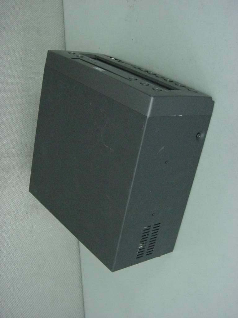
FCC ID. : NPESVRN001 File No. : E024R-008 ONETECH Testing & Evaluation Lab. [ Front View of the EUT ] FCC ID. : NPESVRN001 File No. : E024R-008 ONETECH Testing & Evaluation Lab. [ Rear View of the EUT ] FCC ID. : NPESVRN001 File No. : E024R-008 ONETECH Testing & Evaluation Lab. [ Inside View after Cover Open ]
ID Label/Location Info
FCC ID. : NPESVRN001 File No. : E024R-008 ONETECH Testing & Evaluation Lab. IDENTIFICATION LABEL: PROPOSED FCC ID LABEL The label included following statement will be attached on the rear side of product. This device complies with Part 15 of the FCC Rules. Operation is subject to the following two conditions: (1) this device may not cause harmful interference, and (2) this device must accept any interference received, including interference that may cause undesired operations. Made in Korea FCC ID : NPESVRN001 FCC ID
Internal Photos
FCC ID. : NPESVRN001 File No. : E024R-008 ONETECH Testing & Evaluation Lab. [ Inside View of the EUT ] FCC ID. : NPESVRN001 File No. : E024R-008 ONETECH Testing & Evaluation Lab. [ Top View of the Main Board ] FCC ID. : NPESVRN001 File No. : E024R-008 ONETECH Testing & Evaluation Lab. [ Bottom View of the Main Board ] FCC ID. : NPESVRN001 File No. : E024R-008 ONETECH Testing & Evaluation Lab. [ Top View of the TV Tuner Board ] FCC ID. : NPESVRN001 File No. : E024R-008 ONETECH Testing & Evaluation Lab. [ Bottom View of the TV Tuner Board ]
Test Report
Page 1 of 14 FCC ID. : NPESVRN001 File No. : E024R-008 This report shall not be reproduced except in full without our written approval. EMC-004 (Rev.0) HEAD OFFICE : #505 SK APT. Factory 223-28, Sangdaewon 1 Dong, Jungwon-Gu, Seongnam-City, Kyunggi-Do, 462-121, Korea (TEL: +82-31-746-8500, FAX: +82-31-746-8700) EMC Testing Dept : 426-1 Daessangryung-Ri, Chowol-Myun, Kwangju-Si, Kyounggi-Do, 464-860, Korea. (TEL: +82-31-765-8289 FAX: +82-31-766-2904) ONETECH Testing & Evaluation Lab. ELECTROMAGNETIC EMISSION COMPLIANCE REPORT FOR FCC CLASS B CERTIFICATION Test report file number : E024R-008 Applicant : SAMJUNG Co., Ltd. Address : 152-78 Hwanggye-Ri, Taean-Eup, Hwasung-Si, Kyounggi-Do, 445-977, Korea Manufacturer : SAMJUNG Co., Ltd. Address : 152-78 Hwanggye-Ri, Taean-Eup, Hwasung-Si, Kyounggi-Do, 445-977, Korea Type of Equipment : CAR VIDEO CASSETTE RECORDER FCC ID. : NPESVRN001 Model / Type No. : SVR-N404 Serial number : N/A Total page of Report : 14 pages (including this page) Date of Incoming : March 28, 2002 Date of issue : April 2, 2002 SUMMARY The equipment complies with the regulation; FCC CFR 47 PART 15 SUBPART B, Class B. This test report contains only the result of a single test of the sample supplied for the examination. It is not a generally valid assessment of the features of the respective products of the mass-production. Prepared by: Reviewed by: Y. K. Nam / Assist. Chief Engineer Y. K. Kwon / Chief Manager EMC Dept. EMC Dept. ONETECH Corp. ONETECH Corp. Page 2 of 14 FCC ID. : NPESVRN001 File No. : E024R-008 This report shall not be reproduced except in full without our written approval. EMC-004 (Rev.0) HEAD OFFICE : #505 SK APT. Factory 223-28, Sangdaewon 1 Dong, Jungwon-Gu, Seongnam-City, Kyunggi-Do, 462-121, Korea (TEL: +82-31-746-8500, FAX: +82-31-746-8700) EMC Testing Dept : 426-1 Daessangryung-Ri, Chowol-Myun, Kwangju-Si, Kyounggi-Do, 464-860, Korea. (TEL: +82-31-765-8289 FAX: +82-31-766-2904) ONETECH Testing & Evaluation Lab. CONTENTS Page 1. VERIFICATION OF COMPLIANCE...............................................................................................................................3 2. GENERAL INFORMATION.................................................................................................................................................4 2.1 PRODUCT DESCRIPTION............................................................................................................................................................4 2.2 RELATED SUBMITTAL(S) / GRANT(S).................................................................................................................................4 2.3 TEST SYSTEM DETAILS..............................................................................................................................................................5 2.4 TEST METHODOLOGY.................................................................................................................................................................5 2.5 TEST FACILITY..............................................................................................................................................................................5 3. SYSTEM TEST CONFIGURATION.................................................................................................................................5 3.1 JUSTIFICATION..............................................................................................................................................................................5 3.2 EUT EXERCISE SOFTWARE......................................................................................................................................................6 3.3 CABLE DESCRIPTION..................................................................................................................................................................6 3.4 NOISE SUPPRESSION PARTS ON CABLE...............................................................................................................................6 3.5 EQUIPMENT MODIFICATIONS.................................................................................................................................................6 3.6 CONFIGURATION OF TEST SYSTEM.......................................................................................................................................7 3.6.1 Line Conducted Test :..............................................................................................................................................................7 3.6.2 Radiated Emission Test...........................................................................................................................................................7 3.6.3 Output Signal Level Test.........................................................................................................................................................7 3.6.4 Output Terminal Conducted Spurious Emission test........................................................................................................7 3.6.5 Transfer Switch Isolation Test...............................................................................................................................................8 4. PRELIMINARY TEST...............................................................................................................................................................8 4.1 AC POWER LINE CONDUCTED EMISSION TEST...............................................................................................................8 4.2 RADIATED EMISSIONS TESTS.................................................................................................................................................8 5. FINAL RESULT OF MEASURMENT..................................................................................................................…
Text truncated - open the document above for the full version.
Contact Information
Applicant
Jeong Won Shin(Sales Manager)
Test Firm
ONETECH Corp.Y. Kwon
Technical Specifications
| # | Rule Parts | Frequency Range | Power Output |
|---|---|---|---|
| 2 | 15B | 67.25 MHz - 71.75 MHz | - |
Other Applications from Samjung Co Ltd
NPESVDN002
Oct 30, 2002DVD/VCR Combo
Equipment Class
HID - Part 15 TV Interface Device