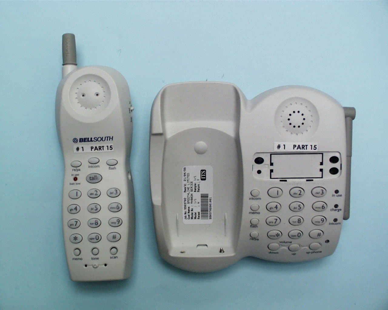
NQL9850900MHz Cordless Phone
Greatsino Electronic Limited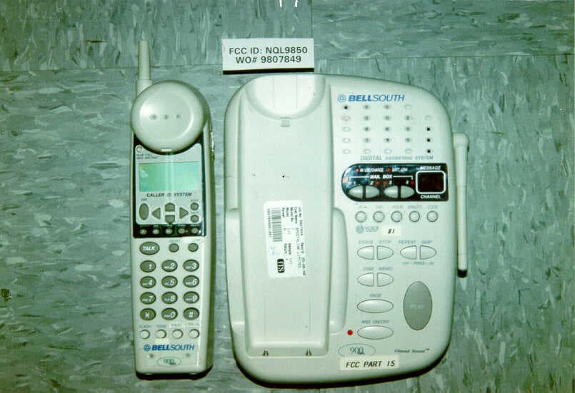
Click to zoom
Application Details
- Equipment Class
- DXT - Part 15 Low Power Transceiver, Rx Verified
- Date of Grant
- Nov 16, 1998
- Application Purpose
- Original Equipment
- Date of Application
- Oct 14, 1998
- Equipment Note
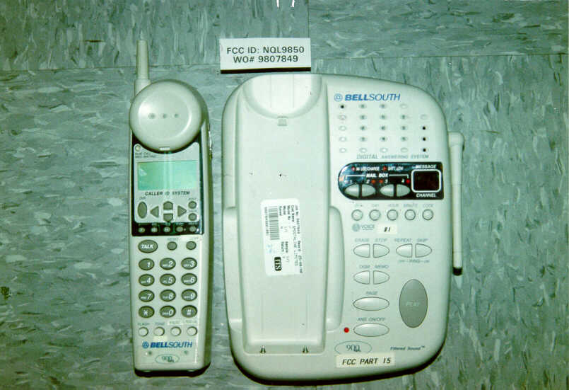
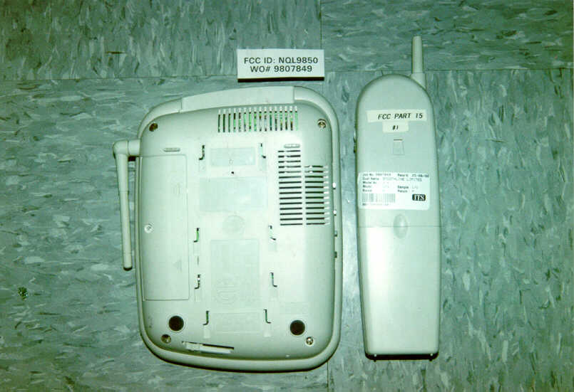
- 900MHz Cordless Phone
- Frequency Range
- 926.12000000 - 927.29000000
- Company
- Greatsino Electronic Limited
- Country
- Hong Kong
Documents & Files
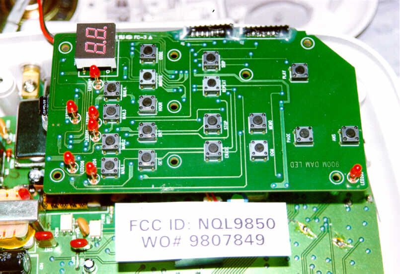
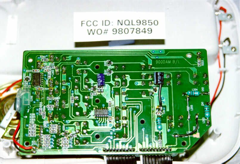
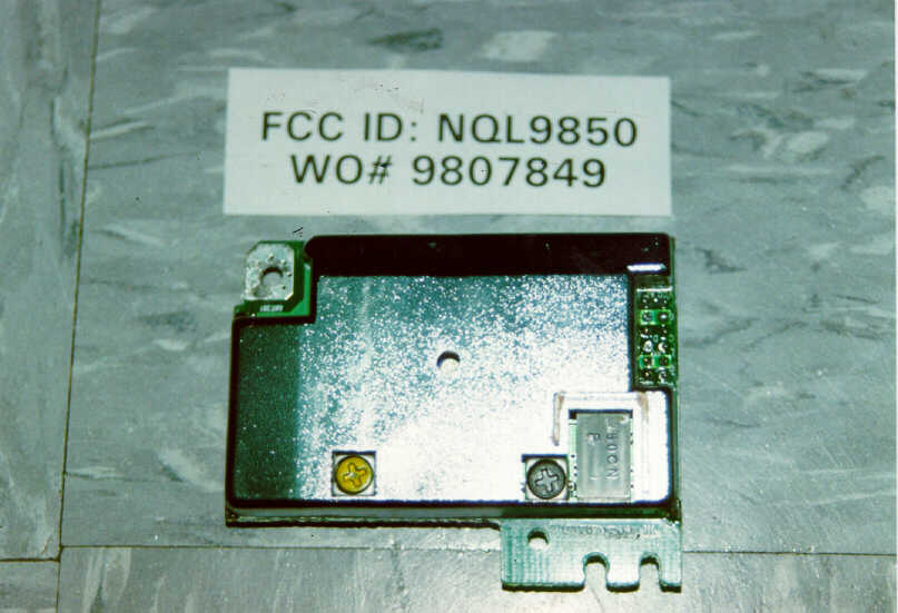
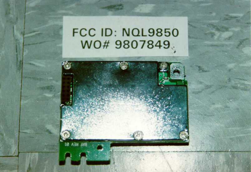
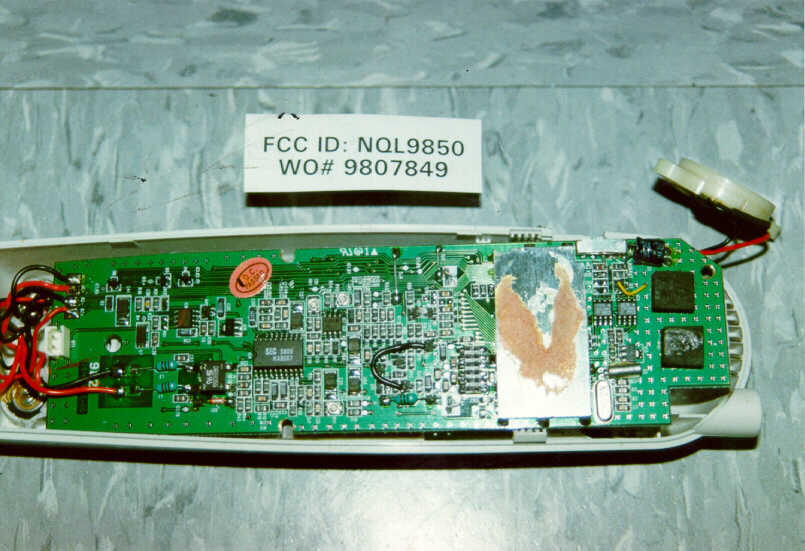
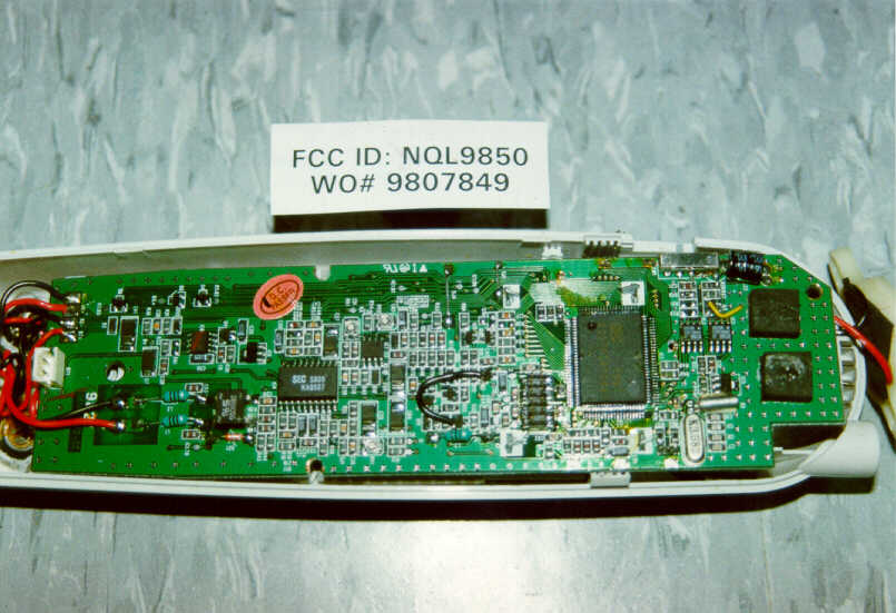
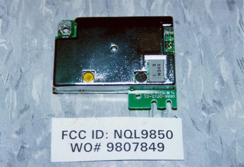
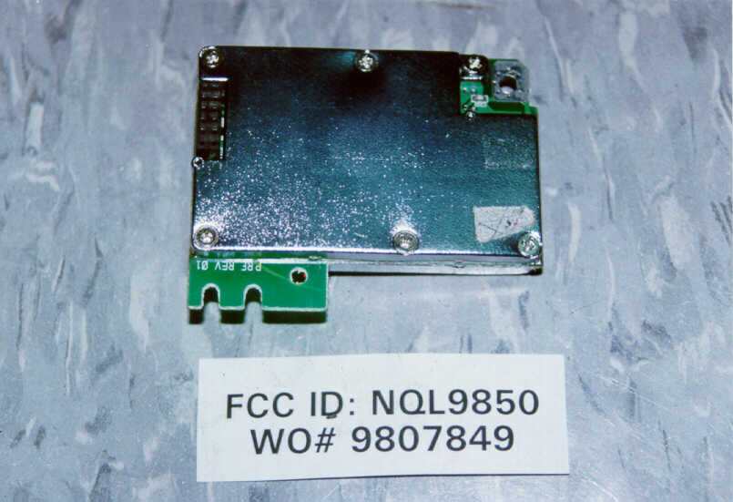
Document Text
Text extracted from the exhibit documents filed with the FCC. Open a document above to read the original.
Users Manual
1 Contents Safety Instructions .............................................................................................................4 HANDSET Controls - Location and Function .................................................................... 7 BASE UNIT Controls - Location and Function ................................................................... 11 Getting Started ................................................................................................................... 15 Desk Mounting ...................................................................................................................17 Wall Mounting .................................................................................................................... 18 Cordless Telephone Operation .......................................................................................... 19 Preparing for Use ......................................................................................................... 19 Turning the BASE UNIT RINGER ON/OFF ................................................................. 19 Receiving Calls ............................................................................................................ 20 Placing Calls ................................................................................................................ 21 HANDSET Redial Feature ........................................................................................... 21 Storing Numbers .......................................................................................................... 22 Recalling Stored Numbers from Memory .................................................................... 23 Extension Telephones ................................................................................................. 23 Caller ID System Operation ............................................................................................... 24 Caller ID System .......................................................................................................... 24 Viewing Caller Information During Incoming Calls ................................................ 24 Message Waiting ................................................................................................... 24 Caller ID on Call Waiting ........................................................................................ 25 Caller List .....................................................................................................................25 Viewing the Caller List ........................................................................................... 25 Placing a Call from the Caller List ......................................................................... 26 Editing the Caller List before Dialing ..................................................................... 26 Saving the Name and Number in the Caller List into the Directory ....................... 26 Deleting All Records in the Caller List ................................................................... 27 Selective Deleting in the Caller List ....................................................................... 27 2 Contents Name and Telephone Number Directory ..................................................................... 27 Viewing the Directory ............................................................................................. 27 Speed Viewing the Directory ................................................................................. 27 Saving in the Directory ........................................................................................... 28 Preferred Calls ....................................................................................................... 28 Blocked Calls ......................................................................................................... 28 Editing Name and Number in the Directory ........................................................... 29 Editing the Number in the Directory before Dialing ............................................... 30 Placing Calls from the Directory ............................................................................ 31 Deleting All Records in the Directory ..................................................................... 31 Selective Deleting in the Directory ......................................................................... 31 Function Operation ...................................................................................................... 32 A. Language .......................................................................................................... 33 B. Silent ON/OFF .................................................................................................. 33 C. Time Set ............................................................................................................ 33 D. Ringer Volume .................................................................................................. 34 E. Contrast ............................................................................................................ 34 F. PBX Number ..................................................................................................... 34 G. PBX Mode ......................................................................................................... 35 H. Pause Time ....................................................................................................... 35 I. MSG Waiting (Message Waiting) ...................................................................... 35 Telephone Keypad Characters .................................................................................... 36 Answering System Operation ............................................................................................ 37 Setting the Day/Time Stamp .................................…
Text truncated - open the document above for the full version.
Block Diagram
Handset Block Diagram Base unit Block Diagram
Operational Description
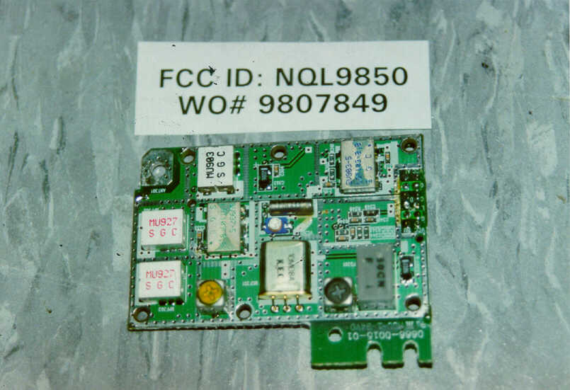
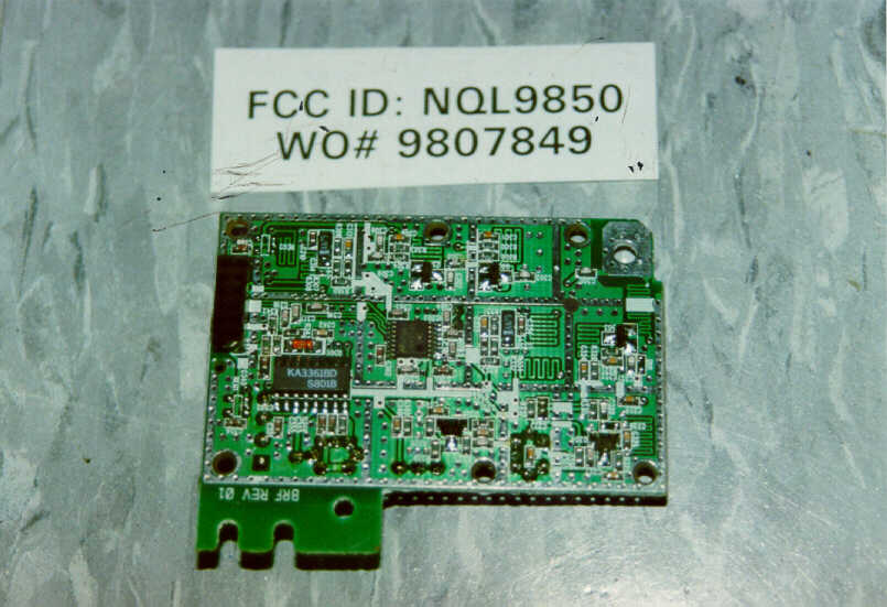
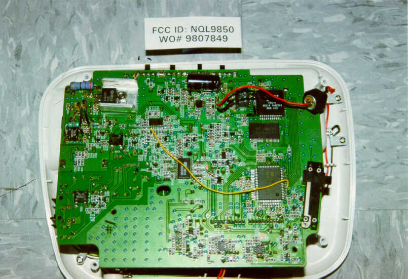
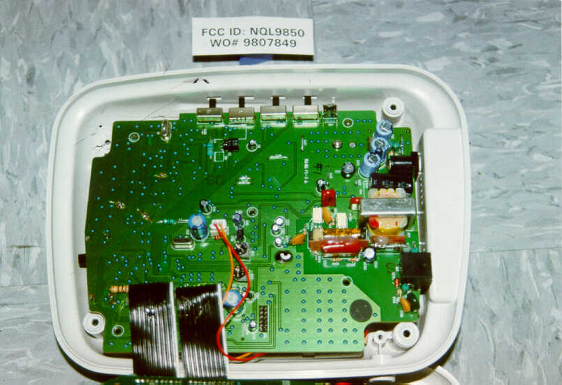
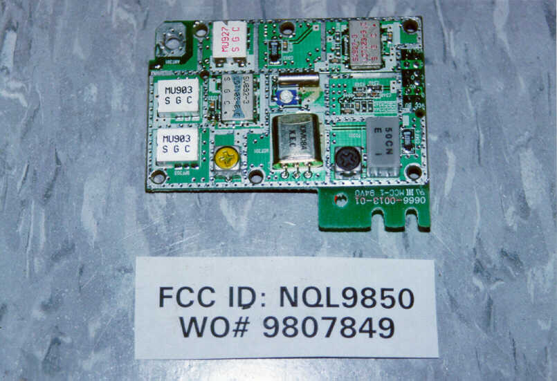
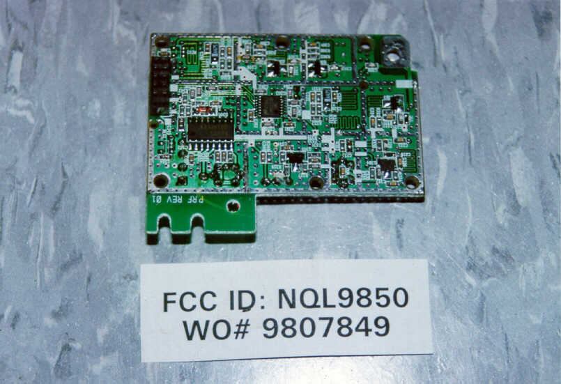
MODEL NUMBER ALLOCATION Presently, we have a large number of models within each of our various model number series of cordless telephones. Our clients continually request slightly different cosmetic variations of each registered model such as a different case color . In order to control all of these permutations, it is constantly necessary to assign and file, with the FCC, new model numbers to cover these cosmetic variations. Since all models, within a series of cordless telephones, are electrically and functionally identical, varying only in cosmetic detail and to avoid the need to constantly file, with the FCC, to register additional model numbers for cosmetic purposes, we request to register our models as listed tradenames and model numbers: TRADENAMESMODEL NUMBERS BELLSOUTHMH9930(0)(Y)MH9935(0)(Y) AMERITECHMH9931(0)(Y)MH9936(0)(Y) BELL ATLANTICMH9932(0)(Y)MH9937(0)(Y) PACIFIC BELLMH9933(0)(Y)MH9938(0)(Y) UNISONICMH9934(0)(Y)MH9939(0)(Y) MH9930 series are 900Mhz Cordless Telephone , Caller ID with Digital Answering Machine NOTE :(0) Zero=Additional charger base suffix "Y" can be added to the model number to represent color variation, can be any letter/s of the alphabet as follows (but not limited to this list) such as : "No suffix"=Gray case B/BK=Black case HG/VHG=Green case W=White case R=Red case RB=Red/Black case PL=Pearl white case such that : MH9932-Model MH9932 is the standard model in gray case MH9932B-Model MH9932 in black case MH9932HG-Model MH9932 in green case CIRCUIT DESCRIPTION OF 9932 Date Aug. 25, 98 Page 1 of 5 1. H/S RF MODULE 1)RX PART The receiver front-end contains a band pass filter, an RF low noise amplifier, a BPF, a active transistor mixer, a monolithic crystal filter and 10.7MHz IF amplifier. Also it includes buffer amplifiers for the generation of local oscillator power. This front-end receivers an RF signal from the antenna. And RF signals within this fre- quency range is 902.12MHz ~ 903.29MHz pass through RF AMP (Q303) and band pass filter. After passing through the band pass filter, the signal is mixed within 1st local frequency from voltage controlled oscillator, The signal is amplified on the IF AMP transistor (Q301) and the signal pass through the monolithic crystal filter (10.7MHz) after the IF signal pass the MCF filter, the signal enter by the FM IF (intermediate frequency) IC. And the signal is mixed in the FM IF IC (MC3361). The signal pass through the ceramic filter (450KHz). The output signal in the FM IF IC streams from the AF-OUT terminal of the connector 1 to the base. 2) TX PART The signal is made to the portable, enter by the AF-IN terminal of the connector. The signal send the MOD terminal of the TX VCO. The signal is mixed in the TX VCO mixing the RF signal, the RF signal adjust the trimmer capacitor (VC301). The RF signal enter by the transmission power AMP transistor (Q304, Q305). The signal is amplitude in the Q304, Q305. Enter by the band pass filter. The RF signal pass through the band pass filter, towards the ANT. The last transmission RF signal is 926.12MHz ~ 927.29MHz. Date Aug. 25, 98 Page 2 of 5 2. HAND SET MAIN The demodulated signal, resulting from Double Super Heterodyne system, which appears at output Pin no.5 of CN1 is connected to Pin no.15 Expander input. The audio output from Pin no.19 is finally amplified by Q3 and a.c coupled to the receiver unit the HAC compatibility. The demodulated data code from CN1 Pin no.5 is fed to IC7B. Pin no.7 of IC7B is connected to (DATA IN) Pin no.54 of IC1. Voice signal from C-MIC is coupled to Pin no.8 of IC4A. The voice signal is compressed by IC4 & output Pin no.1 is connected to Pin no.11 of CN1 for modulation. Pin no.57 of IC1 is the output port for data code that should be transmitted to the base unit. This data code is connected to the Pin no.11 of CN1 for modulation. LCD display operation is monitored by Pin no.1~34, 62~77, 95~100 of IC1. During the charging, it is detected by Pin no.51 of IC1. Key board operation is monitored by Pin no.78~85 of IC1. Key Tone and the ringing from Pin no.89,90 of IC1 drives the BUZZER. Date Aug. 25, 98 Page 3 of 5 3. BASE RF MODULE 1)RX PART The receiver front-end contains a band pass filter, an RF low noise amplifier, a band pass filter, a active transistor mixer, a monolithic crystal filter and 10.7MHz IF amplifier. Also it includes buffer amplifiers for the generation of local oscillator power. This front-end receivers an RF signal from the antenna. And RF signals within this fre- quency range is 926.12MHz ~ 927.29MHz pass through RF AMP (Q303) and band pass filter, saw filter.. After passing through the band pass filter and saw filter, the signal is mixed within 1st local frequency from voltage controlled oscillator, The signal is amplified on the IF AMP tran- sistor (Q305) and the signal pass through the monolithic crystal filter (10.7MHz) after the IF signal pass the MCF filter, the signal enter by the FM IF (intermediate frequency) IC. And the signal is mixed in the FM IF IC (MC3361). The signal pass through the ceramic filter (450KHz). The output signal in the FM IF IC streams from the AF-OUT terminal of the connector to the base. 2) TX PART The signal is made to the portable, enter by the AF-IN terminal of the connector. The signal send the MOD terminal of the TX VCO. The signal is mixed in the TX VCO mixing the RF signal, the RF signal adjust the trimmer capacitor (VC301). The RF signal enter by the transmission power AMP transistor (Q301, Q302). Enter by the band pass filter. The RF signal pass through the band pass filter, towards the ANT. The last transmission RF signal is 902.12MHz ~ 903.29MHz. Date Aug. 25, 98 Page 4 of 5 4. BASE MAIN The demodulated signal, resulting from Double Super Heterodyne system, which appears at output Pin no.5 of CN5 is sent to IC103 Pin no.15 Expansion. The expended audio signal is sent to the telephone line via hybrid Transformer HY1. The demodulated data code from CN1 Pin no.5 is generated by IC101A. It i…
Text truncated - open the document above for the full version.
Schematics
MH993x Base Main Schematic Diagram MH993x Answering Schematic Diagram MH993x Handset Schematic Diagram
Schematics
900 MHz Base unit RF Circuit Diagram 900 MHz Handset RF Circuit Diagram
Test Report
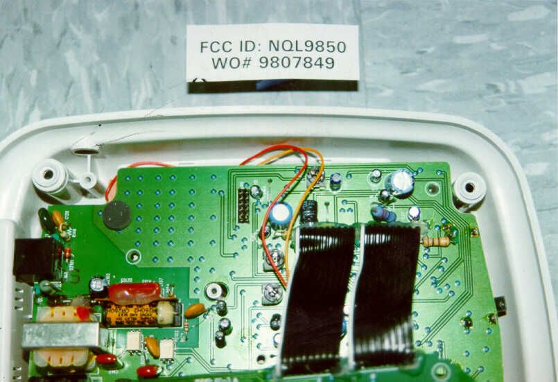
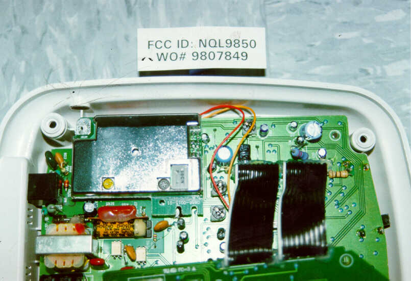
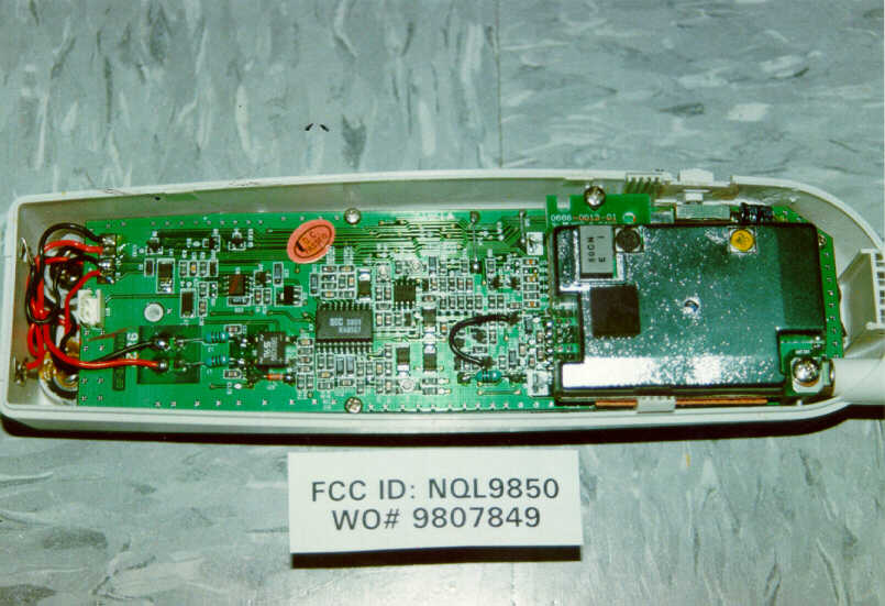
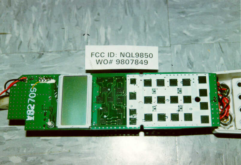
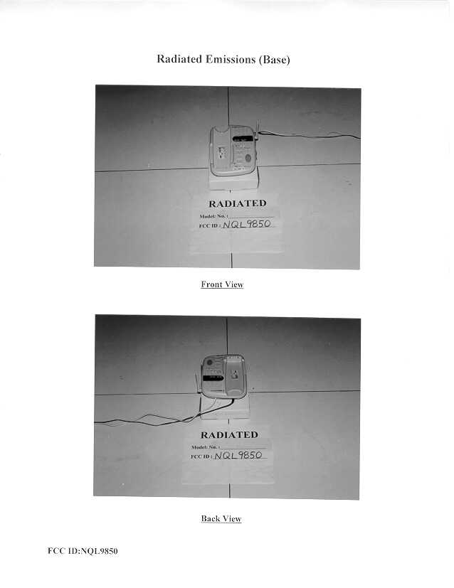
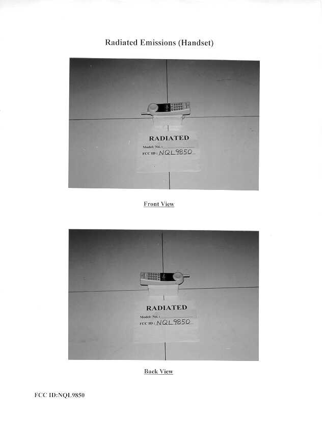
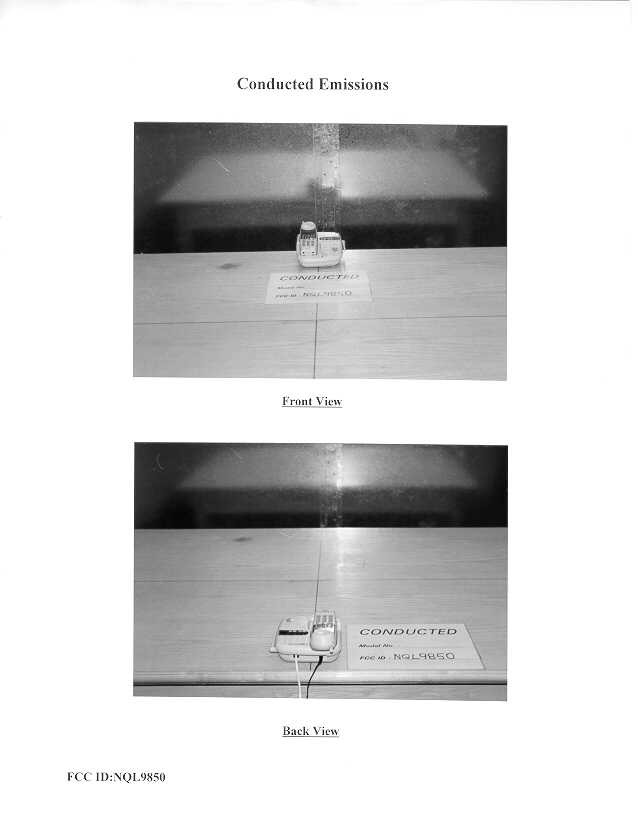
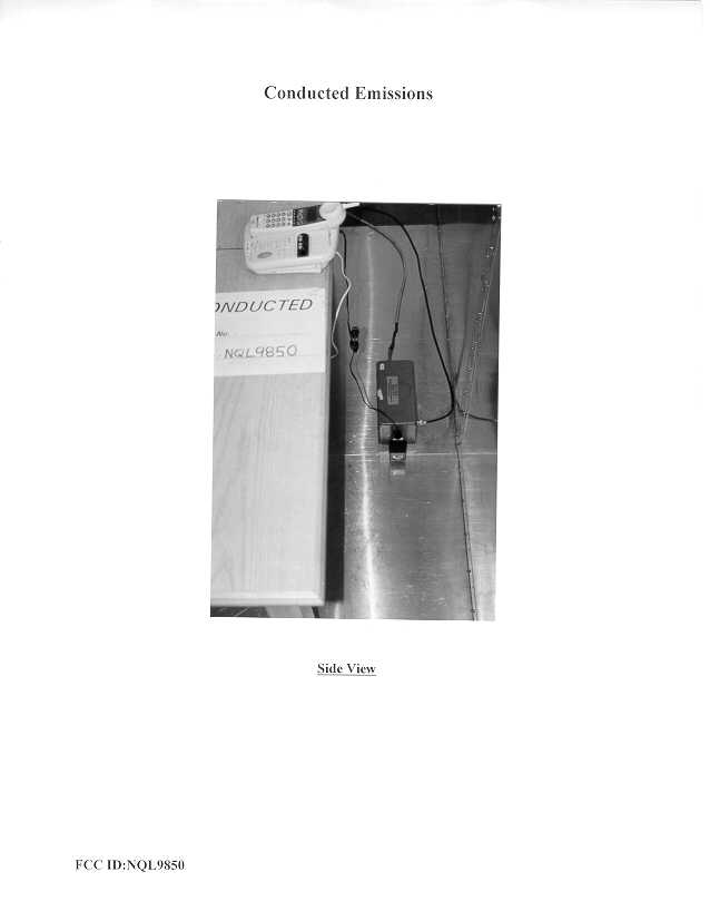
• The test results reported in this report shall refer only to the sample actually tested and shall not refer or be deemed to refer to bulk from which such a sample may be said to have been obtained. • This report shall not be reproduced except in full without prior authorization form Intertek Testing Services Limited FCC ID: NQL9850 Greatsino Limited Application For Certification 900MHz Cordless Telephone (FCC ID: NQL9850) WO# 9807849 CKL/at October 12, 1998 INTERTEK TESTING SERVICES FCC ID: NQL9850 i LIST OF EXHIBITS INTRODUCTION EXHIBIT 1:General Description EXHIBIT 2:System Test Configuration EXHIBIT 3:Emission Results EXHIBIT 4:Equipment Photographs EXHIBIT 5:Product Labelling EXHIBIT 6:Technical Specifications EXHIBIT 7:Instruction Manual EXHIBIT 8:Security Code Information INTERTEK TESTING SERVICES FCC ID: NQL9850 ii MEASUREMENT/TECHNICAL REPORT Greatsino Limited - MODEL: 9930 Series FCC ID: NQL9850 This report concerns (check one:)Original Grant X Class II Change Equipment Type: Low Power Transmitter (example: computer, modem, transmitter, etc.) Deferred grant requested per 47 CFR 0.457(d)(1)(ii)?Yes No X If yes, defer until : date Company Name agrees to notify the Commission by: date of the intended date of announcement of the product so that the grant can be issued on that date. Transition Rules Request per 15.37?Yes No X If no, assumed Part 15, Subpart C for intentional radiator - the new 47 CFR [10-1-96 Edition] provision. Report prepared by:C. K. Lam Intertek Testing Services. 2/F., Garment Centre, 576 Castle Peak Road, Kowloon, Hong Kong. Phone:852-2746-8211 Fax:852-2785-5487 INTERTEK TESTING SERVICES FCC ID: NQL9850 iii Table of Contents 1.0 General Description ................................................................................................................. 2 1.1 Product Description.............................................................................................................. 2 1.2 Related Submittal(s) Grants .................................................................................................3 1.3 Test Methodology ................................................................................................................ 3 1.4 Test Facility.......................................................................................................................... 3 2.0 System Test Configuration ...................................................................................................... 5 2.1 Justification .......................................................................................................................... 5 2.2 EUT Exercising Software.....................................................................................................5 2.3 Support Equipment List and Description.............................................................................. 6 2.4 Equipment Modification ......................................................................................................7 3.0 Emission Results ....................................................................................................................... 9 3.1 Field Strength Calculation ..................................................................................................10 3.2 Radiated Emission Configuration Photograph - Base Unit ................................................. 11 3.3 Radiated Emission Data - Base Unit.......................................................................................13 3.4 Radiated Emission Configuration Photograph - Handset.......................................................19 3.5 Radiated Emission Configuration Data - Handset .............................................................. 21 3.6 Radiated Emission on the bandedge ................................................................................... 22 3.7 Line Conducted Configuration Photograph - Base Unit..................................................... 25 3.8 Line Conducted Data - Base Unit ...........................................................................................28 4.0 Equipment Photographs ........................................................................................................ 28 5.0 Product Labelling ................................................................................................................... 30 6.0 Technical Specifications ......................................................................................................... 32 7.0 Instruction Manual ......................................................................................................................63 8.0 Security Code Information .........................................................................................................65 INTERTEK TESTING SERVICES FCC ID: NQL9850 iv List of attached file Exhibit typeFile Descriptionfilename Cover LetterLetter of Agencyletter.pdf Test ReportTest Reportreport.doc Operation DescriptionTechnical Descriptiondescrip.pdf Test Setup PhotoRadiated Emission for Basebase.jpg Test Setup PhotoRadiated Emission for Handsethandset.jpg Test ReportEmission Plotemission.pdf Test Setup PhotoConducted Emissionconduct1.jpg, conduct2.jpg Test ReportConducted Emission Test Resultconduct.pdf External PhotoExternal Photoophoto1.jpg, ophoto2.jpg Internal PhotoInternal Photoiphoto1.jpg to iphoto19.jpg Block DiagramBlock Diagramblock.pdf SchematicsCircuit Diagramcircuit.pdf, RFcircuit.pdf ID Label/LocationLabel Artwork and Locationlabel.pdf User ManualUser Manualmanual.pdf INTERTEK TESTING SERVICES FCC ID: NQL9850 1 EXHIBIT 1 GENERAL DESCRIPTION INTERTEK TESTING SERVICES FCC ID: NQL9850 2 1.0 General Description 1.1Product Description The equipment under test (EUT) is a 900 MHz cordless phone with answering machine and Caller ID/Call waiting with model number 9930 Series. The unit is capable of either tone or pulse dialing. The internal power supply's isolat…
Text truncated - open the document above for the full version.
Contact Information
Applicant
C Chan(Marketing Manager)
9-011-852-2736-8868Fax: 9-011-852-2730-5176
Technical Contact
Intertek Testing Services Hong Kong LtdC.K. Lam
[email protected](852)2746-8211
2/F., Garment Centre, · Kowloon · Hong Kong
Non-Technical Contact
Intertek Testing Services Hong Kong LtdC.K. Lam
[email protected](852)2746-8211
Test Firm
Intertek Testing Services Hong KongBilly Chow
Technical Specifications
| # | Rule Parts | Frequency Range | Power Output |
|---|---|---|---|
| 2 | - | 926.12 MHz - 927.29 MHz | - |
Other Applications from Greatsino Electronic Limited
NQL9960
Jun 27, 1999DXT - Part 15 Low Power Transceiver, Rx Verified
Equipment Class
DXT - Part 15 Low Power Transceiver, Rx Verified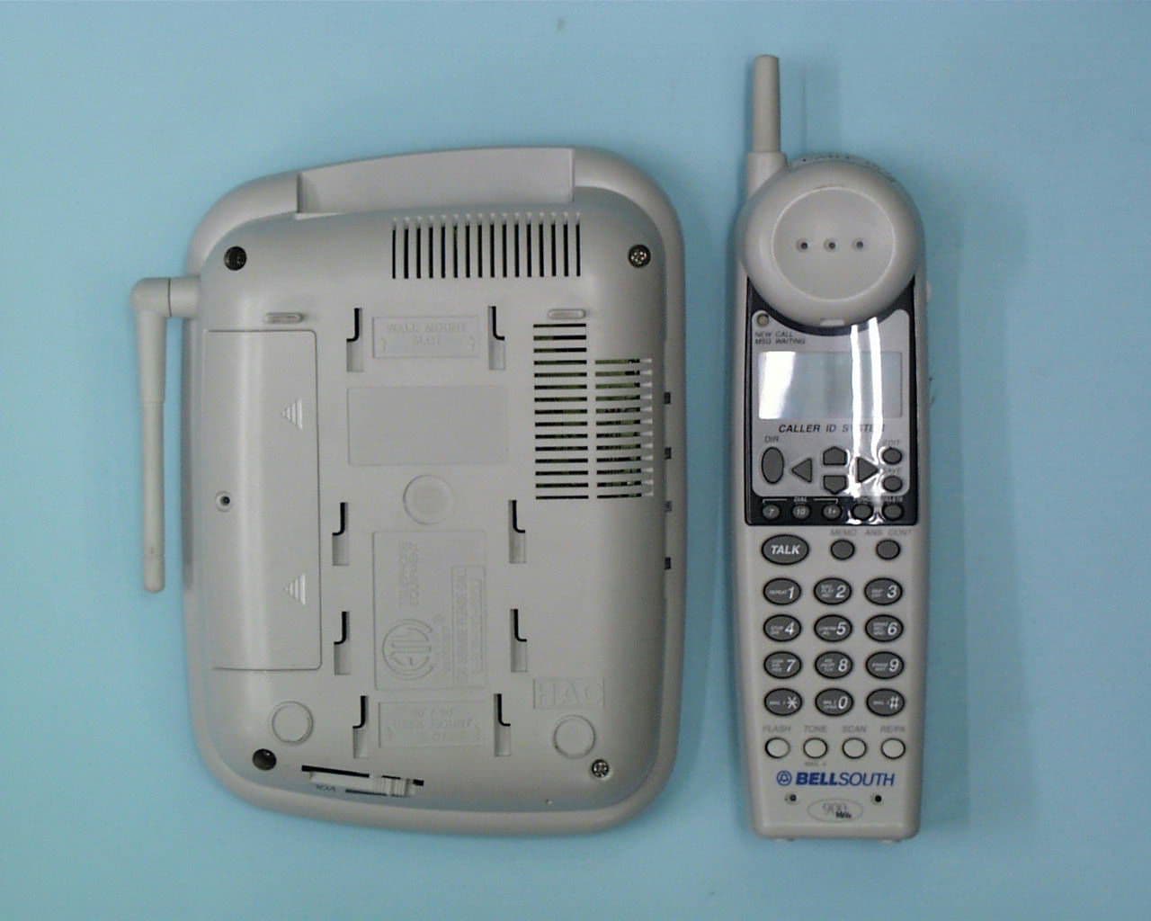
NQL9950
Apr 29, 1999900 MHz Cordless Telephone
Equipment Class
DXT - Part 15 Low Power Transceiver, Rx Verified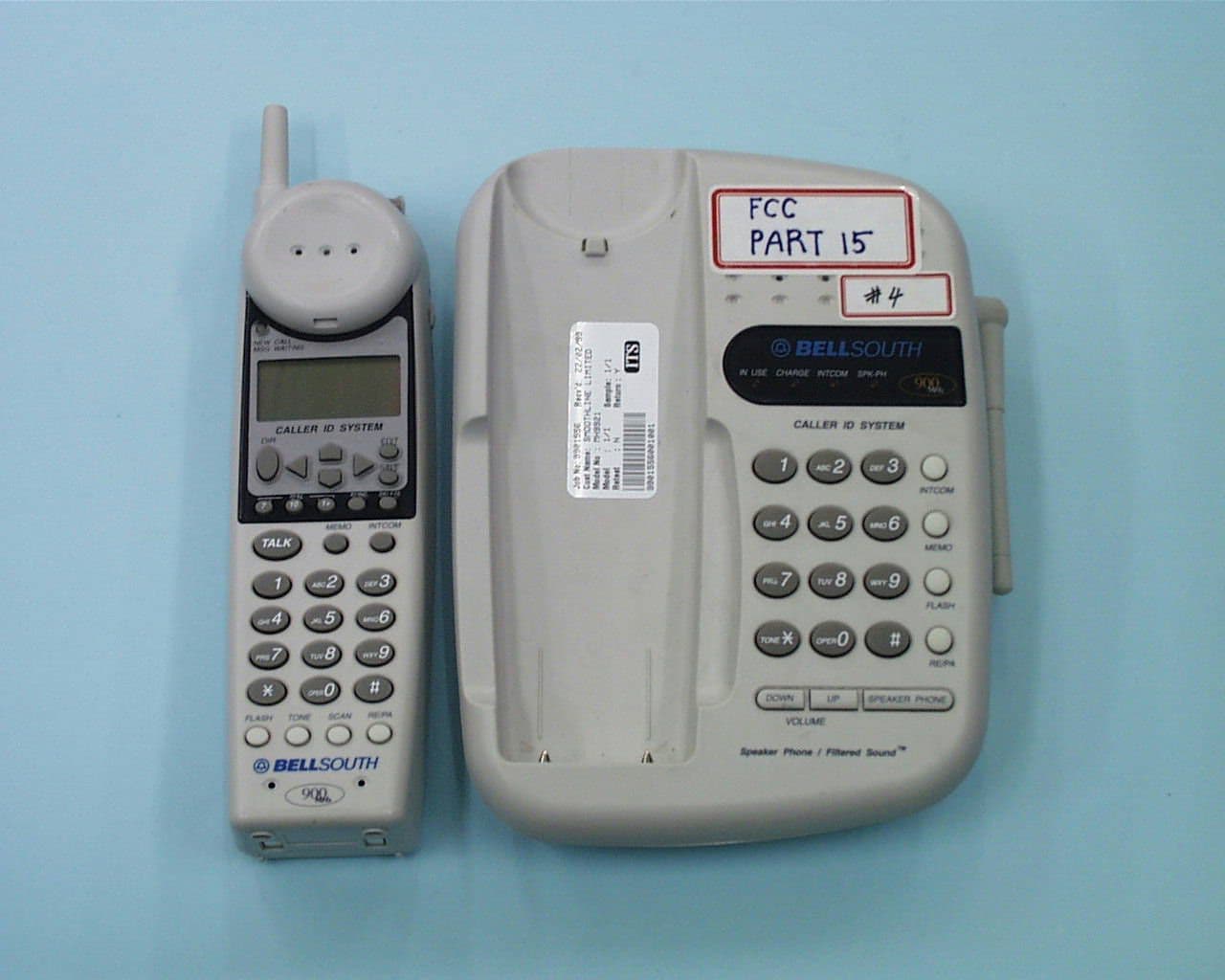
NQL9940
Apr 18, 1999DXT - Part 15 Low Power Transceiver, Rx Verified
Equipment Class
DXT - Part 15 Low Power Transceiver, Rx Verified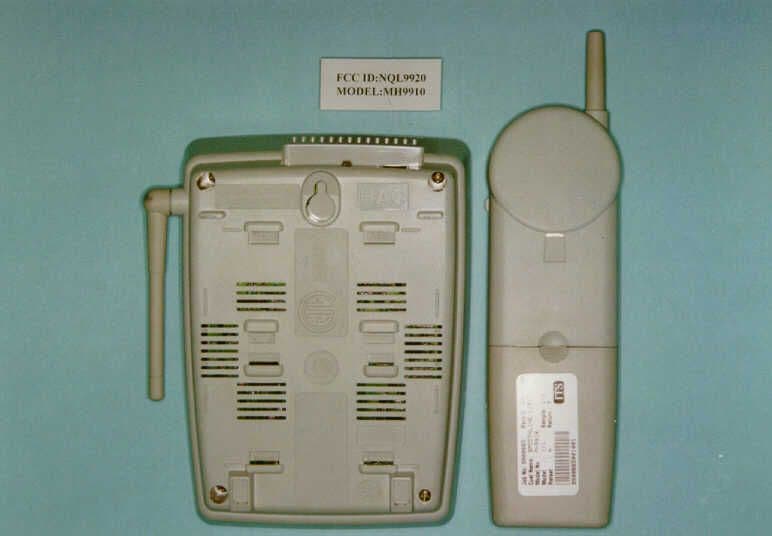
NQL9920
Mar 30, 1999DXT - Part 15 Low Power Transceiver, Rx Verified
Equipment Class
DXT - Part 15 Low Power Transceiver, Rx Verified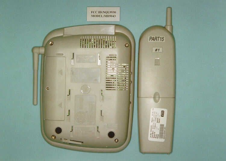
NQL9930
Mar 28, 1999DXT - Part 15 Low Power Transceiver, Rx Verified
Equipment Class
DXT - Part 15 Low Power Transceiver, Rx Verified