NQL9860900MHz Cordless phone
Greatsino Electronic Limited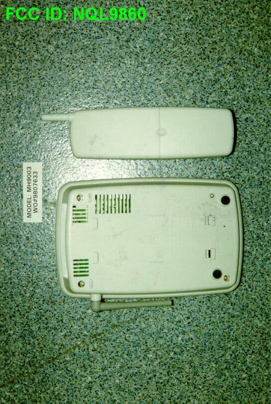
Click to zoom
Application Details
- Equipment Class
- DXT - Part 15 Low Power Transceiver, Rx Verified
- Date of Grant
- Oct 19, 1998
- Application Purpose
- Original Equipment
- Date of Application
- Aug 30, 1998
- Equipment Note
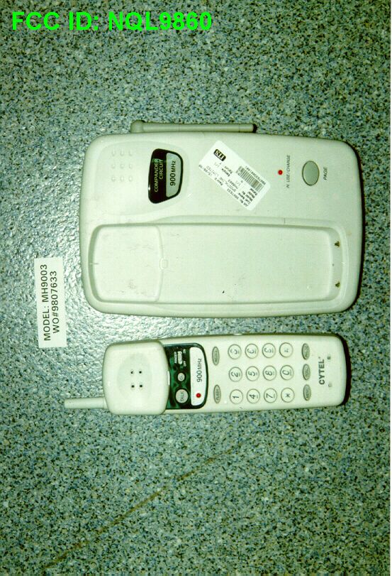
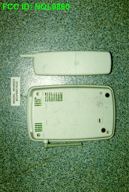
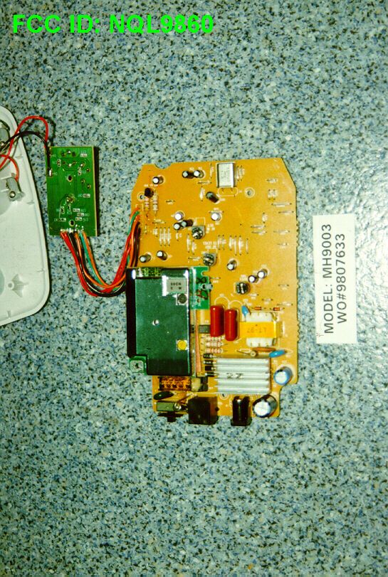
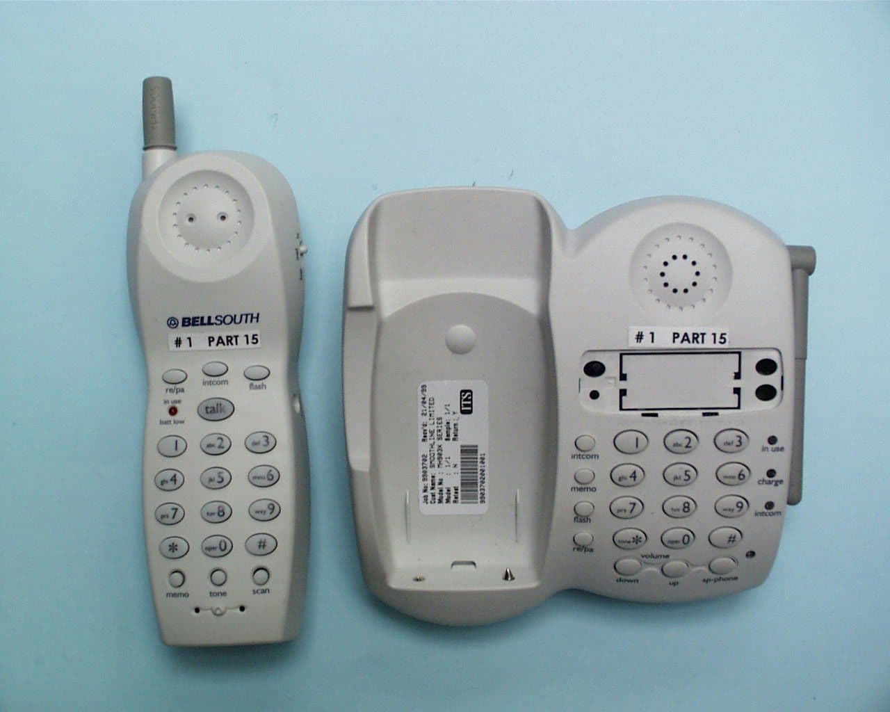
- 900MHz Cordless phone
- Frequency Range
- 926.12500000 - 927.10000000
- Company
- Greatsino Electronic Limited
- Country
- Hong Kong
Documents & Files

Document Text
Text extracted from the exhibit documents filed with the FCC. Open a document above to read the original.
Users Manual
CORDLESS TELEPHONE 40 CHANNEL AUTOSCAN Model 1900 OWNER'S MANUAL INSTALLATION AND OPERATING INSTRUCTIONS PLEASE READ THIS MANUAL CAREFULLY BEFORE USE. KEEP FOR YOUR REFERENCE. For Getting Started Information, please see Installation Instructions on page 8 or your separate Quick Start guide elcome to the family of CYTEL cordless telephone users. This CYTEL cordless telephone uses the latest technology to provide you with a high-performance communication tool. This telephone W is part of a comprehensive line of state-of-the-art communications instruments developed by CYTEL. Your telephone has been through rigorous testing, and its quality is guaranteed by CYTEL. When examining your new CYTEL cordless telephone, you will find an array of special features including: 40 Channel Autoscan - Push a button on the HANDSET to find and lock on to the clearest channel for any call. Telephone Number Storage - Store up to 10 frequently called numbers. Desk or Wall Mount - Use this equipment as a desk phone or as a wall phone. Tone or Pulse Dialing - Use this phone for either tone or push button pulse (rotary) dialing. Automated Functions - Redial the last number called, speed dial 10 numbers and automatic STANDBY. Security - Ensures greater privacy because a built-in security code with 65,536 combinations prevents use of your telephone line by another nearby cordless phone. Dependable Battery - Recharge your battery pack many times with the built-in charger. The warning tone tells you when the battery needs recharging. (see page 18.) Special Services - Use the FLASH button to access special services such as Call Waiting supplied by your telephone company or company switchboard. STANDBY Mode - When in STANDBY Mode, the phone is capable of receiving a call (ON HOOK). When the HANDSET is on the base it is automatically in the STANDBY Mode (ON HOOK). When the HANDSET is taken off the base it remains in the STANDBY Mode until you activate the TALK button. Battery Power Saver - Once fully charged, in STANDBY Mode and with the RINGER SWITCH in the "ON" position, the HANDSET can receive/send calls for a maximum of seven days without the need for recharging, depending on frequency of use. HANDSET Volume Level - Select the HANDSETvolume level (HI, MID, LOW). Special Features For Getting Started Information, please see Installation Instructions on page 8 or your separate Quick Start guide. Safety Instructions .............................................................................................. 2 HANDSET Controls - Location and Function....................................................... 4 BASE UNIT Controls - Location and Function ..................................................... 6 Getting Started ................................................................................................... 8 Wall Mounting ..................................................................................................... 10 Basic Operation .................................................................................................. 11 Receiving Calls ................................................................................................... 12 Placing Calls ....................................................................................................... 13 Storing Numbers ................................................................................................. 14 Recalling Stored Numbers .................................................................................. 15 Security.............................................................................................................. 16 Recharging the Battery Pack .............................................................................. 17 Changing the Battery Pack ................................................................................. 18 Problem Solving .................................................................................................. 19 Technical Information ......................................................................................... 21 FCC Requirements ............................................................................................. 22 Warranty Information .......................................................................................... 24 Wall Mount Template .......................................................................................... 26 Contents 1 IMPORTANT SAFETY INSTRUCTIONS To reduce the risk of fire, electric shock and/or injury, always follow these basic safety precautions when using your cordless telephone equipment. 1.Read and understand all instructions. 2.Follow all warnings and instructions marked on the telephone. 3.Unplug this telephone from the wall outlet before cleaning or replacing batteries. Do not use liquid cleaners or aerosol cleaners. Use a damp cloth for cleaning. If necessary, use only a mild soap. 4.Do not use this telephone near a bathtub, kitchen sink, wash bowl, laundry tub, swimming pool, in a wet basement, or anywhere else where there is water. 5.Do not place this telephone on an unstable cart, stand or table. A fall could cause serious damage to the phone. 6. This product should never be placed near or over a radiator or heat register. This product should not be placed in a built-in installation unless proper ventilation is provided. 7.Operate this telephone only with the correct electrical voltage shown on the marking label. If you are not sure of the voltage in your home, consult your dealer or local power company. 8.Do not allow anything to rest on the power cord. Do not install the phone where people will walk on the cord. 9.Do not overload wall outlets and extension cords. This can increase the risk of fire or electric shock. 10.Never push objects of any kind through slots in the phone. They could touch dangerous voltage points or short out parts that could result in a risk of fire or electric shock. Never spi…
Text truncated - open the document above for the full version.
Operational Description
MODEL NUMBER ALLOCATION Presently, we have a large number of models within each of our various model number series of cordless telephones. Our clients continually request slightly different cosmetic variations of each registered model such as a different case color . In order to control all of these permutations, it is constantly necessary to assign and file, with the FCC, new model numbers to cover these cosmetic variations. Since all models, within a series of cordless telephones, are electrically and functionally identical, varying only in cosmetic detail and to avoid the need to constantly file, with the FCC, to register additional model numbers for cosmetic purposes, we request to register our models as listed tradenames and model numbers: TRADENAMESMODEL NUMBERS BELLSOUTHD(HAC) MH9017(0)(Y) AMERITECHD(HAC) MH9018(0)(Y) BELL ATLANTICD(HAC) STC 1900(0)(Y) PACIFIC BELL D(HAC) MH9019(0)(Y) UNISONICD(HAC) MH9003(0)(Y) D(HAC) MH9101(0)(Y) * additional NOTE:(0) Zero=Additional charger base suffix "Y" can be added to the model number to represent color variation, can be any letter/s of the alphabet as follows (but not limited to this list) such as : "No suffix"=Gray case B/BK=Black case HG/VHG=Green case W=White case R=Red case RB=Red/Black case PL=Pearl white case such that : MH9017-Model MH9017 is the standard model in gray case MH9017B-Model MH9017 in black case MH9017HG-Model MH9017 in green case
Test Report
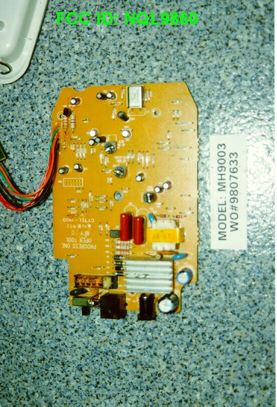
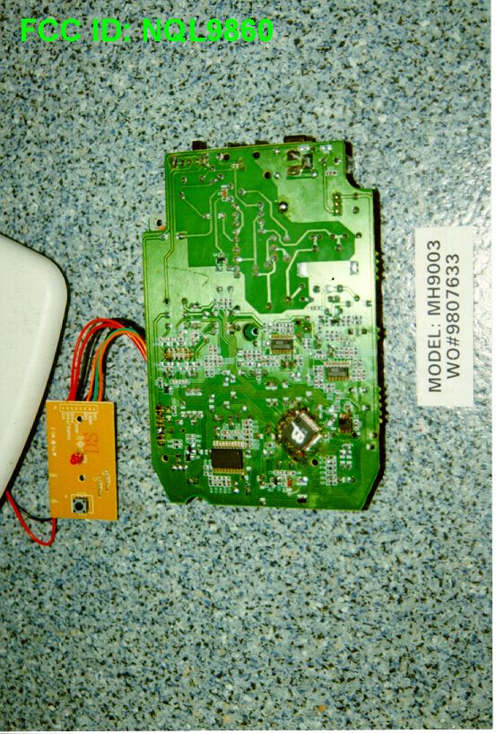
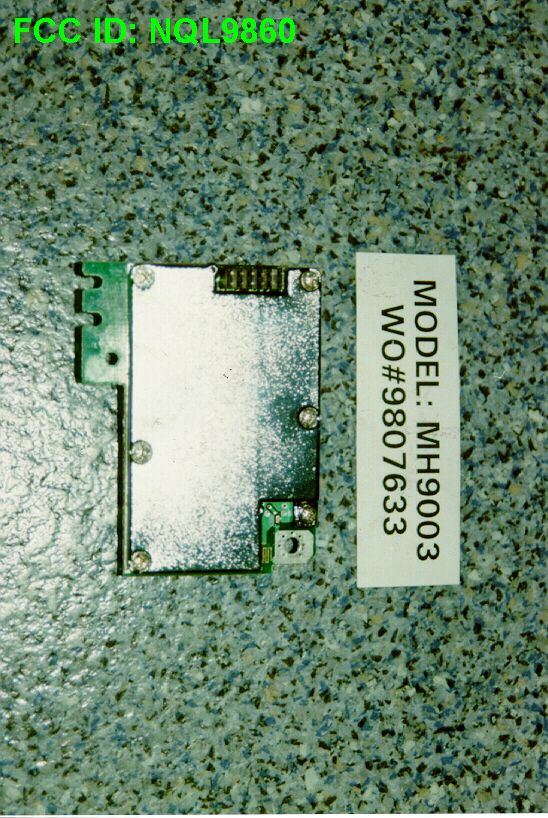
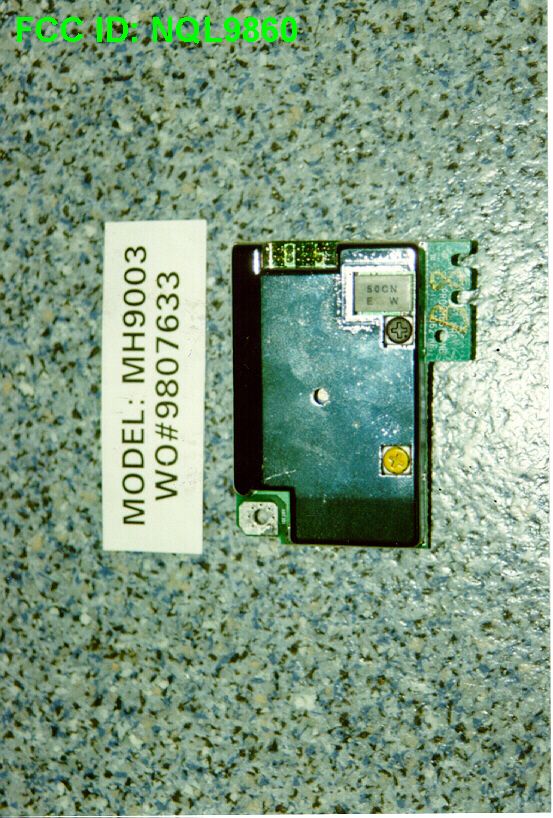
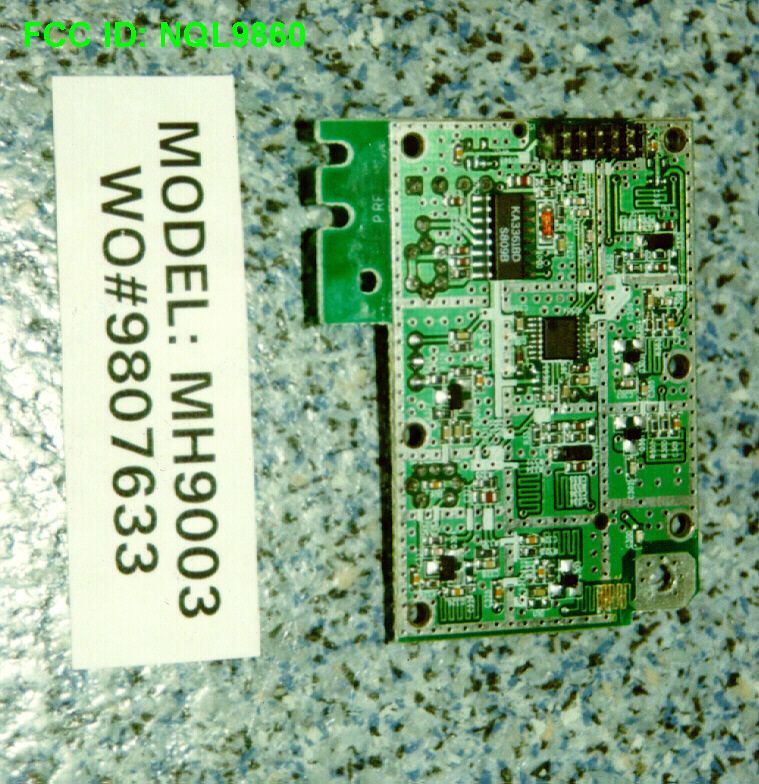
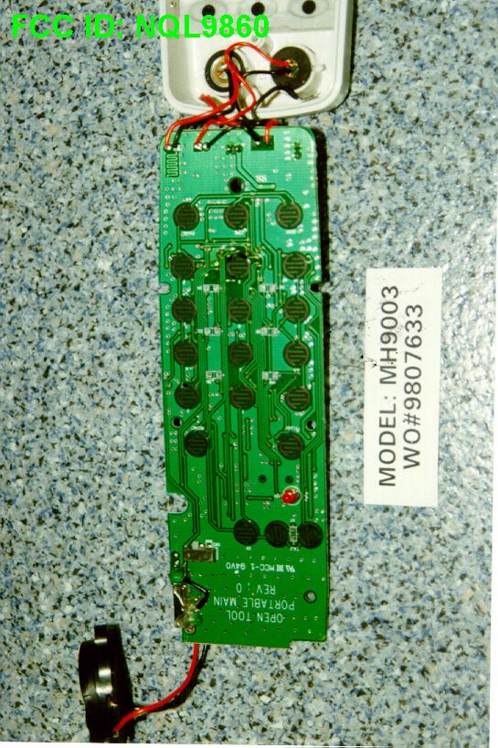
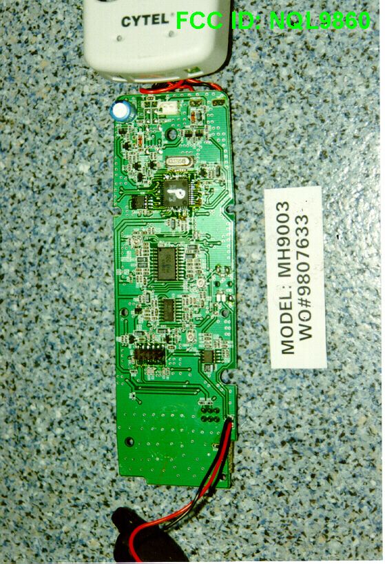
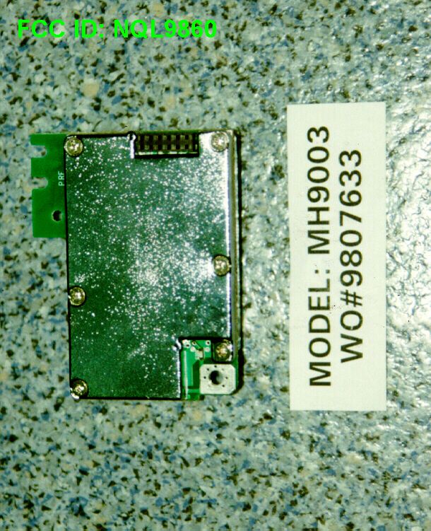
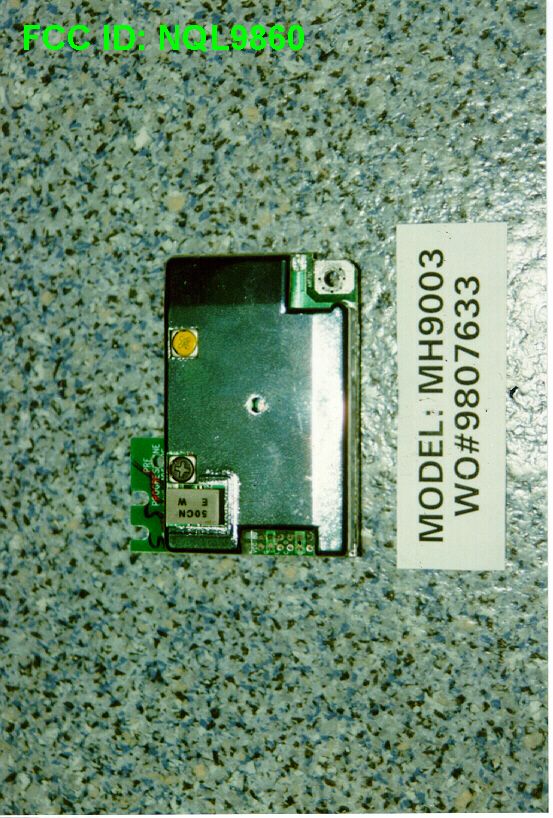
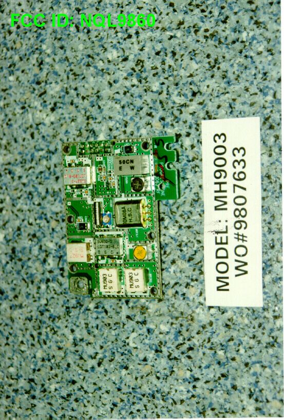
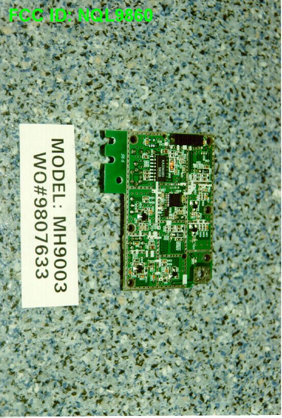
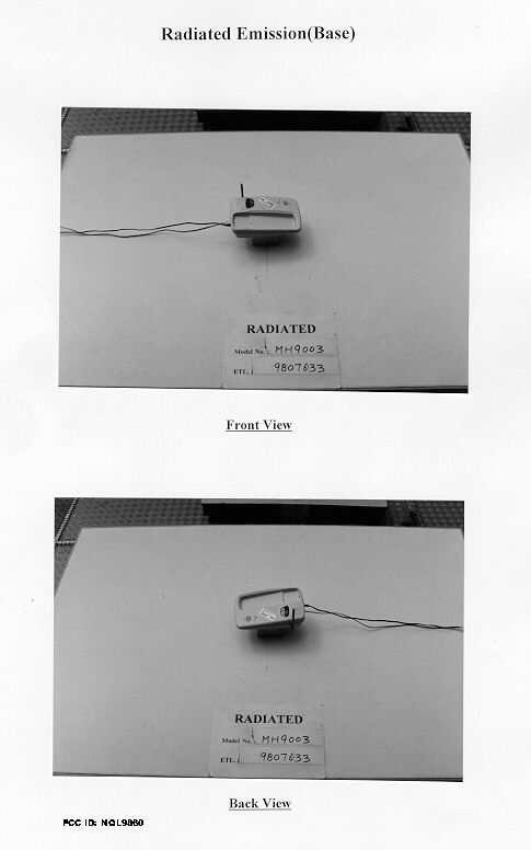
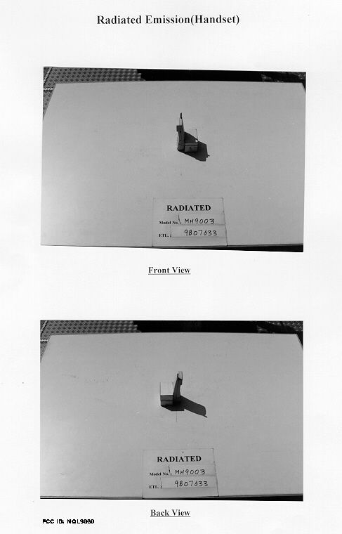
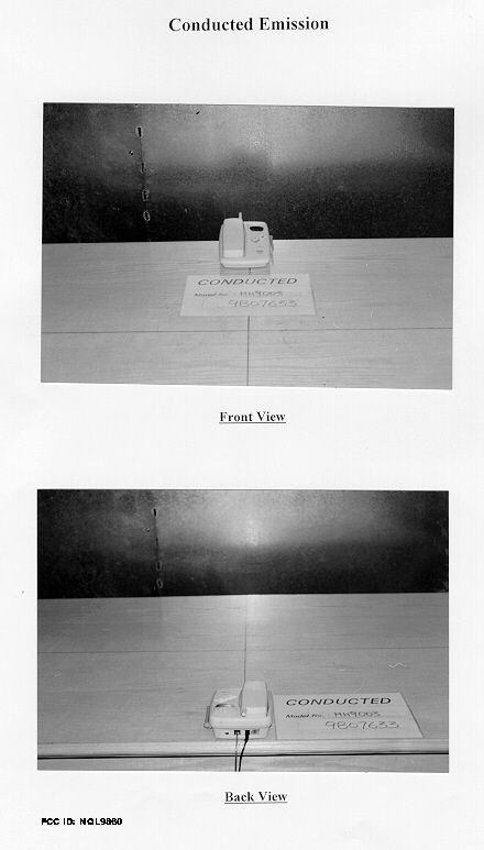
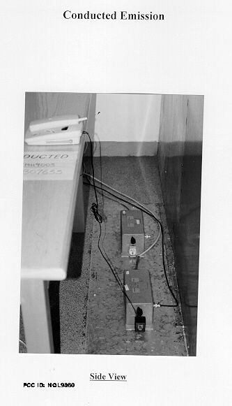
• The test results reported in this report shall refer only to the sample actually tested and shall not refer or be deemed to refer to bulk from which such a sample may be said to have been obtained. • This report shall not be reproduced except in full without prior authorization form Intertek Testing Services Limited FCC ID: NQL9860 Greatsino Limited Application For Certification 900MHz Cordless Telephone (FCC ID: NQL9860) WO# 9807633 CKL/at August 28, 1998 INTERTEK TESTING SERVICES FCC ID: NQL9860 i LIST OF EXHIBITS INTRODUCTION EXHIBIT 1:General Description EXHIBIT 2:System Test Configuration EXHIBIT 3:Emission Results EXHIBIT 4:Equipment Photographs EXHIBIT 5:Product Labelling EXHIBIT 6:Technical Specifications EXHIBIT 7:Instruction Manual EXHIBIT 8:Security Code Information INTERTEK TESTING SERVICES FCC ID: NQL9860 ii MEASUREMENT/TECHNICAL REPORT Greatsino Limited - MODEL: MH9003 FCC ID: NQL9860 This report concerns (check one:)Original Grant X Class II Change Equipment Type: Low Power Transmitter (example: computer, modem, transmitter, etc.) Deferred grant requested per 47 CFR 0.457(d)(1)(ii)?Yes No X If yes, defer until : date Company Name agrees to notify the Commission by: date of the intended date of announcement of the product so that the grant can be issued on that date. Transition Rules Request per 15.37?Yes No X If no, assumed Part 15, Subpart C for intentional radiator - the new 47 CFR [10-1-96 Edition] provision. Report prepared by:C. K. Lam Intertek Testing Services. 2/F., Garment Centre, 576 Castle Peak Road, Kowloon, Hong Kong. Phone:852-2746-8218 Fax:852-2785-5487 INTERTEK TESTING SERVICES FCC ID: NQL9860 iii Table of Contents 1.0 General Description ................................................................................................................. 2 1.1 Product Description ................................................................................................................ 2 1.2 Related Submittal(s) Grants .................................................................................................... 3 1.3 Test Methodology ................................................................................................................... 3 1.4 Test Facility ............................................................................................................................ 3 2.0 System Test Configuration ...................................................................................................... 5 2.1 Justification............................................................................................................................. 5 2.2 EUT Exercising Software ....................................................................................................... 5 2.3 Support Equipment List and Description ................................................................................ 6 2.4 Equipment Modification ......................................................................................................... 7 3.0 Emission Results ....................................................................................................................... 9 3.1 Field Strength Calculation..................................................................................................... 10 3.2 Radiated Emission Configuration Photograph - Base Unit.................................................... 11 3.3 Radiated Emission Data - Base Unit..........................................................................................12 3.4 Radiated Emission Configuration Photograph - Handset .........................................................18 3.5 Radiated Emission Configuration Data - Handset ................................................................. 19 3.6 Radiated Emission on the bandedge...................................................................................... 23 3.7 Line Conducted Configuration Photograph - Base Unit ....................................................... 24 3.8 Line Conducted Data - Base Unit ..............................................................................................25 4.0 Equipment Photographs ........................................................................................................ 28 5.0 Product Labelling ................................................................................................................... 30 6.0 Technical Specifications ......................................................................................................... 32 7.0 Instruction Manual ......................................................................................................................34 8.0 Security Code Information .........................................................................................................36 INTERTEK TESTING SERVICES FCC ID: NQL9860 iv List of attached file Exhibit typeFilename Test Reportreport .doc Test Setup Photobase.jpg, handset.jpg conduct1.jpg, conduct2.jpg External Photoophoto1.jpg, ophoto2.jpg Internal Photoiphoto1.jpg to iphoto14.jpg Block Diagramblock.pdf Schematiccircuit.jpg, circuitb.pdf, circuith.pdf ID Labellabel.pdf ID Locationlocation.pdf User Manualmanual.pdf Test Reportbw.pdf Cover Letterletter.pdf Technical Descriptiondescri.pdf Test Reportconduct.pdf INTERTEK TESTING SERVICES FCC ID: NQL9860 1 EXHIBIT 1 GENERAL DESCRIPTION INTERTEK TESTING SERVICES FCC ID: NQL9860 2 1.0 General Description 1.1Product Description The equipment under test (EUT) is a 900 MHz Basic Cordless Phone with model no.: MH9003. The unit is capable of either tone or pulse dialing. The internal power supply's isolation is accomplished through a power transformer having an adequate dielectric rating. The circuit wiring is consistent under the requirement of part 68. The handset unit consists of a keypad with twelve standard keys (0,...9,*,#), five function keys (flash, redial, memo, tone, pause), and on…
Text truncated - open the document above for the full version.
Contact Information
Applicant
C Chan(Marketing Manager)
9-011-852-2736-8868Fax: 9-011-852-2730-5176
Technical Contact
INTERTEK TESTING SERVICES HONG KONG LTD.C.K. LAM
[email protected](852)2746-8211
2/F., GARMENT CENTRE, · KOWLOON · Hong Kong
Non-Technical Contact
INTERTEK TESTING SERVICES HONG KONG LTD.C.K. LAM
[email protected](852)2746-8211
Test Firm
Intertek Testing Services Hong KongBilly Chow
Technical Specifications
| # | Rule Parts | Frequency Range | Power Output |
|---|---|---|---|
| 2 | 15C | 926.125 MHz - 927.1 MHz | - |
Other Applications from Greatsino Electronic Limited
NQL9960
Jun 27, 1999DXT - Part 15 Low Power Transceiver, Rx Verified
Equipment Class
DXT - Part 15 Low Power Transceiver, Rx Verified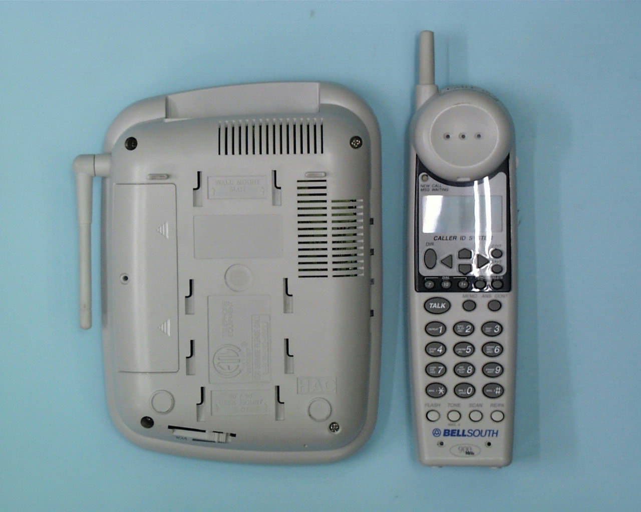
NQL9950
Apr 29, 1999900 MHz Cordless Telephone
Equipment Class
DXT - Part 15 Low Power Transceiver, Rx Verified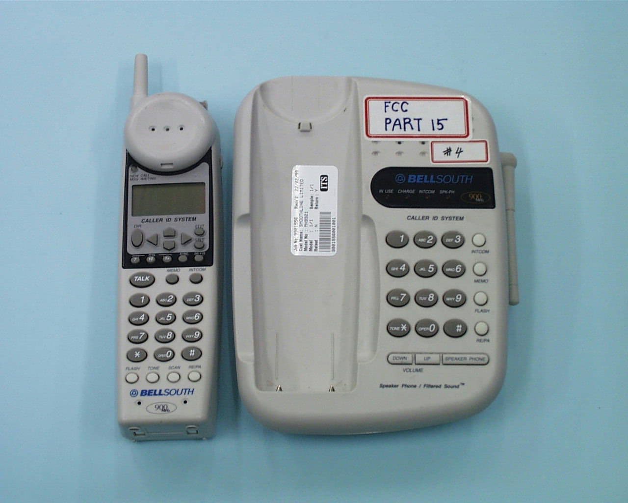
NQL9940
Apr 18, 1999DXT - Part 15 Low Power Transceiver, Rx Verified
Equipment Class
DXT - Part 15 Low Power Transceiver, Rx Verified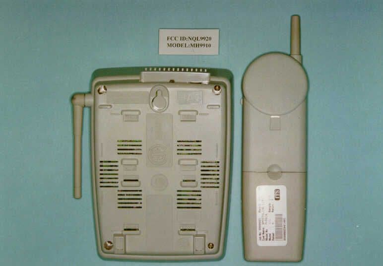
NQL9920
Mar 30, 1999DXT - Part 15 Low Power Transceiver, Rx Verified
Equipment Class
DXT - Part 15 Low Power Transceiver, Rx Verified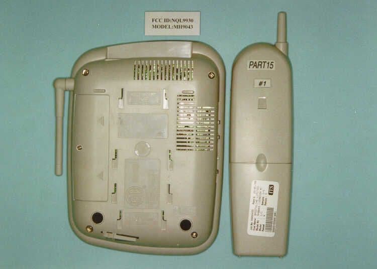
NQL9930
Mar 28, 1999DXT - Part 15 Low Power Transceiver, Rx Verified
Equipment Class
DXT - Part 15 Low Power Transceiver, Rx Verified