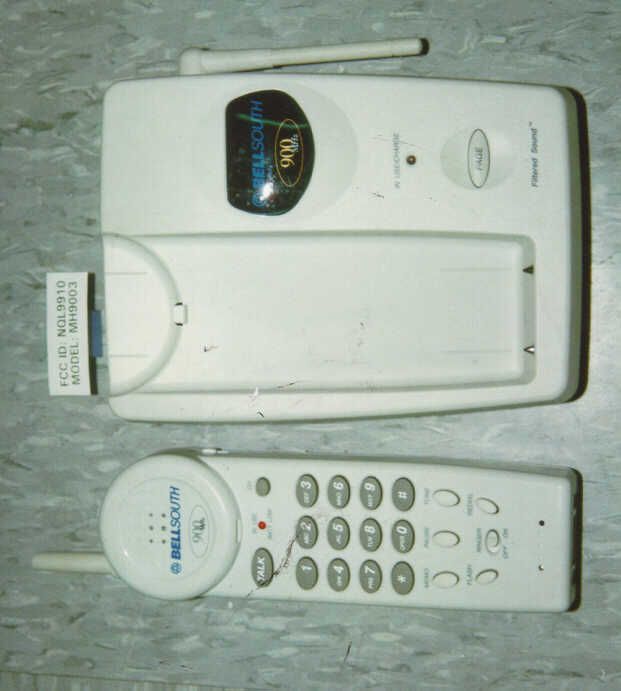
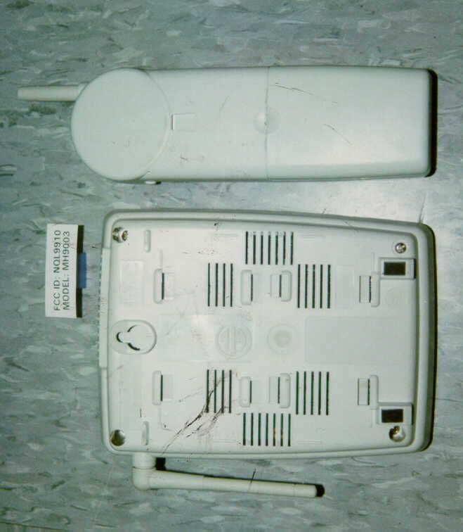
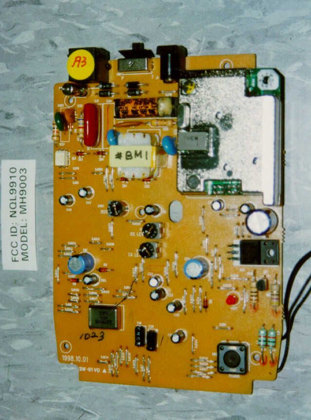
NQL9910900MHz Analog Modulation 40 Channels Cordless Phon
Greatsino Electronic Limited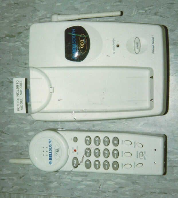
Click to zoom
Application Details
- Equipment Class
- DXT - Part 15 Low Power Transceiver, Rx Verified
- Date of Grant
- Feb 25, 1999
- Application Purpose
- Original Equipment
- Date of Application
- Dec 22, 1998
- Equipment Note
- 900MHz Analog Modulation 40 Channels Cordless Phon
- Frequency Range
- 926.12500000 - 927.10000000
- Company
- Greatsino Electronic Limited
- Country
- Hong Kong
Documents & Files
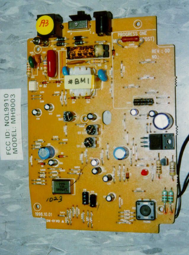
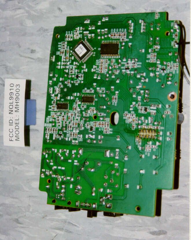
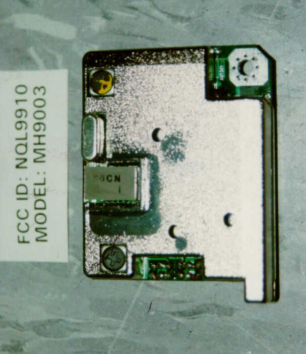
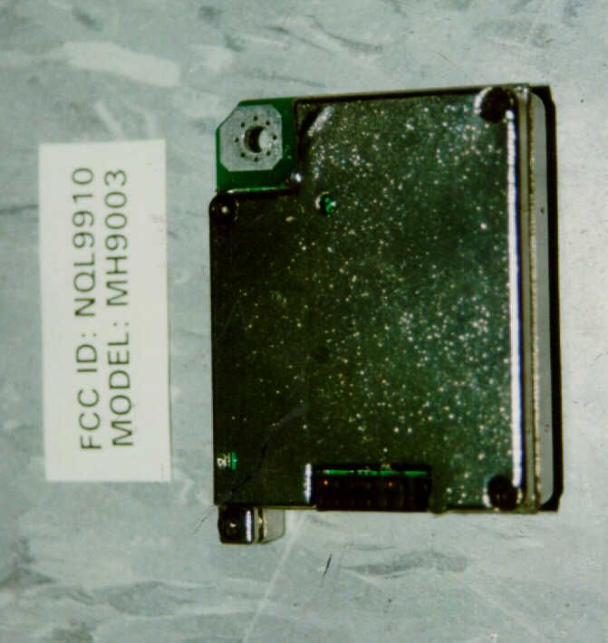
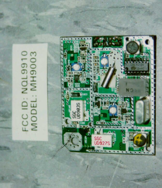
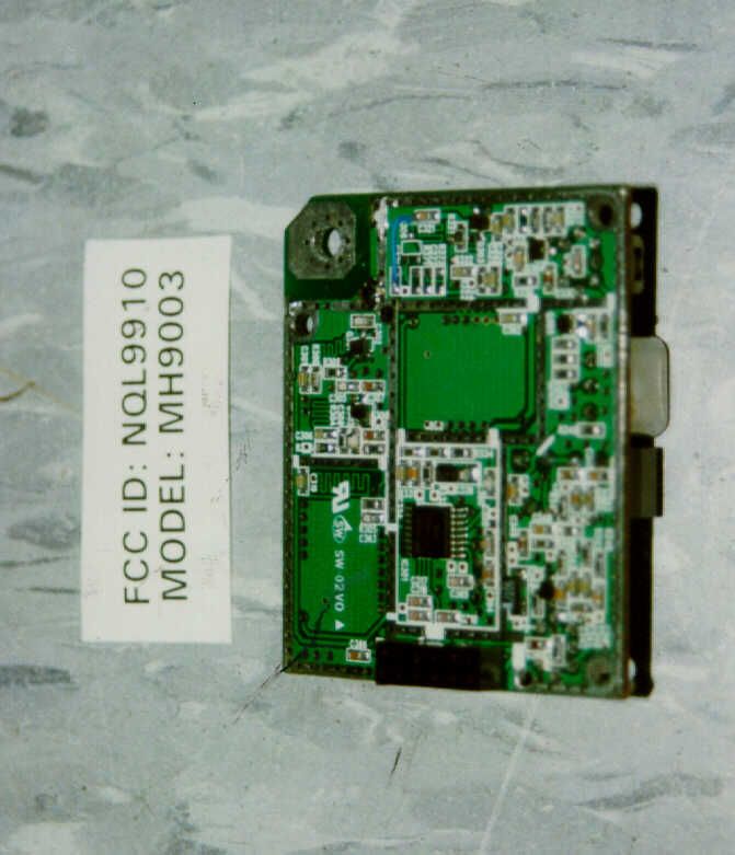
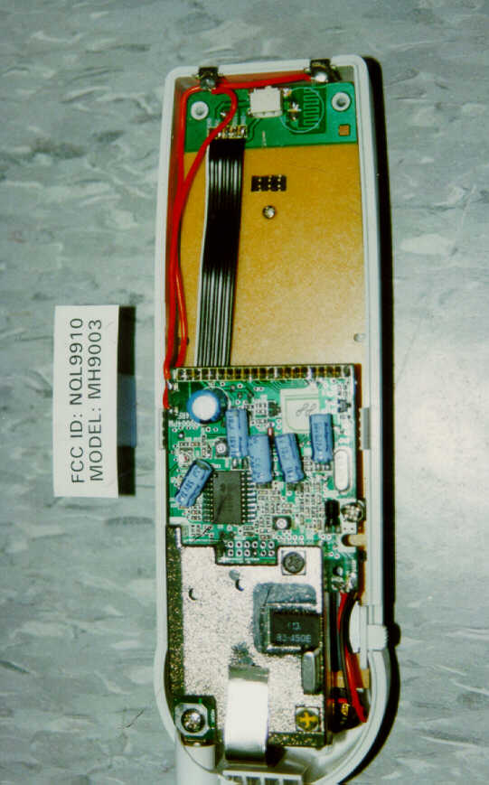
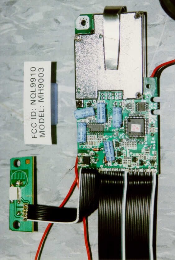
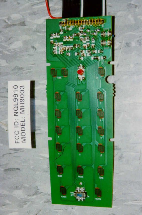
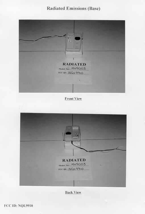
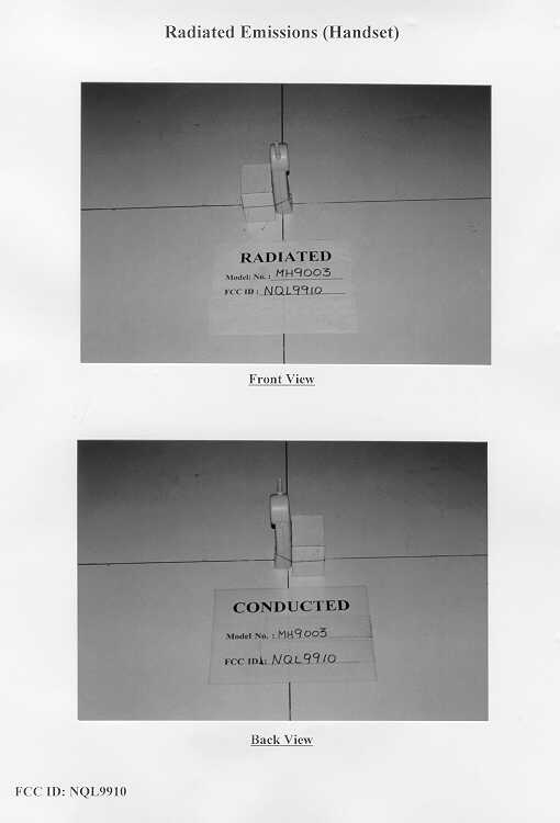
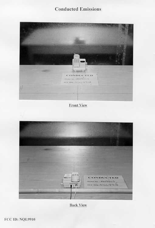
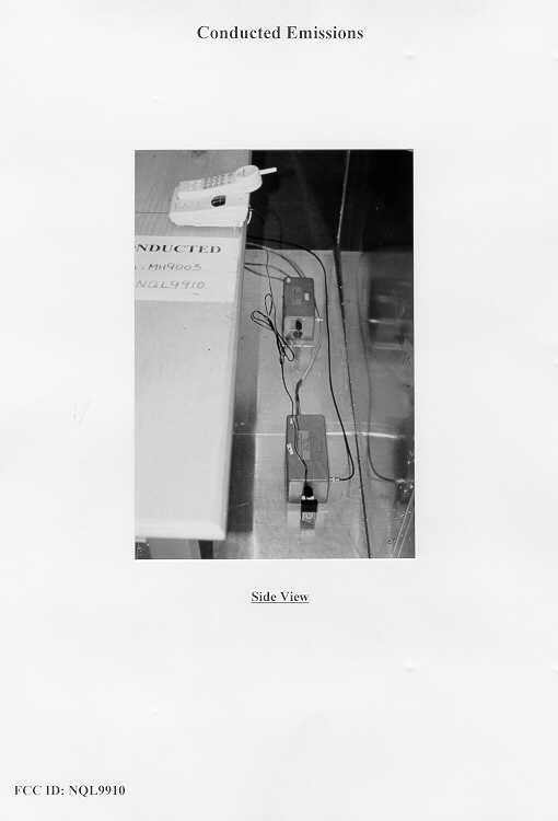
Document Text
Text extracted from the exhibit documents filed with the FCC. Open a document above to read the original.
Users Manual
1 Safety Instructions ................................................................................................. 2 HANDSET Controls - Location and Function ........................................................ 4 BASE UNIT Controls - Location and Function ...................................................... 6 Getting Started ...................................................................................................... 8 Desk Mounting ....................................................................................................... 11 Wall Mounting ........................................................................................................ 12 Basic Operation ..................................................................................................... 13 Receiving Calls ...................................................................................................... 14 Placing Calls .......................................................................................................... 15 HANDSET Redial Feature ...................................................................................... 15 Storing Numbers .................................................................................................... 16 Recalling Stored Numbers .................................................................................... 17 Security .................................................................................................................. 18 Recharging the Battery Pack ................................................................................ 19 Changing the Battery Pack ................................................................................... 20 Problem Solving .................................................................................................... 21 Technical Information ............................................................................................ 23 FCC Requirements ................................................................................................ 24 Warranty Information ............................................................................................. 26 Wall Mount Template ............................................................................................ 32 Contents 2 IMPORTANT SAFETY INSTRUCTIONS To reduce the risk of fire, electric shock and/or injury, always follow these basic safety precautions when using your cordless telephone equipment. 1.Read and understand all instructions. 2.Follow all warnings and instructions marked on the telephone. 3.Unplug this telephone from the wall outlet before cleaning or replacing batteries. Do not use liquid cleaners or aerosol cleaners. Use a damp cloth for cleaning. If necessary, use only a mild soap. 4.Do not use this telephone near a bathtub, kitchen sink, wash bowl, laundry tub, swimming pool, in a wet basement, or anywhere else where there is water. 5.Do not place this telephone on an unstable cart, stand or table. A fall could cause serious damage to the phone. 6. This product should never be placed near or over a radiator or heat register. This product should not be placed in a built-in installation unless proper ventilation is provided. 7.Operate this telephone only with the correct electrical voltage shown on the marking label or in the Owner's Manual. If you are not sure of the voltage in your home, consult your dealer or local power company. 8.Do not allow anything to rest on the power cord. Do not install the phone where people will walk on the cord. 9.Do not overload wall outlets and extension cords. This can increase the risk of fire or electric shock. 10.Never push objects of any kind through slots in the phone. They could touch dangerous voltage points or short out parts that could result in a risk of fire or electric shock. Never spill liquid of any kind on the telephone. 11.To reduce the risk of electric shock, do not take this telephone apart. When service or repair work is required on this telephone, take it to a qualified service representative. Opening or removing covers may expose you to dangerous voltage or other risks. Incorrect re-assembly can cause electric shock when the appliance is used. 12.Unplug this telephone from the wall outlet and consult a qualified service representative in any of the following situations: A. When the power supply cord is frayed or damaged. B. If liquid has been spilled into the telephone. C. If the product has been exposed to rain or water. D. If the telephone does not operate normally by following the operating instructions. Adjust only those controls that are covered by the operating instructions. Improper adjustment of other controls may result in damage and will often require extensive work by a qualified technician to restore the telephone to normal operation. E. If the telephone has been dropped or the case has been damaged. Safety Instructions 3 Safety Instructions F. If the telephone exhibits a distinct change in performance. 13.Avoid using a telephone (other than a cordless type) during an electrical storm. There may be a remote risk of electric shock from lightning. 14.Do not use the telephone to report a gas leak in the vicinity of the leak. 15.Never install telephone wiring during a lightning storm. 16.Never install telephone jacks in wet locations unless the jack is specifically designed for wet locations. 17.Never touch uninsulated telephone wires or terminals unless the telephone line has been disconnected at the network interface. 18.Use caution when installing or modifying telephone lines. Battery Safety CAUTION: To reduce the risk of fire or personal injury, read and follow these instructions: 1.Use only the following type and size battery pack: Cordless Telephone Battery Pack 3.6V, 600mAh U.S. Electronics Inc. Ni-Cd Battery Pack: model B650 (See page 19 for ordering information.) 2.Do not dispose of the battery pack in a fire. It may…
Text truncated - open the document above for the full version.
Block Diagram
Base Main Block Diagram BASE MAIN BLOCK DIAGRAM A MH-9003 A3 11 T ue sda y, D ece m ber 0 1, 199 8 TitleSize Document Number Rev Date: Sheet of VCC VCC UNREG VCC UNREG VCC VCC UNREG Q2 TXCONTROL CHARGEDETECT CHARGE CONTROL CHARGECONTACT 3.579545MHz RELAY CONTROL IC6 7805 POWERJACK 350mA IN OUT 1000uF/16V TX TIP RING BASE CPU uPD789024 RX EXPANDER COMPRESSOR IC4A DTMF OUT RING INPUT EXP IC4A IC5B IC5A IC5D 1319 EXP EXP OUT IC1 Q3 LED FUNCTION FILTER Amp COM. Fin C.OUT 2 3 1 118 COM.MUTE CON.IN DATA DATA RESET, POWER MAIN BLOCK DIAGRAM 15 EXP IN MUTE F.OUT IC3 DC9V VSS 16,39 X-OUT X-IN 1415 4344 1 23 6 - 11 363534 33 41 26 2 27 5,7 42 1830323140 CKT, Q6 Q5 INUSE Q4 SIDETONE CKT SMOOTHLINE LTD. 17,38 T1 LS1 D1 - D4 X-TAL 220 uF / 16V Q1 LEDATACLK TX B + BUSY AF O UT AF IN Handset Main Block Diagram PORTABLE M AIN BLOCK DIAGRAM A MH-9003 A3 11 Tuesday, December 01, 1998 TitleSize Document N umber Rev Date: Sheet of VCC B+ B+ RX B+ Q6 RESET CKT 3.579545MHz POWER CONTROL CKT PORTABLE MAIN BLOCK DIAGRAM CPU uPD789024 RX EXPANDER COMPRESSOR EXP IC4D IC4C IC4B 13 19 E. MUTE EXP OUT FILTER Amp COM. Fin c.out 2 3 1 11 8 com.mut com.in DATA Q7,Q8 LOWDETECT CKT BATT TX RINGER S/W Q10 Q2 BUZZER CONTROL CKT Vss 16,39 3 1 85 AUDIO AMP RECEIVER IC4B MIC TX DATA CKT RX POWER CONTROL CKT DIAL KEY MATRIX 1 - 3 7 - 11,44 CUT OFF CKT Q3 16 EXP IN CHARGE CONTACT BATT 1.2Vx3 CHARGE DETECT CKT ON/OFF 43 17,38 18 2642 19 303231 29 41 23 4 27 6 1415 2221 5 X-INX-OUT BUZZER SMOOTHLINE LTD. X-TAL LEDATA CLK BUSY AF O UT AF IN TX B + RX B+ Base RF Block Diagram BASE RF BLOCK DIAGRAM A MH-9003 A3 11 Saturday, Novem ber 07, 1998 TitleSize D ocument Num ber Rev D ate : S hee t of RB+ 9 1 3 VCO IN AMP AMP 902/927MHz LIMITER AMP DEMODULATOR (450KHz) 2nd 11.15MHz REFERENCEX-TAL VC301 MOD IN QUADCOIL IFAMP POWER FRE 5 8 16 AF AMP 4 out B.P.F B.P.F MCF (10.7MHz) V.C.O (LOCAL) MIXER PLL IC FM IF IC BLOCK DIAGRAM 57 12 10 14 16 15 2 3 SMOOTHLINE LTD. MIXER VCC L.N.A FIN1 D01 XOUT XIN FI2 DO2 11 IF FILTER TX B+ RX B+ LMX1602 DBL5018 RF BASE AF OUT BUSY DATACLKLE AF IN TX B+ RX B+ Handset RF Block Diagram PORT RF BLOCK DIAGRA M A MH-9003 A3 11 Saturday, November 07, 1998 TitleSize D ocument Num ber R ev Date: Sheet of RB+ 9 1 3 VCO IN AMP AMP 902/927MHz LIMITER AMP DEMODULATOR (450KHz) 2nd 11.15MHz REFERENCEX-TAL VC301 MOD IN QUADCOIL IFAMP POWER FRE 5 8 16 AF AMP 4 out B.P.F B.P.F MCF (10.7MHz) V.C.O (LOCAL) MIXER PLL IC FM IF IC BLOCK DIAGRAM LMX1602 57 12 10 14 16 15 2 3 SMOOTHLINE LTD. MIXER VCC L.N.A FIN1 D01 XOUT XIN FI2 DO2 11 IF FILTER TX B+ RX B+ DBL5018 RF PORT AF OUT BUSY DATACLKLE A F IN TX B+ RX B+
Operational Description
MODEL NUMBER ALLOCATION Presently, we have a large number of models within each of our various model number series of cordless telephones. Our clients continually request slightly different cosmetic variations of each registered model such as a different case color . In order to control all of these permutations, it is constantly necessary to assign and file, with the FCC, new model numbers to cover these cosmetic variations. Since all models, within a series of cordless telephones, are electrically and functionally identical, varying only in cosmetic detail and to avoid the need to constantly file, with the FCC, to register additional model numbers for cosmetic purposes, we request to register our models as listed tradenames and model numbers: TRADENAMESMODEL NUMBERS BELLSOUTHD(HAC) MH9003(0)(Y)D(HAC) MH9014(0)(Y) AMERITECHD(HAC) MH9004(0)(Y)D(HAC) MH9015(0)(Y) BELL ATLANTICD(HAC) MH9101(0)(Y)D(HAC) MH9016(0)(Y) PACIFIC BELLD(HAC) MH9011(0)(Y)D(HAC) MH9017(0)(Y) UNISONICD(HAC) MH9012(0)(Y)D(HAC) MH9018(0)(Y) D(HAC) MH9013(0)(Y)D(HAC) MH9019(0)(Y) NOTE:(0) Zero=Additional charger base suffix "Y" can be added to the model number to represent color variation, can be any letter/s of the alphabet as follows (but not limited to this list) such as : "No suffix"=Gray case B/BK=Black case HG/VHG=Green case W=White case R=Red case RB=Red/Black case PL=Pearl white case such that : MH9003-Model MH9003 is the standard model in gray case MH9003B-Model MH9003 in black case MH9003HG-Model MH9003 in green case FREQUENCE OF 1602 P.L.L * CHANNEL SPACE: 25KHz * 1st I.F.: 10.7 MHz * 2nd I.F.: 450KHz * TCXO(X-TAL): 11.15MHz BASE(MHz)PORTABLE(MHz) CHTXLOCAL(10.7) TXLOCAL(10.7) 1902.125936.825926.125891.425 2902.150936.850926.150891.450 3902.175936.875926.175891.475 4902.200936.900926.200891.500 5902.225936.925926.225891.525 6902.250936.950926.250891.550 7902.275936.975926.275891.575 8902.300937.000926.300891.600 9902.325937.025926.325891.625 10902.350937.050926.350891.650 11902.375937.075926.375891.675 12902.400937.100926.400891.700 13902.425937.125926.425891.725 14902.450937.150926.450891.750 15902.475937.175926.475891.775 16902.500937.200926.500891.800 17902.525937.225926.525891.825 18902.550937.250926.550891.850 19902.575937.275926.575891.875 20902.600937.300926.600891.900 21902.625937.325926.625891.925 22902.650937.350926.650891.950 23902.675937.375926.675891.975 24902.700937.400926.700892.000 25902.725937.425926.725892.025 26902.750937.450926.750892.050 27902.775937.475926.775892.075 28902.800937.500926.800892.100 29902.825937.525926.825892.125 30902.850937.550926.850892.150 31902.875937.575926.875892.175 32902.900937.600926.900892.200 33902.925937.625926.925892.225 34902.950937.650926.950892.250 35902.975937.675926.975892.275 36903.000937.700927.000892.300 37903.025937.725927.025892.325 38903.050937.750927.050892.350 39903.075937.775927.075892.375 40903.100937.800927.100892.400 MH-9003 (V4) CIRCUIT DESCRIPTION A. BASE UNIT 1. TEL-LINE INTERFACE 2. RING DETECT 3. POWER SUPPLY 4. AUDIO AMPLIFIER AND COMPANDOR 5. DTMF GENERATOR 6. 20dB/30dB CONTROL 7. DATA COMMUNICATION INTERFACE 8. INTERCOM FUNCTION 9. BASE RF MODULE B. PORTABLE UNIT 1. LOW BATTERY DETECTION CIRCUIT 2. BUZZER 3. INDICATOR CATEGORY 4. AUDIO AMPLIFIER AND COMPANDOR 5. PORTABLE RF MODULE A. BASE SET 1. TEL-LINE INTERFACE TEL-LINE INTERFACE CIRCUIT CONSISTS OF A RELAY,DIODE BRIDGE (D1~D4) ,TRANSFOMER (T1),AND SPEECH NETWORK CIRCUIT AS FOLLOWS FIG.1 A DC LOOP IS CONFIGUED WHEN CPU PIN 41 ARE SET HIGH THE LOOP CURRENT FLOWS AS FOLLOWS : TIP1(1)->FUSE1->R35->T1->D2,D1/D3,D4->RING1(1) THE PULSE SIGNAL FROM CPU PIN 41 ARE TRANSMITTED THROUGH LS1 TO TURN ON AND OFF THE TEL LINE. FIG.1 TIP RIN G LS-RELAY1 DIODE D1-D4 PIN 41 OF CPU SP EE CH NETWORK CIRCU IT Q1, LM324 LINE1 T1 TRANSFORMER 2. RING DETECT THE RING SIGNAL SUPPLIED BETWEEN T AND R PASSES THROUGH THE FLLOWING PROCEDURES AND IS DETECTED BY THE CPU. FIG.2 3. POWER SUPPLY 3-1 THE OUTPUT VOLTAGE OF IC6 IS REGULATED 5V AND THIS VOLTAGE IS USED BY MAIN SUPPLYIING VOLTAGE OF CPU AND TX,RX POWER. FIG.3 RIN G TIP C31, R34 PC817CP U P IN 23 ADAPTOR 9V, 350mA RE G UL ATOR IC6 UNREG VC C (5 V) 4. AUDIO AMPLIFIER AND COMPANDOR 4-1 TX PART: THE TRANSMITTED SIGNALS FROM TELEPHONE LINE ARE FEED TO COMPANDOR IC(IC2) THROUGH THE AUDIO AMPLIFIER AND THE RECEIVED SIGNALS FROM TELEPHONE LINE ARE ALSO FEED TO AUDIO AMPLIFIER THROUGH THE SPEECH NETWORK CIRCUIT. FIG.4 4-2 RX PART: THE RECEIVED SIGNALS FROM AF OUT OF RF MODULE, FEED TO COMPANDOR FOR NOISE ELIMINATION. THIS SIGNAL THROUGH MATCHING TRANS T1,ALSO FEED TO TELEPHONE LINE THROUGH THE SPEECH NETWORK CIRCUIT TO TRANSFER TO OTHER PARTY. FIG.5 TEL-LINETRANS T1 SP EE CH N ETW O RK CIRCU IT COMPANDOR IC IC2 R F , A F IN MUTE, CPU P IN 1 TEL-LINETRANS T1 SPEECH NETWORK CIRCU IT COMPANDOR IC IC2 R F , A F O U T MUTE, CPU P IN 2 5. DTMF GENARATOR THE CPU DTMF GENARATOR IS INTENDED TO PROVIDE DUAL-TONE MULTI-FREQUENCY (DTMF) FOR TONE DIALLING SYSTEM. THE DTMF SIGNAL THROUGH SPEECH NETWORK CIRCUIT OUTPUT TEL-LINE. DTMF CONTROL PIN 6,7,8,9,10,11 OF CPU FIG.6 6. 20dB CONTROL RSSI LEVEL (20 dB) OUTPUT FROM THE IF CIRCUIT THROUGH IC5D OPAMP OUT OF IS DETECTING BY PIN 42 OF CPU. FIG.7 CPU PIN 6-11CIRCUIT SPEECH NETWORKDTMF GENERATORTEL LINE IC5D, OP AMPIF CIRCU IT 20dB PIN 42 OF CPU 7. DATA COMMUNICATION INTERFACE. * DATA COMMUNICATION IS OPERATED SERIAL OUTPUT 7-1 PIN 26 (SI) OF CPU : DATA SIGNAL WILL RECEIVE FROM THE PORTABLE UNIT AS THROUGH FILTER CIRCUIT IC5A, IC5B AND DATA SIGNAL INPUT PIN 26 (SI) OF CPU 7-2 PIN 27 (SO) OF CPU : DATA SIGNAL WILL SEND TO THE PORTABLE UNIT AS THROUGH PIN 27 (SO) OF CPU FIG.8 8. PAGING FUNCTION PAGING FUNCTION CAN BE SELECTED EITHER FROM BABE TO PORTABLE UNIT. THE INTERCOM FUNCTION CAN BE ENABLED BY PRESSING THE PAGING KEY IN THE BASE SET. FIG.9 PIN 27 (SO) OF CPUAF IN IC5 A , IC5 B(SI) PIN 26 OF CPUFILTER CIRCUITAF OUT PAGING KEY RF MODULE AF-IN CP U 9. BASE RF MODULE 9-1. RX PART THE RECEIVER FRONT-END CONTAINS A BAND PASS FILTER, …
Text truncated - open the document above for the full version.
Schematics
Base Main Schematic Diagram Handset Main Schematic Diagram
Schematics
Base RF Schematic Diagram Handset RF Schematic Diagram
Contact Information
Applicant
C Chan(Marketing Manager)
9-011-852-2736-8868Fax: 9-011-852-2730-5176
Technical Contact
Intertek Testing Services Hong Kong Ltd.C.K. Lam
[email protected](852)2746-8211
2/F., Garment Centre, · Kowloon · Hong Kong
Non-Technical Contact
Intertek Testing Services Hong Kong Ltd.C.K. Lam
[email protected](852)2746-8211
Test Firm
Intertek Testing Services Hong KongBilly Chow
Technical Specifications
| # | Rule Parts | Frequency Range | Power Output |
|---|---|---|---|
| 2 | - | 926.125 MHz - 927.1 MHz | - |
Other Applications from Greatsino Electronic Limited
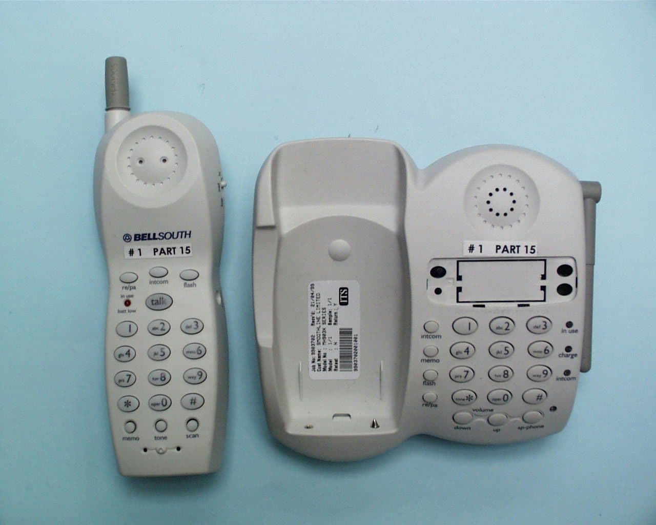
NQL9960
Jun 27, 1999DXT - Part 15 Low Power Transceiver, Rx Verified
Equipment Class
DXT - Part 15 Low Power Transceiver, Rx Verified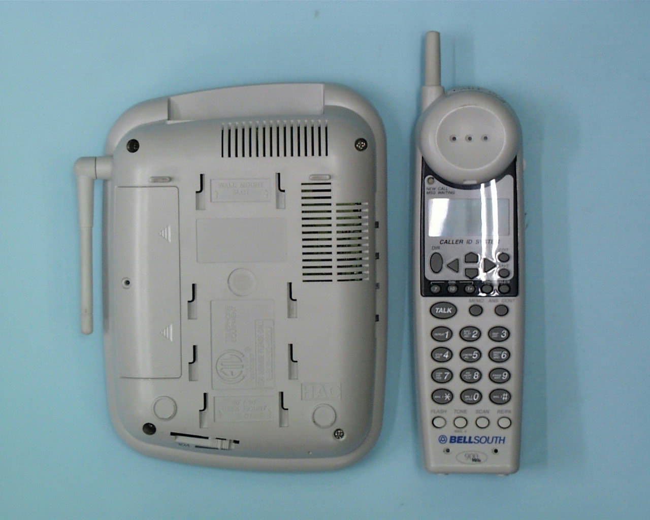
NQL9950
Apr 29, 1999900 MHz Cordless Telephone
Equipment Class
DXT - Part 15 Low Power Transceiver, Rx Verified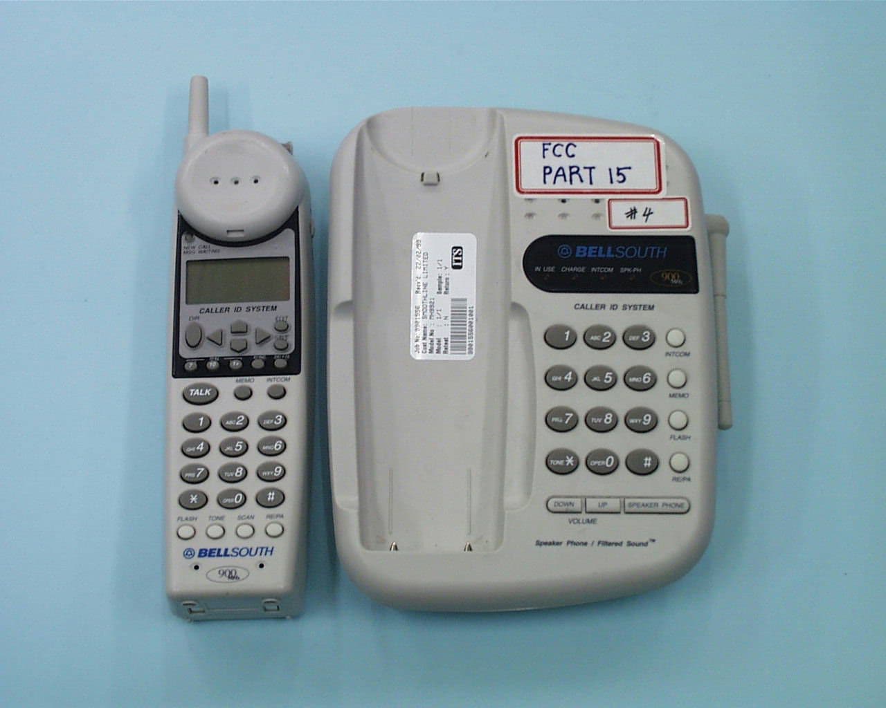
NQL9940
Apr 18, 1999DXT - Part 15 Low Power Transceiver, Rx Verified
Equipment Class
DXT - Part 15 Low Power Transceiver, Rx Verified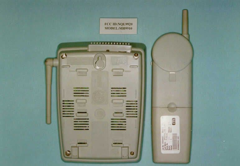
NQL9920
Mar 30, 1999DXT - Part 15 Low Power Transceiver, Rx Verified
Equipment Class
DXT - Part 15 Low Power Transceiver, Rx Verified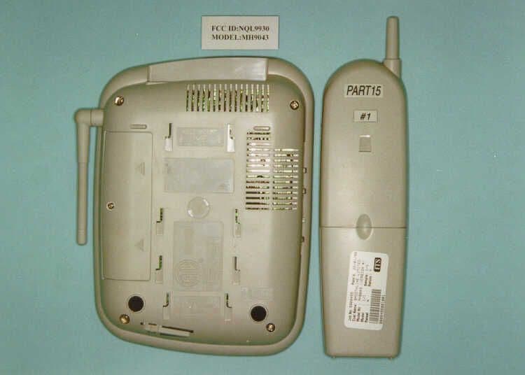
NQL9930
Mar 28, 1999DXT - Part 15 Low Power Transceiver, Rx Verified
Equipment Class
DXT - Part 15 Low Power Transceiver, Rx Verified