NR7A710Multipurpose Laser
AGL Corporation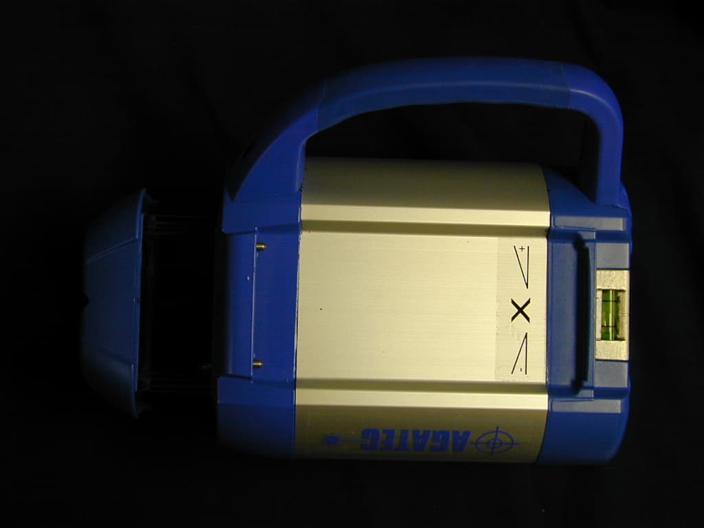
Click to zoom
Application Details
- Equipment Class
- DXT - Part 15 Low Power Transceiver, Rx Verified
- Date of Grant
- Oct 12, 2004
- Application Purpose
- Original Equipment
- Date of Application
- Oct 12, 2004
- Equipment Note
- Multipurpose Laser
- Frequency Range
- 915.40000000 - 915.40000000
- Company
- AGL Corporation
- Country
- United States
Documents & Files
Document Text
Text extracted from the exhibit documents filed with the FCC. Open a document above to read the original.
Users Manual
A710 Multipurpose Laser Owner’s Manual 2 GENERAL INFORMATION Thank you for buying the Agatec A710 laser! Although the A710 is simple to use, we recommend that you read this manual before operating the laser. Description The A710 is a visible universal laser that can be used for leveling, vertical alignment, squaring, and single and dual slope grade control. It has a digital grade display and is ideal for machine control and other dual grade applications. It’s totally waterproof and has a beam designed for pipelaying. It also has scanning and constant squaring for interior jobs. Other advanced features include: totally automatic self-leveling in both horizontal and vertical modes; electronic calibration by the user; and a detachable keypad that can be used as a remote control. Specifications Recommended use 1,000 ft. (300 m) diameter Accuracy ± 3/16” at 100 ft. Leveling range ± 10% in X and Y axes Grade range -10% to +10% in X,Y & Z axes Rotation speeds 60, 150, 300, 450, 600, 720 rpm Scanning lengths Choice of 3 Laser battery NiMh rechargeable Charging time 15 hours Battery life 40 hours Remote control batteries 2 AAA alkaline Dimensions 5” x 4 ½” x 8 1/2” 12.5 x 11.5 x 21.9 cm Weight 7 ¾ lbs. (3.5 kg) Environmental Laser is waterproof: IP67 Remote control is weather- resistant Laser Diode Visible 635 nm, <5mW CDRH/IEC Classification Class 3R Radio Frequency Interference WARNING: This equipment complies with Part 15 of the FCC rules. Any changes or modifications not expressly approved by the manufacturer could void the user’s authority to operate the equipment. Operation is subject to the following two conditions: (1) this device may not cause harmful interference, and (2) this device must accept any interference received, including interference that may cause undesired operation. This equipment has been tested and found to comply with the limits for a Class B digital device, pursuant to Part 15 of the FCC rules. These limits are designed to provide reasonable protection against harmful interference in a residential installation. This equipment generates, uses, and can radiate radio frequency energy and, if not installed and used in accordance with the instructions, may cause harmful interference to radio communications. However, there is no guarantee that interference will not occur in a particular installation. If this equipment does cause harmful interference to radio or television reception, which can be determined by turning the equipment off and on, the user is encouraged to try to correct the interference by one or more of the following measures: Reorient or relocate the receiving antenna Increase the separation between the equipment and receiver Connect the equipment into an outlet on a circuit different from that to which the receiver is connected Consult the dealer or an experienced radio/TV technician for help Notice for Canada This Class B digital device meets all requirements of Canadian Radio Standards Specification RSS-210. Cet appareil numérique de la Class B respecte toutes les exigences du Règlement sur le matériel brouilleur du Canada. Location of FCC labels FCC label (back of laser) FCC label (back of detachable remote control/keypad) 3 Safety Labels Back of laser: A CDRH label COMPLIES WITH 21CFR 1040.10 AND 1040.11 EXCEPT FOR DEVIATIONS PURSUANT TO LASER NOTICE No. 50, DATED JULY 26, 2001 B Serial no. tag AGL Model P/N 2202 Redmond Rd. P.O. Box 189, Jacksonville, AR 72076 C Explanatory label CLASS 3R LASER PRODUCT WAVE LENGTH 630-680 nm MAX. OUTPUT POWER: 5mW LASER LIGHT; AVOID DIRECT EYE EXPOSURE CONFORMS TO IEC 60825-1; 2001 Front of laser with keypad: D Warning label E Aperture label AVOID EXPOSURE. LASER LIGHT IS EMITTED FROM THIS APERTURE D E A B C 4 5 Laser overview 6655 2 3 8 7 1 5 6 4 9 1 Rotating laser beam (head enclosed in glass lighthouse) 2 Non-rotating laser beam for plumb, squaring, or pipeline 3 Sighting notches for X & Y axes 4 Remote control with digital display 5 Detachable handle 6 Charger jack 7 Bubble vial for vertical setup 8 On/Off 9 Adjustable feet for vertical setup 13 12 1011 14 18 15 10 Multifunction (multi) key Remote control 17 16 11 H.I. Alert keypad 12 Backlight for display 13 On / Off 14 Enter settings for grade 15 X or Y axis (or Z axis) 16 Automatic / manual mode (or left / right adjustment) 17 Scanning 18 Rotation Remote control display 19 20 19 Grade display for X axis 20 Grade display for Y axis (Z axis when in vertical mode) 21 Rotation direction & speed / Scanning 22 H.I. Alert safeguard 22/23 Manual mode (hand symbol) 23 Indicates when level or grade is reached 24 Battery / Charging 25 Out-of-leveling-range indicator 26 Horizontal / Vertical 27 Calibration mode (or Z axis ' left / right adjustment) 28 Communication status between laser & remote control (or backlight indicator) ψ : radio mode ↑ : infrared mode 22232425262728 21 6 7 HOW TO USE THE A710 Setup Horizontal The laser can be used on a 5/8-11 tripod, on a wall mount, or directly on a solid, stable surface. Vertical The laser can be placed directly on a solid, stable surface. If you are using it in a pipe or other confined space, you can detach the handle with a 3mm Allen wrench so it has a narrower profile. Place the laser on the side with the two adjustable feet (9). Rough level the laser by using the feet to center the bubble in the vertical vial (7). Setup range When the keypad is turned on, an “H” for horizontal mode or a “V” for vertical mode will appear on the display (26). The A710 has a wide self-leveling range; however, if the laser is set up out of the leveling range, a triangle with an exclamation point will appear on the display (25). Turning on the laser Turn on the laser with the On / Off key (8). It does a self-test and the beam blinks while the laser is self-leveling. After it’s leveled, the head rotates and keypad symbol (23) stops blinking. Remote control / keypad The keypad can remain attached to the laser, or it can be detached and used as …
Text truncated - open the document above for the full version.
Block Diagram
Mother Board (AGADOP) Memory Mechanical correction Head Motor (AGAMOT) (AGACOD) Communication (AGADPRC) Power (AGADPBA) x-mit I R rcv I R M M M M Grade X Level Y Data On/Off Level Rx/Tx Rx/Tx RF Tx IR Rx IR Prog Rx/Tx Command Prog Prog On/OffButton Led Battery Load Level X Grade Y Power On Led Battery + - Vial (AGADONIV1,2,3,4)
Operational Description
Radio Module for 300-1000 MHz. Band RMCx4-1 ; RMCx9-1 - Page 1 - General Information The Radio Modules RMCx 4-1 and RMCx 9-1 are transceivers designed for very low power and very low voltage wireless applications. The circuit is mainly intended for the ISM (Industrial, Scientific and Medical) and SRD (Short range Device) frequency bands, at 315, 433, 868 and 915 MHz., or any other frequency in the 300- 1000 MHz range. The Module function supporting hardware handshaking and half-duplex communication. The RF Module communicates with a PC or other RS232 devices over an RS232 link. Parameters can be programmed with the RadioComm Windows based PC program, delivered with the RMCx Main Board. The Module reads data from RS232 serial interface, and if reaches 15 bytes, or if for a period of 1mSec do not receive data on Serial Interface, creates a packet and transmits over the RF link. In Receive Mode, the module looks for a valid preamble, a valid SOF (Start Of Frame), reads the packet, extracts the data, check for CRC, and if it's a valid data packet, will send on the serial interface. The received data is 100% controlled and only valid data will be send via RS line. The RF link is a half-duplex link (data cannot be send and received at the same time). The Module is designed to use hardware handshaking. It tells to PC when can receive data and when not. The READY Output of Module (pin 7) can be connected over the RS 232 level converter to the DSUB9 (pin8) CTS, witch controls the data flow. The range of the system depends on the RF frequency, data rate, output power, type of the antenna, and many other environmental conditions. 0101...SOFLNGADDRDATACRC The Address is optional, the Modules can be addressed; only the addressed Module will receive the data. Electrical Specification Supply Voltage3...3.6V Current consumption Receive8/10mA433/868MHz Transmit29mA433/868MHz Sleep mode1 m A TX power10/5/2DBm 433/868/915 MHz Receiver sensibility-107DBm RF 2.4 Kbaud RF impedance50Ohm 2f0<-62DBc Radio Baud Rate0.6...19.2 KBaud Manchester coded FSK or NRZ Serial Baud Rate 4.8...115. 2 kBaud Logic “0” input Voltage0 - 0.9V Iin –1 m A Logic “1” input Voltage2.6 - VDDV Iin – 1 m A Logic “0” Output Voltage0 - 0,4VIout 10 mA Logic “0” Output Voltage 2.8 - VDDVIout 10 mA TX RX SLEEP READY MCLR VCC GND GND GND ANT RMCx4-1 RMCx9-1 - TOP VIEW- Pin Configuration Preamble 4-255 bites Start Of Frame Length of data Address (optional) Data CRC Radio Module for 300-1000 MHz. Band RMCx4-1 ; RMCx9-1 - Page 2 - At the Antenna input of Module, there is a LC filter to reducing the emission of harmonics, so there is no need for other filters. Programmable Parameters: With the help of RMCx MainBoard, some parameters can be programmed: In a Frequency band (eg. 433 MHz) can be set different TX/RX Frequencies, eg. 433,52 ; 433,68 ; 433,92 MHz, etc. -TX Power -20 dBm - +9 dBm (RMCx 4-1) -20 dBm - +5 dBm (RMCx 9-1) Radio Baud Rate: 0,6-19,2 Kbaud. Serial Baud Rate: 4,8-115,2 Kbaud. Wait time on serial line 1.2 ms, .... NTZ or MANCHESTER transmit mode. - Module Address. - Number of preambles, default is 4. Can be read the SW version Number. RMCx Mainboard Buttons and Switches: Switches J7: Battery /External power J5: KEY / UART Mode. Buttons: A-D : BCD Buttons for the KEY function. Reset , Tx , Prog : Can be set the modes of operations. Modes of Operations: KEY: In this mode of operation, pressing the A-D buttons, the Module will transmit the pressed button BCD coded. If another Main Board is turned on and is switched to KEY mode, the transmitted code will appear on the LED display. UART : In this mode, the Modul will transmit data received on Serial RS232 port. If the length of data is more than 15 bites, (or there is no data for a period of 1ms – this period can be programmed - the Module will raise the READY line (the CTS on the RS232 line will be LO) Radio Module for 300-1000 MHz. Band RMCx4-1 ; RMCx9-1 - Page 3 - Setting the modes of operation: Turning on the main board ( or pressing the Reset button) the Module is in Receiving mode. The Power and RX LEDs are lit. Pressing the A-D keys,(KEY Mode) or receiving data on RS line, (UART Mode) the Module packs the data, creates CRC code and transmits on RF link. The Tx Led will be lit for the period of data transmission. Continuous Transmitting Mode: Pressing the Tx and Reset button and depressing the Reset button before the TX button, the Module will enter in Tx Mode. The Module transmits the string ‘Radio test’ on the RF link, With the help of this Mode can be tested the Receive Mode of other Modules, or the range of the system. Programming Mode: Pressing the Prog and Reset button and depressing the Reset button before the Prog button, the Module will enter in Programming Mode. In this mode, with the help of the RadioComm program can be set different parameters of the Module. Ending the program mode, the Module must be reset, otherwise sending data to the Module will reprogram it, or can be damaged. RadioComm program: With the help of RadioComm.exe Win. based program, the RMCx4-1 and RMCx9-1 Modules the main parameters can be read or write. Pressing the Prog and Reset button and depressing the Reset button before the Prog button, the Module will enter in Programming Mode. Radio Module for 300-1000 MHz. Band RMCx4-1 ; RMCx9-1 - Page 4 - Program menus: File =>Exit Settings =>Serial port: can be set the serial port and the Baud Rate of the PC. The default Baud Rate of the Module is 38.4.KBaud. • TX Power: Can be set the output power from –20 dBm to +10 dBm (433MHz) or +5 dBm (900 MHz) • TX Frequency: Can be set the Rx/Tx frequency. Here is the list of the frequencies can be set for the two kind of Modules (MHz): RMCx-4 433.2324000, 433.3706400, 433.5286286, 433.6164000, 433.9236000, 434.2308000, 434.3185714, 434.4765600, 434.6148000 RMCx-9 868.5501600, 868.6116000, 868.6884000, 868.7871429, 868.9188000, 869.1031200, 869.2260000, 869.3796000, 869.5770857, 869.6560800, 869.8404000, 902.280…
Text truncated - open the document above for the full version.
Test Report
Master: NemkoPT15249A Date: April 19, 1999 Nemko Test Report: 4L0100RUS1REV3 Applicant: AGL Corporation 2202 Redmond Rd. Jacksonville, AR 72076 Equipment Under Test: A710 Laser w/Wireless Remote Control (E.U.T.) In Accordance With: FCC Part 15, Subpart C, 15.249 For 900 MHz Transmitters Tested By: Nemko Dallas Inc. 802 N. Kealy Lewisville, Texas 75057-3136 Authorized By: Dustin Oaks, Account Manager Date: 10/8/2004 Total Number of Pages: 23 Nemko Dallas FCC PART 15, SUBPART C FOR 900 MHz Transmitters Test Report No.: 4L0100RUS1 EQUIPMENT: A710 Page 2 of 23 Table Of Contents Section 1. Summary Of Test Results ........................................................... 3 Section 2. General Equipment Specification................................................ 4 Section 3. Powerline Conducted Emissions................................................. 6 Section 4. Radiated Emissions .................................................................... 9 Section 5. Test Equipment List ..................................................................... 20 ANNEX A TEST DIAGRAMS ........................................................................... 21 Nemko Dallas FCC PART 15, SUBPART C FOR 900 MHz Transmitters Test Report No.: 4L0100RUS1 EQUIPMENT: A710 Page 3 of 23 Section 1. Summary Of Test Results Manufacturer: AGL Corporation Model No.: A710 Serial No.: None General: All measurements are traceable to national standards. These tests were conducted on a sample of the equipment for the purpose of demonstrating compliance with FCC Part 15.249. All tests were conducted using measurement procedure ANSI C63.4-2001. Radiated Emissions were made on an open area test site. New Submission Production Unit Class II Permissive Change Pre-Production Unit THIS TEST REPORT RELATES ONLY TO THE ITEM(S) TESTED. THE FOLLOWING DEVIATIONS FROM, ADDITIONS TO, OR EXCLUSIONS FROM THE TEST SPECIFICATIONS HAVE BEEN MADE. NONE NVLAP LAB CODE: 100426-0 Nemko Dallas Inc. authorizes the above named company to reproduce this report provided it is reproduced in its entirety and for use by the company’s employees only. Any use which a third party makes of this report, or any reliance on or decisions to be made based on it, are the responsibility of such third parties. Nemko Dallas Inc. accepts no responsibility for damages, if any, suffered by any third party as a result of decisions made or actions based on this report. This report applies only to the items tested. Summary Of Test Data NAME OF TEST PARA. NO. RESULT Conducted Emissions 15.207 Complies Radiated Emissions 15.249 Complies Nemko Dallas FCC PART 15, SUBPART C FOR 900 MHz Transmitters Test Report No.: 4L0100RUS1 EQUIPMENT: A710 Page 4 of 23 Canadian/FCC Matrix FCC Section Canada Section 15.249(a) Fundamental RSS210 6.2.2(m2)(1) Fundamental 15.249(a) Harmonics RSS210 6.2.2(m2)(1) Harmonics 15.249(b) RSS210 6.2.2(m2)(3) 15.207 RSS 210 9.0 Section 2. General Equipment Specification Frequency Range: Single Channel Operating Frequency(ies) of Sample: 915.4 MHz Tunable Bands: N/A Number of Channels: 1 Channel Spacing: NA User Frequency Adjustment: None Integral Antenna Yes No Nemko Dallas FCC PART 15, SUBPART C FOR 900 MHz Transmitters Test Report No.: 4L0100RUS1 EQUIPMENT: A710 Page 5 of 23 Description of EUT A visible universal laser that can be used for leveling , vertical alignment, squaring, and single single and dule grade applications. System Diagram Nemko Dallas FCC PART 15, SUBPART C FOR 900 MHz Transmitters Test Report No.: 4L0100RUS1 EQUIPMENT: A710 Page 6 of 23 Section 3. Powerline Conducted Emissions NAME OF TEST: Powerline Conducted Emissions PARA. NO.: 15.207 TESTED BY: Art Ruvalcaba DATE: 3/16/04 Minimum Standard: Limits for conducted disturbance at the mains ports Frequency Range (MHz) Quasi-peak Limits (dBuV) Average Limits (dBuV) 0.15 to 0.50 66-56 56-46 0.50 to 5.00 56 46 5.00-30.0 60 50 The limit decreases with the logarithm of the frequency in the range 0.15MHz to 0.5 MHz Test Results: Complies. Measurement Data: See attached data. Method of Measurement: (Procedure ANSI C63.4-1992) Measurements were made using a spectrum analyzer with 10 kHz RBW, Peak Detector. Any emissions that are close to the limit are measured using a test receiver with 10 kHz bandwidth, CISPR Quasi-Peak Detector. Nemko Dallas FCC PART 15, SUBPART C FOR 900 MHz Transmitters Test Report No.: 4L0100RUS1 EQUIPMENT: A710 Page 7 of 23 Conducted Emissions Powerline Voltage Measurement CompleteXJob # : 4L0100ETest # : CEPV-01 PreliminaryPage1of1 Client Name :AGL Corporation EUT Name :A 710 EUT Model # :A 710 EUT Part # :NONE EUT Serial # :NONE EUT Config. :Rotating Power on Specification :CFR 47 Part 15, Subpart B Class B Reference : 15.207 Transducer # :1258Temp. (deg. C) :12Date : 03/16/04 HP Filter # :1433Humidity (%) :57Time : 10:00 Cable 1 # :1998EUT Voltage :120VACStaff : Art Ruvalcaba Cable 2 # :1194EUT Frequency : 60HzLocation : Lab 3 Detector 1 # :785Peak Bandwidth: 10kHzPhoto ID: 4L0100E CEPV-01 Detector 2 # :NAQP Bandwidth10kHz Limiter # :NAAvg. Bandwidth10kHz Meas.EUTDetectorLimitMeterPathTransducerCorrectedSpec.limitCR/SLPass Freq. TestTypeTypeReadingLossFactorReading(dBuV)Diff.Fail (MHz)Point(P,QP, A)(QP, A)(dBuV)(dB)(dB)(dBuV)Q.P.Avg.(dB)Unc.Comment 0.2NQPQP50.00050.063.61 53.611 -13.6Pass 0.2NAA25.00025.063.61 53.611 -28.6Pass 0.298NQPQP46.00046.060.3 50.299 -14.3Pass 0.298NAA26.00026.060.3 50.299 -24.3Pass 0.396NQPQP37.00037.057.94 47.937 -20.9Pass 0.396NAA15.00015.057.94 47.937 -32.9Pass 1.5NPA32.90032.95646-13.1Pass 0.2HQPQP50.00050.063.61 53.611 -13.6Pass 0.2HAA10.00010.063.61 53.611 -43.6Pass 0.298HQPQP45.00045.060.3 50.299 -15.3Pass 0.298HAA9.0009.060.3 50.299 -41.3Pass 0.396HQPQP41.00041.057.94 47.937 -16.9Pass 0.396HAA6.0006.057.94 47.937 -41.9Pass 0.927HPA35.50035.55646-10.5Pass 1.2HPA30.10030.15646-15.9Pass 1.47HPA35.80035.85646-10.3Pass 2.04HPA28.60028.65646-17.4Pass Scanned .150-30 MHz ..\EMCShare\AUTOMATE\DATASHTS\CEP_Voltage Rev C.xl sDocument Con…
Text truncated - open the document above for the full version.
Contact Information
Applicant
Mr. Larry Zaitz
Test Firm
Nemko Dallas, Inc.Michael Cantwell
Technical Specifications
| # | Rule Parts | Frequency Range | Power Output |
|---|---|---|---|
| 1 | 15C | 915.4 MHz - 915.4 MHz | - |
Other Applications from AGL Corporation
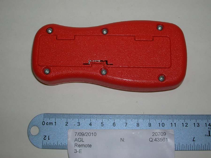
NR7GP15R
Sep 12, 2010Remote Control for Laser Levelling System
Equipment Class
DXT - Part 15 Low Power Transceiver, Rx Verified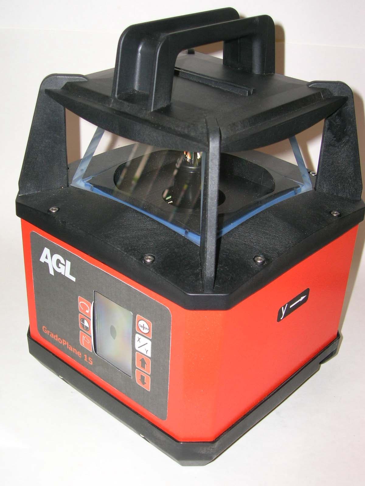
NR7GP15
Sep 12, 2010Laser Levelling System with Remote
Equipment Class
DXT - Part 15 Low Power Transceiver, Rx Verified
NR7MR360R
Nov 22, 2005MR360R Receiver
Equipment Class
DSC - Part 15 Security/Remote Control Transmitter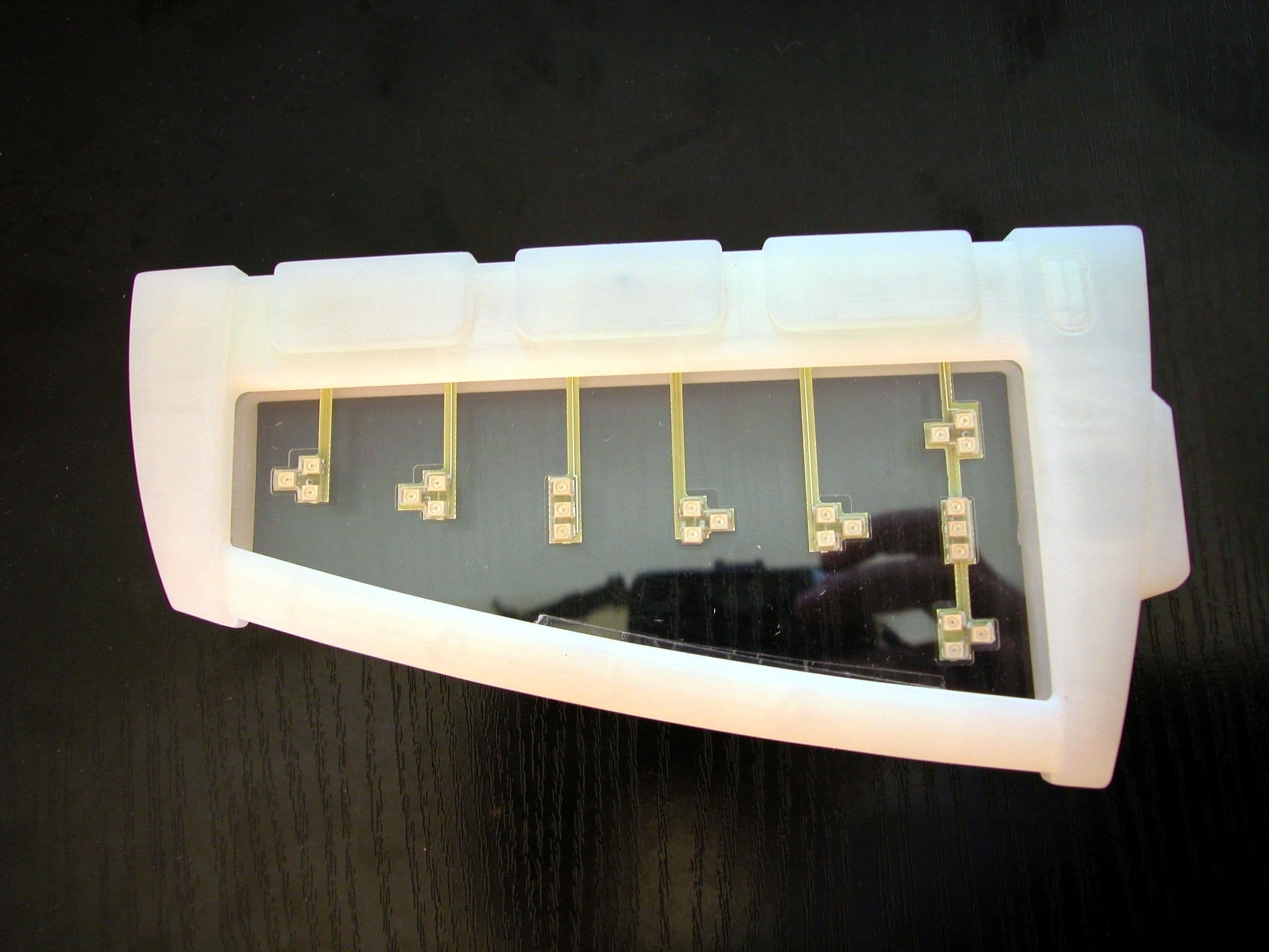
NR7MD360R
Oct 24, 2005MD360R Cabin
Equipment Class
DTS - Digital Transmission System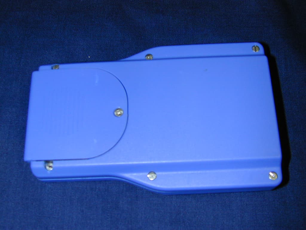
NR7A710HR
Oct 12, 2004Remote Control
Equipment Class
DXT - Part 15 Low Power Transceiver, Rx Verified