NR7MR360RMR360R Receiver
AGL Corporation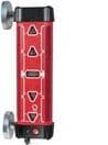
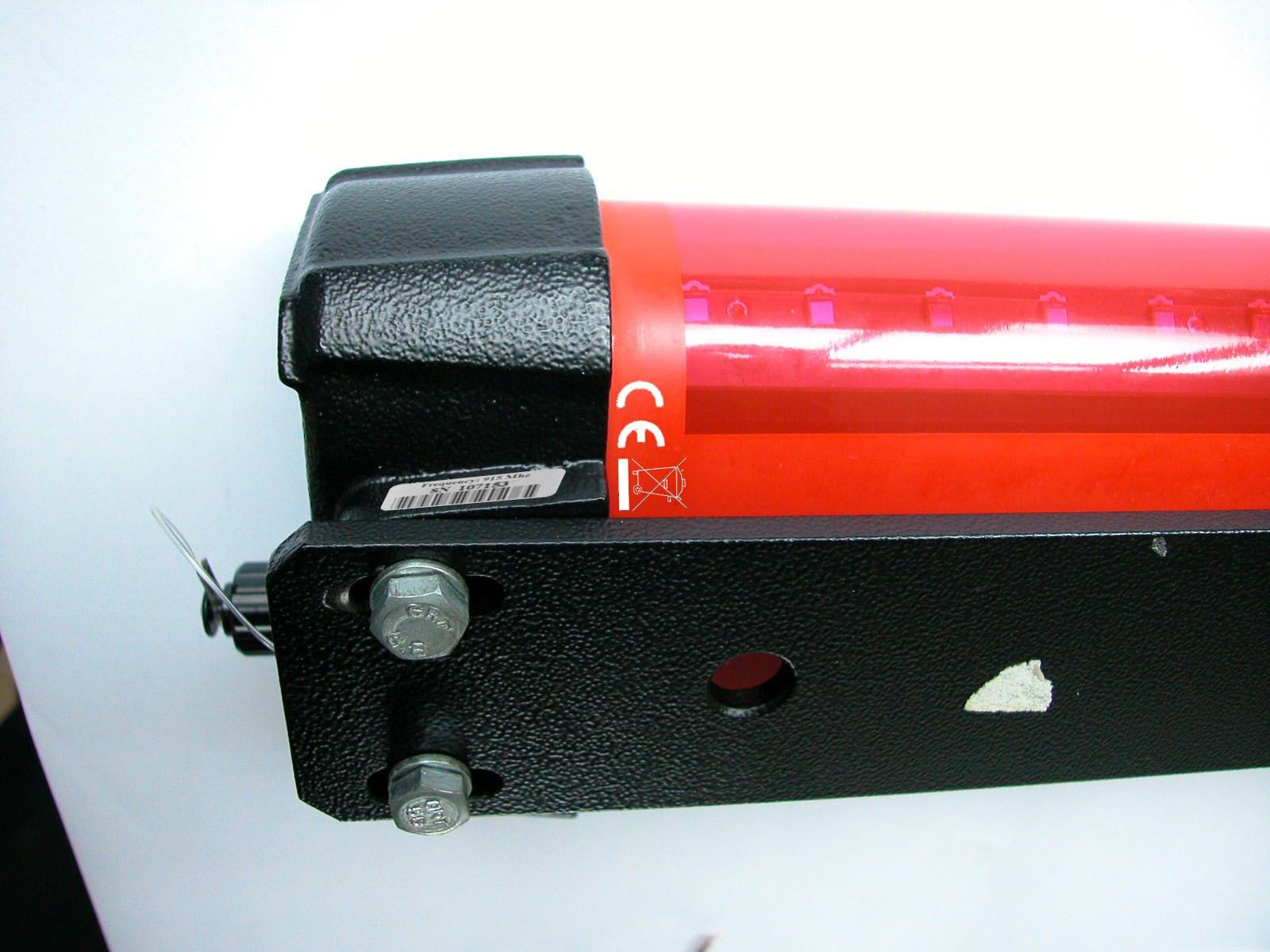
Click to zoom
Application Details
- Equipment Class
- DSC - Part 15 Security/Remote Control Transmitter
- Date of Grant
- Nov 22, 2005
- Application Purpose
- Original Equipment
- Date of Application
- Jul 19, 2005
- Equipment Note
- MR360R Receiver
- Frequency Range
- 915.42000000 - 915.42000000
- Company
- AGL Corporation
- Country
- United States
Documents & Files
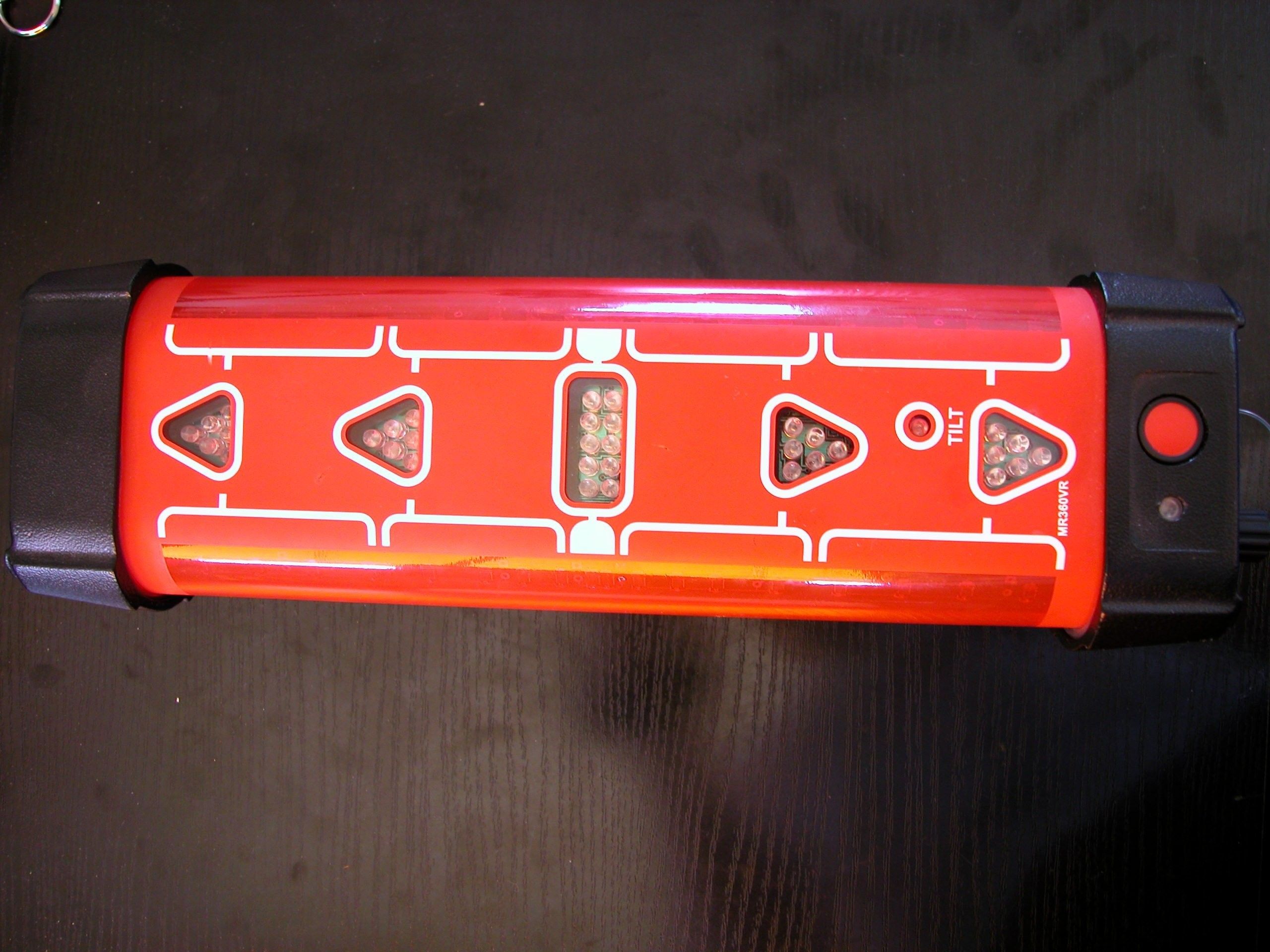
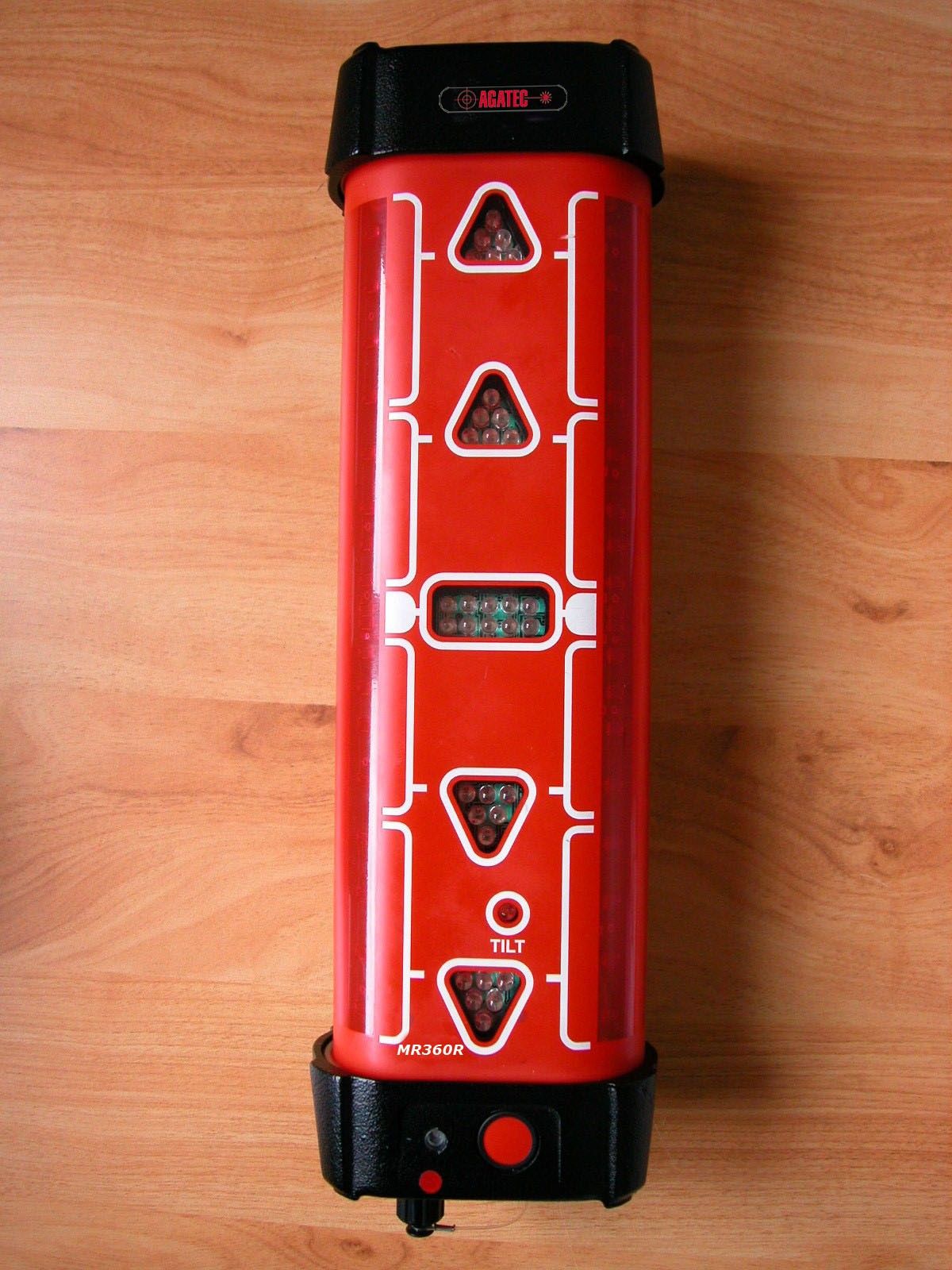
Document Text
Text extracted from the exhibit documents filed with the FCC. Open a document above to read the original.
Users Manual
- 1 - MR360R Operating Manual Manuel d’ utilisation - 2 - WARRANTY/ GARANTIE The manufacturer warrants its measuring instruments against all manufacturing defects for a period of one year from the date of purchase. If during the warranty period, the product is considered as defective by the manufacturer, the latter will decide whether to repair or exchange the product. The only obligation and sole recourse of the buyer will be limited to this repair or exchange.The manufacturer, the distributor or the retailer will in no case be responsible for any incident or consequence, damage,etc,relative to the use of those instruments. LIMITS & EXCLUSIONS: the warranty will not apply to any damage resulting from negligence, accident, misuse, repair or storage, or in case of abnormal use. Les fabricants garantissent les instruments de mesure qu’ils fabriquent contre tous vices de production pour une période d’un an à compter de la date d’achat. Si pendant cette période de garantie un instrument est prouvé défectueux au fabricant, il sera réparé ou remplacé au choix du fabricant. L’unique obligation et le seul recours de l’acheteur ou de loueur seront limités à cette réparation ou ce remplacement. Le fabricant, le distributeur ou le revendeur ne seront en aucun cas responsables pour aucun incident ou conséquence, dommage, etc., relatifs à l’utilisation de ces instruments. LIMITES & EXCLUSIONS : la garantie ne s’applique pas à tous les défauts résultant d’une négligence, accidents, dommage, mauvaise utilisation, réparation ou stockage, ou a tout autre usage autre que l’utilisation normale. - 3 - Description The MR360R is a laser cell of reception especially conceived for all your machine control applications. Accurate, reliable, robust and waterproof, it will be bear at the difficult conditions of the building sites . It detects the beam from visible or infrared laser. Four large detection windows pick up the beam on 360 degrees with a range of 25 cm. Using the MR360R Press the red ‘On/Off’ button on the bottom of the receiver. Each led will blinks in sequence as a self test. The receiver will be in coarse mode. To change the accuracy to fine mode, press again the red ‘On/Off’ button. The two leds located each side of the center led will blink 3 times simultaneously. To turn off the receiver, keep the red ‘On/Off’ button pressed during 3 seconds. Leds will blink from the center to the two extremities. Attachment For quick setup from the machine, the receiver can be ordered with two adjustable clamps or with magnets. The clamps on the MR360R can be attached to a round pipe with a minimum diameter of 40 mm. Power The MR360R receiver is equipped with rechargeable battery (NiCd type). A 110V/240V charger is included. Charging time is 16 hours. - 4 - Positioning the MR360R for excavating MR360R with clamps: The beam of the shovel must equipped with a support (tube of ∅ 40 mm and length 100 cm minimum) be assembled and welded onto mounting feet to 150 cm of the beam. You can also use our magnetic medium SM400 (in option) which will allow you a fast assembly, or to change shovel into a few minutes. - Using your rotary laser and of its cell of manual reception, to dig and determine the sub grade of your earthwork. - To position the beam vertically and to pose the dish of the cup at the coast previously given . - You can carry out your earthwork: to take your points of control, it will always be necessary to vertically position your beam and your cup flat (in the initial position of your adjustment) MR360RA (magnets): The MR360RA avoids the assembly of a support on the beam of the shovel, but the adjustment on the central indicator is more difficult to carry out because of the power of the magnets. It is thus advised to show the laser on a tripod with toothed rack in order to more easily regulate the beam on the central indicator of the cell. - The remainder of the procedure will remain identical to the MR360R with clamps. - 5 - MD360R Remote display The MR360R receiver can be connected to the MD360R remote display inside the cabin thanks to a radio frequency communication. This system is conforming to the European standard R&TTE and American standard FCC: This device complies with Part 15 of the FCC Rules. Operation is subject to the following two conditions: (1) this device may not cause harmful interference, and (2) this device must accept any interference received, including interference that may cause undesired operation. It allows a low cost and an easier installation (wireless). Place the remote display inside the cabin. It allows you to view the led arrows without taking your eyes off your machine’s cutting edge. - 6 - Working from a cab display also allows you to position the MR360R higher, above the cab. This prevents the cab from blocking the laser signal and ensures 360 degrees reception. As soon as you turn on the MD360R, the communication with the MR360R will be detected. You can stop the MR360R pressing 2 seconds on MD360R On/Off button. Specifications Range 200 meters with Agatec lasers Accuracy Fine: +/- 3mm to +/- 12mm Coarse: +/- 5mm to +/- 25mm Accuracy depends on beam diameter. Reception height 25 cm detection window Reception angle 360 degrees Charging time 16 hours Autonomy of MR360R receiver From 12 to 15 hours following the time of load and the ambient temperature during the use Report display connection Using 12/ Volts cable supplied with car lighter connector Radio limited distance 6 m (between MR360R and MD360R) - 7 - Type of attachment MR360R: clamps OR magnets MD360R: suction pods Size MR360R: 375 x 75 x 107mm (w/o clamps) 375 x 75 x 200 mm (with clamps) MD360R: 105 x 20 x 197 mm Weight MR360R: 1, 8 Kg (w/o clamps) MD360R: 0.250 kg - 8 - Description La MR360R est une cellule de réception laser spécialement conçue pour le guidage d’engin. Précise, fiable, robuste et étanche, elle saura résister aux conditions difficiles des chantiers. La MR360R détecte les rayons laser visibles ou …
Text truncated - open the document above for the full version.
Block Diagram
Sensors 5xAmplifier Radio Module RMCx 9 Processor Level Measuring Pover Supply ON/OFF Button Accumulator Led Display MR360R Led Display Pover Supply ON/OFF Button 12/24V DC Cigarette Lighter Connector Processor Radio Unit MD360R
Operational Description
MR360R The MR360R laser receiver can be turned on by pressing the on button. The LED Display will turn on. In this case the receiver is in Narrow mode. By pressing the on button, the high and low leds will blinking, showing that the receiver is in wide measuring mode. Pressing once more the on button, the near-high and near-low leds will blinking, showing that the receiver is in narrow measuring mode. Pressing the on button for more than 2 secs., the receiver will turn off. If the receiver do not receives laser for approximately 2 hours, will turn off. If the batteries are discharged, the receiver will turn off. The laser beam is received with a series of detectors, and amplified with 5 different amplifiers. This signals are then measured and evaluated by the processor, and the led display is set in function of these signals. The Level measuring unit measures the level with a vial and one led and two IR receivers. The level data is transferred to the processor and the led display shows the level information. The power supply transforms the voltage of accumulator to 5V for supplying the 5 amplifiers and processor and to 3.3V for Radio Module. The power supply also contains 3 constant current generators for the led display and an accumulator-charging unit. Every LED change (turning on or off) will be transmitted by the radio module to the MD360R. The data transmitted contains all leds information, witch is turned on or off. ----------------------------------------------------------------------- MD360R The MD 360R contains a radio receiver/transmitter, a processor, power supply unit and led display unit. The data received from MR360R is transmitted from Radio Module to processor, and the led display is set in function of this data. The Power supply transforms the input voltage to 3.3Volts for processor and for the Radio Module. This power supply unit also contains a constant current generator for the led display. The Radio Module is always in receive mode, but pressing the ON button, the MD360R will transmit data to MR360R to turn on or off the led display of MR360R, or data to turn off the MR360R.
Test Report
EMITECH RC-05-42043-1-A – Edition 0 Page 2 TEST CERTIFICATION FOR: Fcc Certification NAME OF THE EQUIPMENT UNDER TEST: RECEIVER AND TRANSMITTER RF CELL TO A REPORT CABINE MR360 & RC360 NAME OF THE MANUFACTURER: AGATEC ADDRESS OF THE APPLICANT: Company : AGATEC Address : 31 boulevard Littré 78600 LE MESNIL LE ROI FRANCE Person in charge : Mr GARCIA DATES OF TEST: 2005, the 23 rd and 24 th of June TESTS LOCATIONS: EMITECH laboratory in Montigny le Bretonneux (78) - FRANCE Open area test site in Aunainville (28) - FRANCE TESTS OPERATOR: B. PELLERIN EMITECH RC-05-42043-1-A – Edition 0 Page 3 TABLE OF CONTENTS 1. INTRODUCTION _______________________________________________________ 4 2. REFERENCE DOCUMENT ______________________________________________ 4 3. EQUIPMENT UNDER TEST (EUT) CONFIGURATION______________________ 4 4. SUMMARY OF TEST RESULTS __________________________________________ 6 5. INTENTIONAL RADIATED EMISSIONS IN THE BAND 40.66 – 40.70 AND ABOVE 70 MHZ ________________________________________________________ 7 6. INTENTIONAL RADIATED EMISSIONS IN THE BAND 30 MHZ – 1 GHZ ____ 10 7. MEASUREMENT OF CONDUCTED EMISSION ON AC MAINS PORTS______ 14 Annex: Customer’s questionnaire EMITECH RC-05-42043-1-A – Edition 0 Page 4 1. INTRODUCTION This document submits the results of Electromagnetic Compatibility tests performed on the equipment «RECEIVER AND TRANSMITTER RF CELL TO A REPORT CABINE MR360 & RC360» herein referred to as the EUT, according to the document listed below. 2. REFERENCE DOCUMENT FCC Part 15 Edition 2005: Code of federal regulations Title 47- Telecommunication Chapter 1- Federal Communication Commission Part 15- Radio frequency devices Subpart B- Unintentional Radiators Limits and methods of measurement of radio disturbance Characteristic of information technology equipment. 3. EQUIPMENT UNDER TEST (EUT) CONFIGURATION See photographs next page. See customer’s questionnaire in annex. See antenna factors, insertion losses and amplifier values in annex. Modification of the equipment during the tests: No. EMITECH RC-05-42043-1-A – Edition 0 Page 5 Photographs of the equipment under test (EUT) EMITECH RC-05-42043-1-A – Edition 0 Page 6 4. SUMMARY OF TEST RESULTS The following table summarizes test results of the EUT. Test results Designation of test Pass Fail N.A. N.P. Comments Intentional radiated emissions in the band 9 kHz – 0.49 MHz X Section 15.209 Intentional radiated emissions in the band 40.66 MHz – 40.70 MHz and above 70 MHz X Section 15.231 Modulation bandwidth in the band 915 MHz X Section 15.231 Unintentional radiated emissions in the band 9 kHz - 30 MHz X Section 15.209 Unintentional radiated emissions in the band 30 MHz – 1 GHz X Section 15.209 Conducted emissions on AC mains ports X Section 15.207 N.A.: Not Applicable N.P.: Not Performed In emission : The tested sample "RECEIVER AND TRANSMITTER RF CELL TO A REPORT CABINE MR360 & RC360” complies with the requirements of the standard: ¾ FCC PART 15 Edition 2005 according to the limits specified in the present report. EMITECH RC-05-42043-1-A – Edition 0 Page 7 5. INTENTIONAL RADIATED EMISSIONS IN THE BAND 40.66 to 40.70 AND ABOVE 70 MHZ Standard: FCC PART 15 Edition 2005 Section: 15.231 Equipment under test arrangement Category of equipment: Table-top equipment The equipment under test (EUT) is placed on a non-conductive test table at 0.8 m above the horizontal metal ground plane. Antenna height is 1 m above the ground plane. For each frequency corresponding to an emission, EUT carried out a rotation through 360° with the aid of the turntable, with the aim to find the maximum of signal. The test antenna is oriented in two orientations (perpendicular or parallel). Only the highest level is recorded. Frequency range : 40.66 – 40.70 and above 70 MHz. Detection mode : Average. Resolution bandwidth : 9 kHz. Measurement distance : 10 meters. EMITECH RC-05-42043-1-A – Edition 0 Page 8 Results : EMITECH RC-05-42043-1-A – Edition 0 Page 9 EMITECH RC-05-42043-1-A – Edition 0 Page 10 6. INTENTIONAL RADIATED EMISSIONS IN THE BAND 30 MHZ – 1 GHZ Standard: FCC PART 15 Edition 2005 Section: 15.209 Equipment under test arrangement Category of equipment : Table-top equipment The equipment under test (EUT) is placed on a non-conductive test table at 0.8 m above the horizontal metal ground plane. For maximum meter reading at each frequency, the antenna height is adjusted between 1 m and 4 m above the ground plane. A 360 degrees rotation of the EUT is performed in vertical and horizontal polarization. The frequency azimuth and antenna height are presented in the tables on the next pages. Frequency range : 30 MHz – 1 GHz. Detection mode : Quasi-Peak Resolution bandwidth : 120 kHz (for 30 MHz – 1 GHz) Measurement distance : 10 meters (for 30 MHz – 1 GHz) Limit : The EUT must satisfy requirements of the section 15.209 as shown in table below. Frequency range (MHz) Limit for Class B (dBμV/m) 30 to 88 30.0 88 to 216 33.5 216 to 960 36.0 960 to 1000 44.0 Operating mode during the test: Normal mode. EMITECH RC-05-42043-1-A – Edition 0 Page 11 Instrumentation test list: Meter N r Emitech Category Mark Type 187 16/004 OATS Emitech Site champ libre 1057 02/045 Receiver Rohde & Schwarz ESVP 1097 18/082 Filter Trilithic 6HC1300-2.5-KK 1144 24/195 Biconical antenna Schwarzbeck VHBA 9123 2150 03/135 Harmonics/Flicker analyser Schaffner Profline 2115-400 2152 03/136 Harmonics/Flicker analyser Schaffner Profline 2115-400 2160 02/066 Spectrum analyzer Agilent Technologies E7405A 2862 35/239 Câble Câbles & Connectiques N-2m 2864 35/241 Câble Câbles & Connectiques N-SMA 3106 24/571 Antenna Schwarzbeck UHALP 9108 3229 01/127 Amplifier Miteq AMF-6D-010250-70-7P 3374 24/604 Antenna Emco 3115 Results : Table reference Comments Table 1 Measurement in vertical polarization Table 2 Measurement in horizontal polarization Observation during the test : The equipment complies with the requirements of the standard FCC PART 15.209 Edition 2005 EMITECH RC-05-42043-1-A …
Text truncated - open the document above for the full version.
Test Report
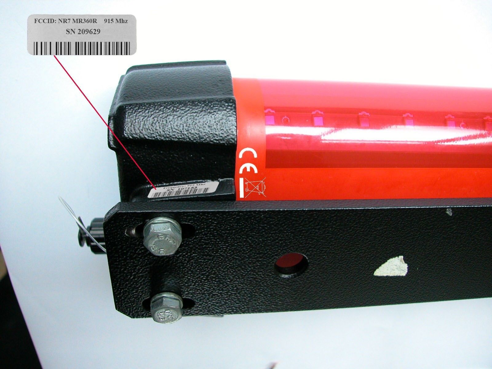
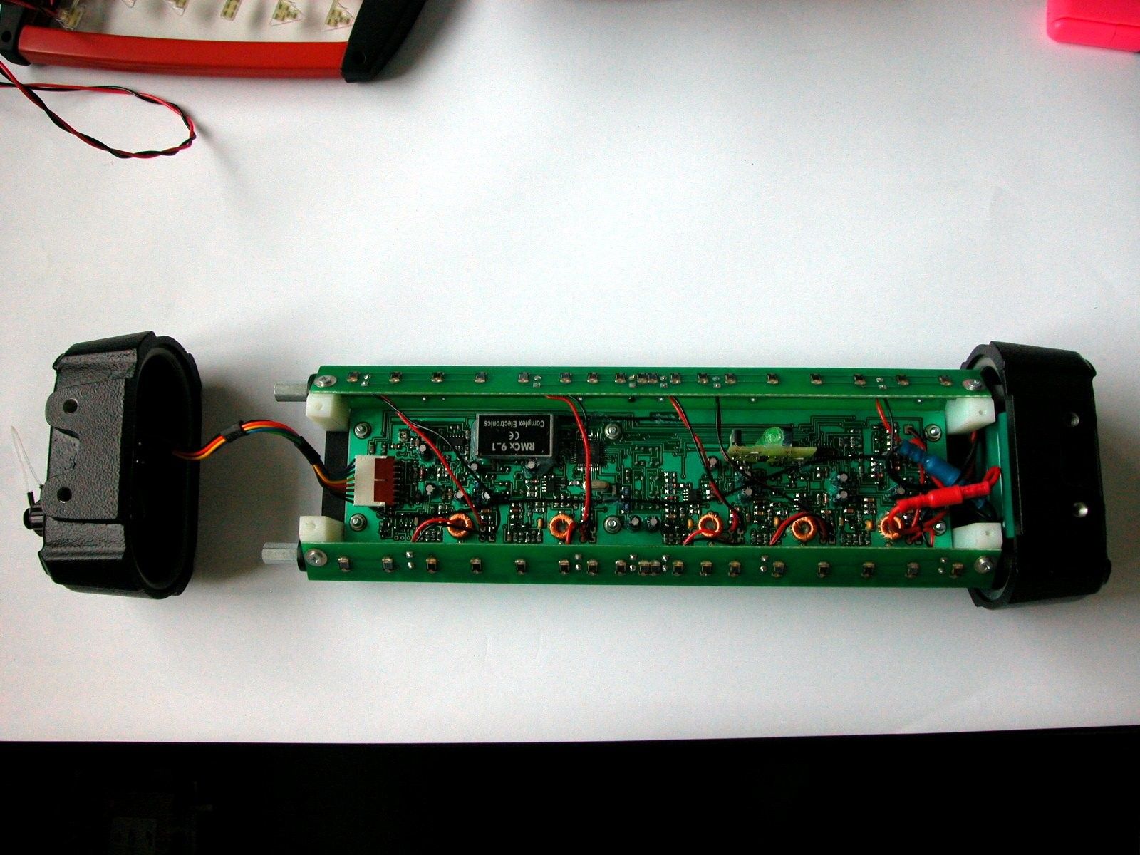
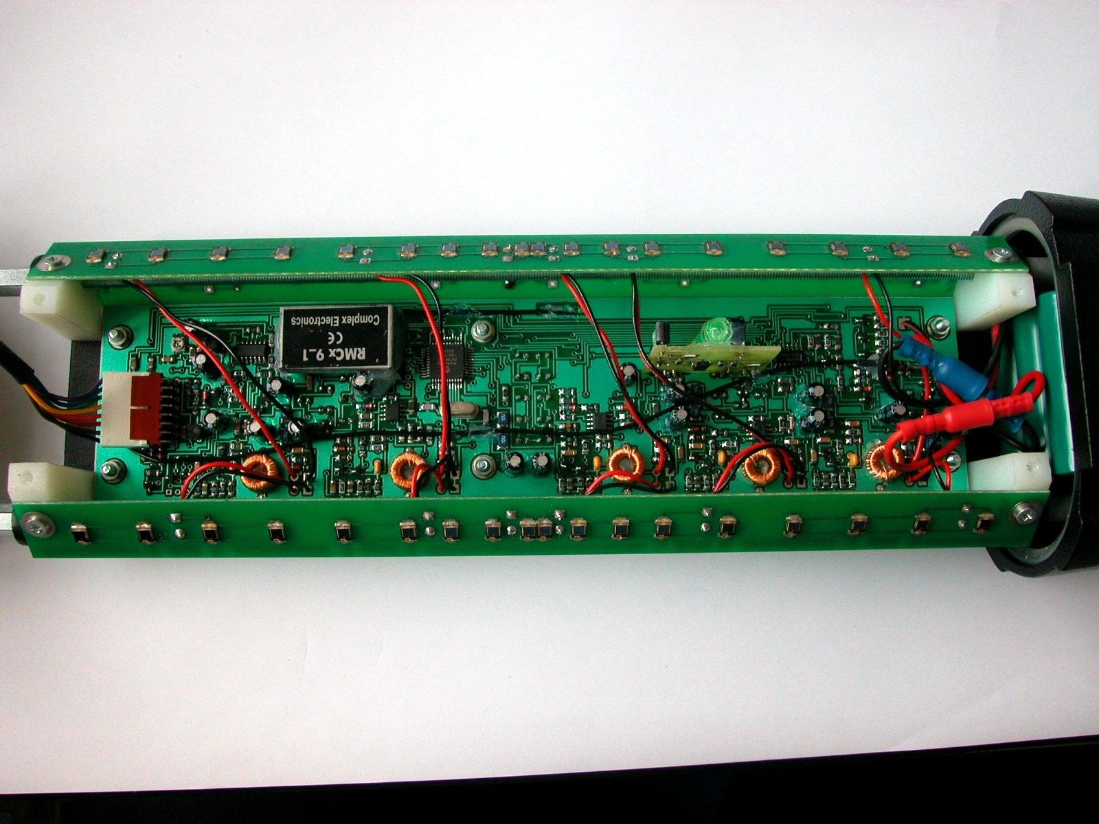
2 / 10 CONTENT 1. GENERAL INFORMATION ___________________________________________________________ 3 2. PRODUCT DESCRIPTION ____________________________________________________________ 4 2.1 Block diagram description ________________________________________________________________ 4 2.2 Photograph of the E.U.T (internal and external photos)______________________________________ 4 2.3 Description of circuit functions (antenna, ground system,... ) __________________________________ 5 2.4 Tested System Details ____________________________________________________________________ 5 3. PRODUCT LABELING _______________________________________________________________ 6 3.1 FCC ID label ____________________________________________________________________________ 6 3.2 Location of label on E.U.T ________________________________________________________________ 6 4. SYSTEM TEST CONFIGURATION _____________________________________________________ 7 4.1 Functioning mode during the test (E.U.T test program) _______________________________________ 7 4.2 E.U.T exercise software ___________________________________________________________________ 7 4.3 Special accessories or peripherals __________________________________________________________ 7 4.4 Equipment modifications to achieve compliance during the test (with photograph) _______________ 8 5. TRANSITION PROVISIONS (15.37)_____________________________________________________ 9 6. ANNEX_____________________________________________________________________________ 9 3 / 10 1. GENERAL INFORMATION NAME OF THE EQUIPMENT UNDER TEST: - Trade name: MR360R Receiver and MD360R Cabin Report - Model number: - Serial number: APPLICANT’S COMPLETE, LEGAL BUSINESS NAME: (the responsible party must be located in USA) FCC Identifier: NR7 ADDRESS OF THE APPLICANT: AGL Address: 2202 Redmond Road P.O. Box 189 Jacksonville, Arkansas 72076 USA U.S.A. Telephone number: +1 (-501) -982-4433 ext 266 Person as the applicant’address: M. LARRY ZAITZ ADDRESS OF THE MANUFACTURER: Company: AGATEC Address: 21 Bd du Littré 78 600 Le MESNIL LE ROI EQUIPEMENT SPECIFICATION: - Equipment class: X Receiver Intentional Radiator Non Intentional Radiator - Frequency range (List of clock upper to 9 kHz): 20 Mhz for MR360R and 11,0592Mz for RC360R - Consumed power: MR360R : 0,37 W, RC360R : 2W 4 / 10 2. PRODUCT DESCRIPTION 2.1 Block diagram description MR360R Receiver The power supply transforms the voltage of accumulator to 5V for supplying the 5 amplifiers and processor and to 3.3V for Radio Module. The power supply also contains 3 constant current generators for the led display and an accumulator-charging unit. The laser beam is received with a series of detectors, and amplified with 5 different amplifiers. This signals are then measured and evaluated by the processor, and the led display is set in function of these signals. The Level measuring unit measures the level with a vial and one led and two IR receivers. The level data is transferred to the processor and the led display shows the level information called “TILT”. Every LED change (turning on or off) will be transmitted by the radio module to the MD360R. The data transmitted contains all leds information, witch is turned on or off. . MR360R Receiver The MD 360R contains a radio receiver/transmitter, a processor, power supply unit and led display unit. The Power supply transforms the input voltage to 3.3Volts for processor and for the Radio Module. This power supply unit also contains a constant current generator for the led display. The data received from MR360R is transmitted from Radio Module to processor, and the led display is set in function of this data. The Radio Module is always in receive mode, but pressing the ON button, the MD360R will transmit data to MR360R to turn on or off the led display of MR360R, or data to turn off the MR360R 2.2 Photograph of the E.U.T (internal and external photos) - Showing exterior appearance, the construction, the component placement and the chassis assembly, the antenna. See attached external photos : - MD360R_external_photo1.jpg and MD360R_external_photo2.jpg - MR360R_external_photo1.jpg and MR360R_external_photo2.jpg and See attached internal photos : - MD360R_internal_photo1.jpg - MR360R_internal_photo1.jpg , MR360R_internal_photo2.jpg and MR360R_internal_photo1.jp 5 / 10 2.3 Description of circuit functions (antenna, ground system,... ) See paragraph 2.1 2.4 Tested System Details Model Number (serial number) FCC ID (assembled from tested components) Description I/O Port types Cable description (type, lenght) MR360R Receiver MD360R Cabin Report NR7 MR360R NR7 MD360R No cables 1 cable (2 conductors) with lighter connector for power supplier 6 / 10 3. PRODUCT LABELING 3.1 FCC ID label : Receiver : MR360R Cabin Report : MD360R 3.2 Location of label on E.U.T : These FCC ID label will be found into the User Manual (See them in the User Manual annex file) 7 / 10 4. SYSTEM TEST CONFIGURATION 4.1 Functioning mode during the test (E.U.T test program) Normal operating (as describe into the User Manual). 4.2 E.U.T exercise software Receiver MR360R : MR360RV5 version 5, 27 October 2003 Cabin Report MD360R : MD360RV1.2 version 1.2, 20 July 2004 4.3 Special accessories or peripherals N.A 9 / 10 5. TRANSITION PROVISIONS 6. ANNEX 10 / 10 ITEM FILE NAME MD360R Block diagram MD360R Block diagram Blockdiagram_MR360R_MD360R.pdf MD360R External photos MR360R External photos MD360R_external_photo1.jpg MD360R_external_photo2.jpg MR360R_external_photo1.jpg MR360R_external_photo2.jpg MD360R ID Label / location info MR360R ID Label / location info MD360R_ID_label1.jpg MD360R_ID_label2.jpg MR360R_ID_label1.jpg MR360R_ID_label2.jpg MD360R Internal photos MR360R Internal photos MD360R_internal_photo1.jpg MR360R_internal_photo1.jpg MR360R_internal_photo2.jpg MR360R_internal_photo3.jpg MD360R Operational Description MR360R Operational Description MR360R_MD360R_operational_description.pdf MD360R Schematics MR360R Schema…
Text truncated - open the document above for the full version.
Test Setup Photos
Test set up photographs
Contact Information
Applicant
Mr. Larry Zaitz
Technical Contact
Test Firm
EMITECH Ile de FranceDominique Bras
Technical Specifications
| # | Rule Parts | Frequency Range | Power Output |
|---|---|---|---|
| 1 | 15.231 | 915.42 MHz - 915.42 MHz | - |
Other Applications from AGL Corporation
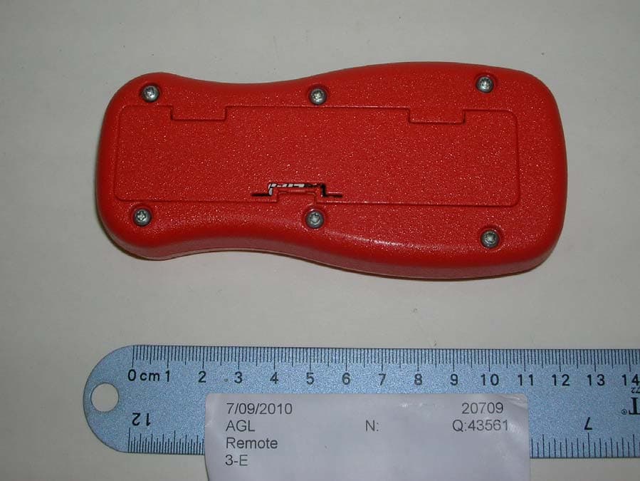
NR7GP15R
Sep 12, 2010Remote Control for Laser Levelling System
Equipment Class
DXT - Part 15 Low Power Transceiver, Rx Verified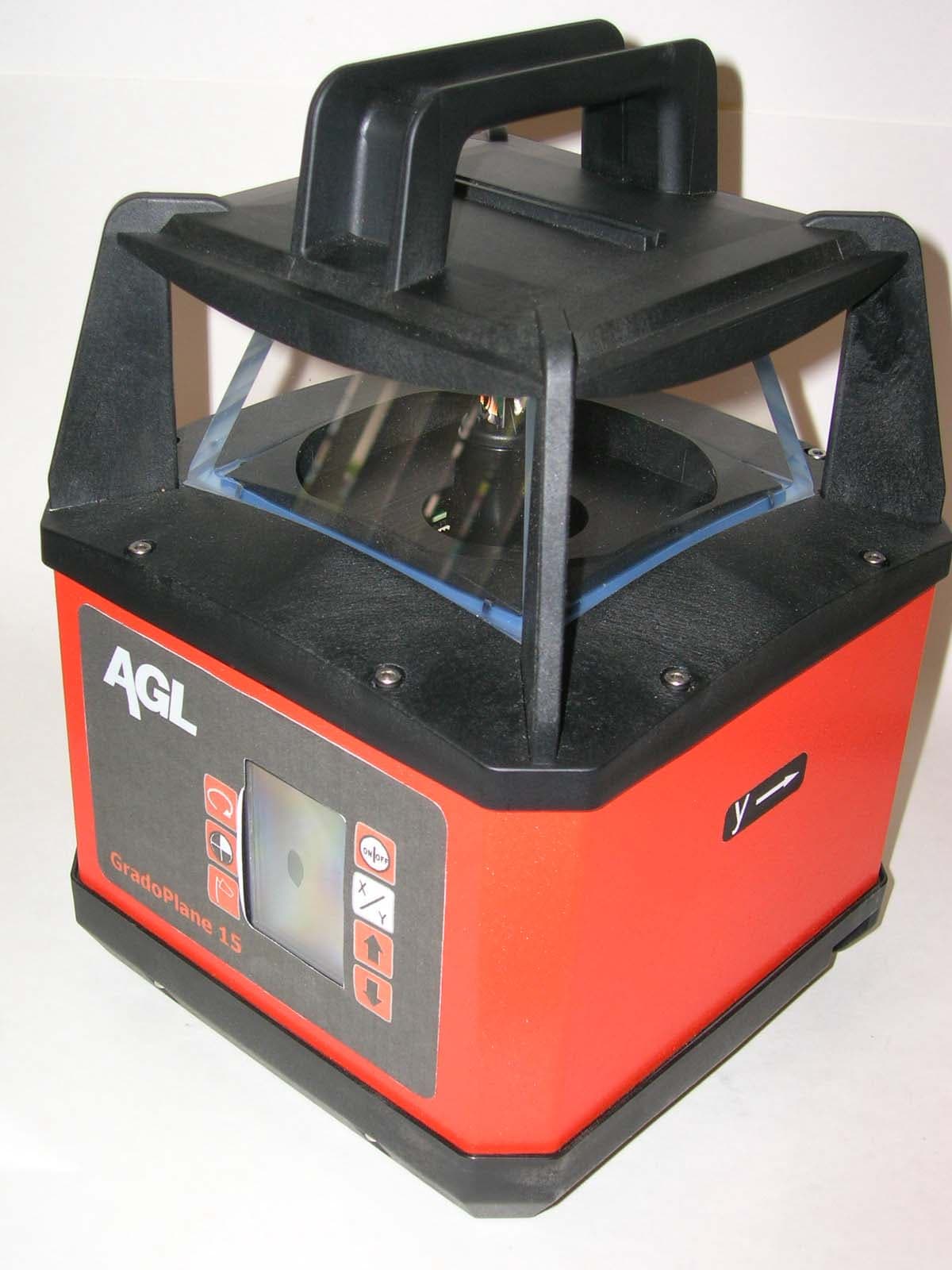
NR7GP15
Sep 12, 2010Laser Levelling System with Remote
Equipment Class
DXT - Part 15 Low Power Transceiver, Rx Verified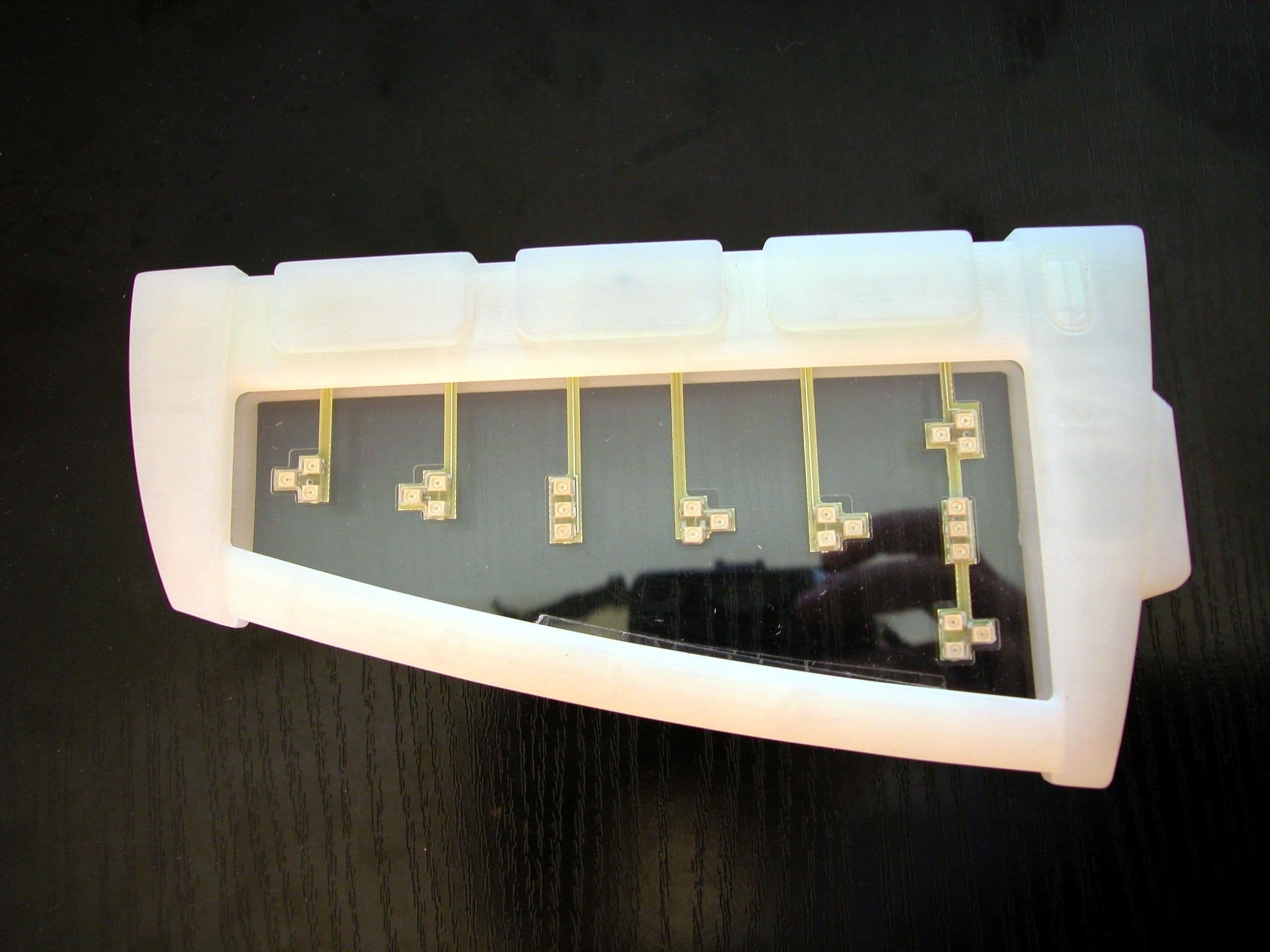
NR7MD360R
Oct 24, 2005MD360R Cabin
Equipment Class
DTS - Digital Transmission System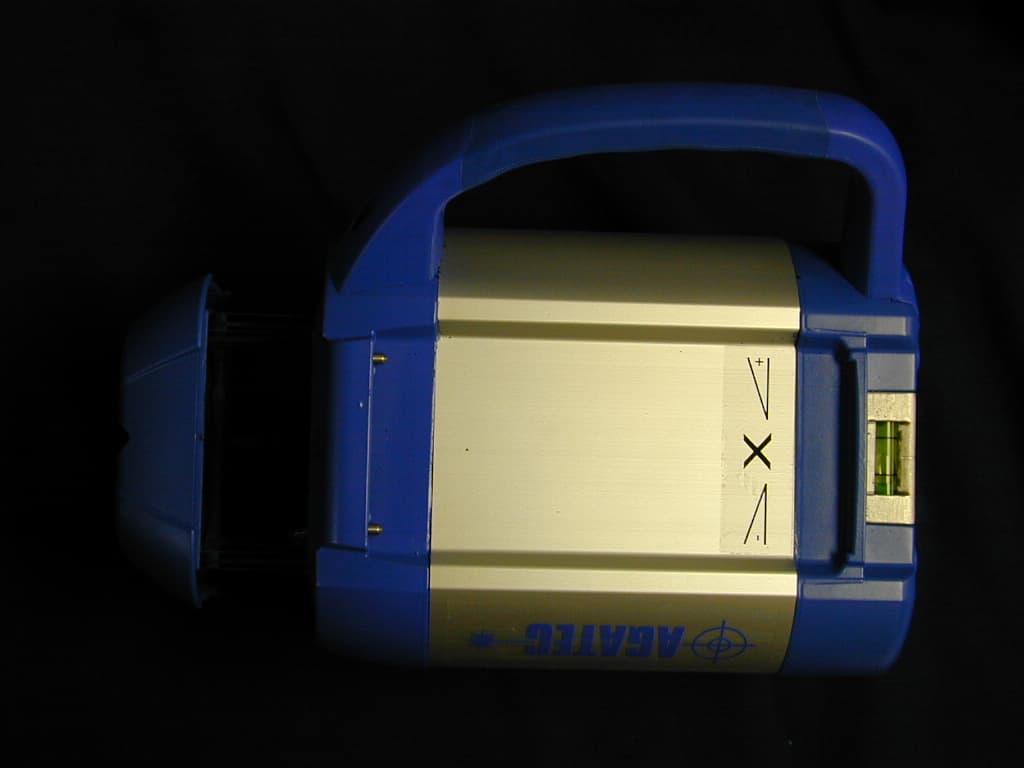
NR7A710
Oct 12, 2004Multipurpose Laser
Equipment Class
DXT - Part 15 Low Power Transceiver, Rx Verified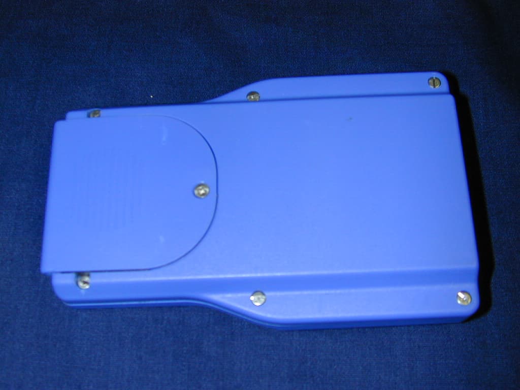
NR7A710HR
Oct 12, 2004Remote Control
Equipment Class
DXT - Part 15 Low Power Transceiver, Rx Verified