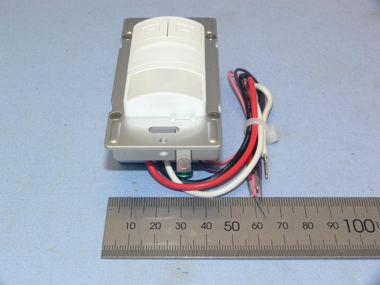
NRIWS270000Line Voltage Dual-Tech Wall Switch Sensor
IR-TEC International Ltd.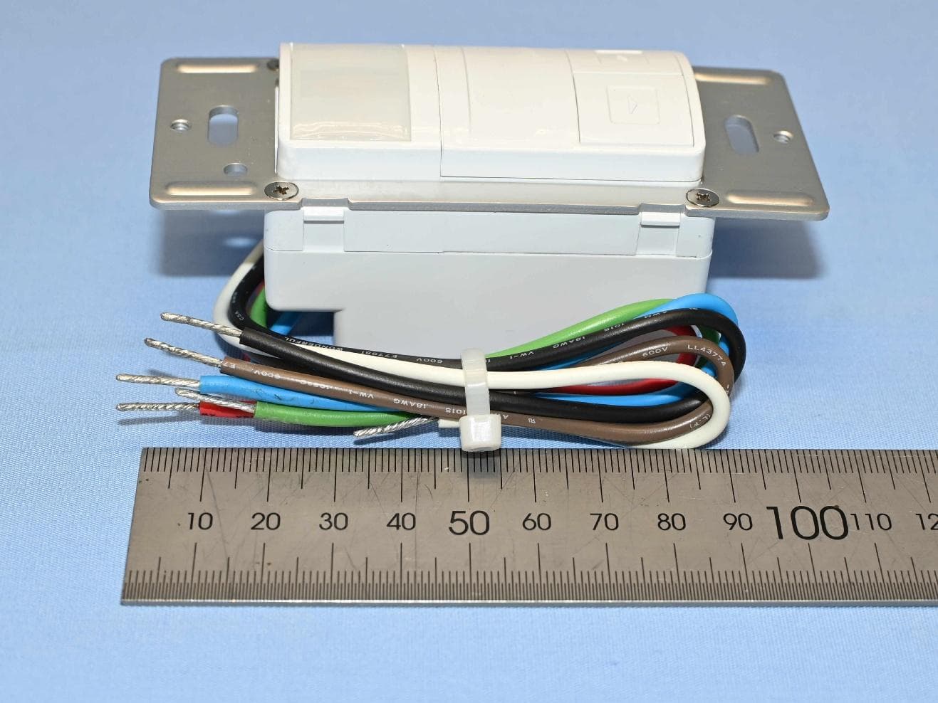
Click to zoom
Application Details
- Equipment Class
- FDS - Part 15 Field Disturbance Sensor
- Date of Grant
- Feb 04, 2026
- Application Purpose
- Original Equipment
- Equipment Note
- Line Voltage Dual-Tech Wall Switch Sensor
- Frequency Range
- 10511.38000000 - 10511.38000000
- Company
- IR-TEC International Ltd.
- Country
- Taiwan
Documents & Files
Document Text
Text extracted from the exhibit documents filed with the FCC. Open a document above to read the original.
Users Manual
OVERVIEW & OPERATION The LDT-700 series is a 2-pole dual technology line voltage wall switch sensor designed to fit in a standard NEMA wall box for automatic lighting control. This state-of-the-art wall switch sensor combines digital Passive Infrared and advanced High Frequency Dopplersensing technologies into an aesthetically pleasing housing to provide excellent occupancy/vacancy sensing performance within its 180° field of view detection range. The LDT-700 contains two relays and two push buttons, for controlling two lighting loads independently. A dual color LED indicates the sensor detection, BLUE for PIR and GREEN for HFD. Pressing the push-button will change the state of relay contacts manually. The sensor provides typical occupancy sensing (Auto-ON, Auto-OFF) control on pole-1 and vacancy sensing (Manual-ON, Auto-OFF) control on pole-2. Different control modes of each pole can be programmed via DIP switch settings. Presentation Mode (PM) allows the occupant to switch OFF the load as desired by pressing the specific push-button. The load will remain OFF if motion is detected before the time delay elapses. Pressing the push-button again will turn the load back ON and the sensor will operate as per sensor setting. If no motion has been detected and the time delay expires, sensor will return to normal operation and turn ON the load with the next sensed motion. INSTALLATION NOTES Line Voltage Dual-Tech Wall Switch Sensor INSTALLATION INSTRUCTIONS LDT-700 series SPECIFICATIONS Power supply Sensing technology Inrush current Load switching Detectable speed Mounting height Ambient light level Delay time setting Op. humidity Op. temperature Dimensions Detection coverage Maximum load, per pole 120/277VAC, 60Hz Digital PIR & High Frequency Doppler Incandescent/Halogen – 800W (VA) Fluorescent Ballast/CFL – 800W (VA) Ballast Electronic (LED) – 500/800VA@120/277V Motor – 1/6 HP Max. 80A, 16.7 ms @60Hz, per pole Zero-cross Hybrid-Switching 1~10 ft./sec. (0.3~3 m/sec) 3~5 ft. (90~150 cm) above the floor Major motion - 30 ft x 40 ft (W x L) @4 ft high Minor motion - 20 ft x 20 ft (W x L) @4 ft high 7 levels, from dark to 24 Hour T/1’/3’/5’/10’/20’/30’, T=10 sec. for testing Max. 95% RH, non-condensate -40°F ~ 131°F (-40°C ~ 55°C) 4.13”H x 1.77”W x 1.65”D (w/mounting plate) Indoor dry location use only Utilisation a L'interieur Uniquement DETECTION COVERAGE 40’ Top view Side view 4’ 7’ 30’ 40’ Minor motion 20’ 20’ Major motion 180°, 30 ft x 40 ft (W x L) Risk of Electric Shock - Disconnect power supply at the circuit breaker before installing, replacing lamps, or servicing. DO NOT control a load in excess of specified ratings to avoid damaging the sensor or the property. Install and use this sensor in accordance with electrical codes and regulations. This device is intended to be installed by a qualified electrician. DO NOT attempt to service or repair. Install the sensor at least 1ft. away from any occupant. Afin d'eviter tout risque de choc electrique ou electrocution, couper le courant au disjoncteur avant installation, remplacement des lampes ou tout service d'entretien. NE PAS contrôler une charge supérieure à la capacité spécifiée pour éviter d'endommager le capteur ou la propriété. Installer et utiliser ce capteur conformément aux codes et règlements électriques. Ce dispositif est destiné à être installé par un électricien qualifié. NE PAS tenter de réparer. The sensor is more sensitive to the movements “crossing” the detection zones than “toward” or “away” the sensor. To obtain better sensitivity, ensure the sensor to have clear field of view for the occupant’s motion within the desired coverage. The closer movement is to the sensor, the more sensitive the sensor is. The sensor should be mounted within the specified mounting height for optimal performance. Avoid blocking the sensor with any obstacles, such as door, plant, partition or furniture. As a general rule, every occupant within the desired range should be able to clearly see the sensor. Do NOT mount the sensor directly above or nearby a heat source, or where unintended motion (e.g. hallway traffic) will be “seen” by the sensor. 1. 2. 3. 4. 5. P/N: 058-70005-00XPrinted in Taiwanwww.irtec.com This product may be covered by one or more U.S. patents or patent applications. Please visit www.irtec.com for more information. WARNING & CAUTION AVERTISSEMENT & PRUDENCE This device complies with Part 15 of the FCC Rules. Operation is subject to the following two conditions: (1) This device may not cause harmful interference, and (2) this device must accept any interference received, including interference that may cause undesired operation. This equipment has been tested and found to comply with the limits for a Class B digital device, pursuant to Part 15 of the FCC Rules. These limits are designed to provide reasonable protection against harmful interference in a residential installation. This equipment generates, uses and can radiate radio frequency energy and, if not installed and used in accordance with the instructions, may cause harmful interference to radio communications. However, there is no guarantee that interference will not occur in a particular installation. If this equipment does cause harmful interference to radio or television reception, which can be determined by turning the equipment off and on, the user is encouraged to try to correct the interference by one of the following measures: -Reorient or relocate the receiving antenna. -Increase the separation between the equipment and receiver. -Connect the equipment into an outlet on a circuit different from that to which the receiver is connected. -Consult the dealer or an experienced radio/TV technician for help. FCC Caution: Any changes or modifications not expressly approved by the party responsible for compliance could void the user's authority to operate this equipment. This transmitter must not be co-located or operating in conjunction with any other antenna or transmitte…
Text truncated - open the document above for the full version.
Attestation Statements
Date:2026-01-16 FCC ID:NRIWS270000 To the attention of Federal Communications Commission Authorization and Evaluation Division Attestation Statements Attestation Statements Part 2.911(d)(5)(i) Filing IR-TEC International Ltd. certifies that the equipment for which authorization is sought is not “covered” equipment prohibited from receivingan equipment authorization pursuant to section 2.903 of the FCC rules. Attestation Statements Part 2.911(d)(5)(ii) Filing IR-TEC International Ltd.certifies that, as of the date of the filing of the application, the applicantis not identified on the Covered List as an entity producing “covered” equipment. Sincerely yours, ----------------------------------------------- Name: Jerry Lin / Title: Manager IR-TEC International Ltd. Tel: 886-3-2221788*400 Fax: 886-3-2221488 E-mail: [email protected]
Cover Letter(s)
Date:2026-01-16 FCC ID:NRIWS270000 To the attention of Federal Communications Commission Authorization and Evaluation Division Permanent Confidentiality Request Pursuant to Sections 0.457 and 0.459 of the Commission’s Rules, the Applicant hereby requests confidential treatment of information accompanying this Application as outlined below: Schematics Block Diagram Operational Description The above materials contain trade secrets and proprietary information not customarily released to the public. The public disclosure of these matters might be harmful to the Applicant and provide unjustified benefits to its competitors. The Applicant understands that pursuant to Rule 0.457, disclosure of this Application and all accompanying documentation will not be made before the date of the Grant for this application. Sincerely yours, ----------------------------------- Name: Jerry Lin / Title: Manager IR-TEC International Ltd. Tel: 886-3-2221788*400 Fax: 886-3-2221488 E-mail: [email protected]
Cover Letter(s)
Date: 2026-01-22 FCC ID:NRIWS270000 A U T H O R I Z A T I O N L E T T E R To Whom It May Concern: IR-TEC International Ltd. hereby authorizes Emerald Chen / Specialist of Bureau Veritas Consumer Products Services (H.K.) Ltd., Taoyuan Branch(“BV CPS Taoyuan”),to act on its behalf in all matters relating to the Federal Communication Commission (“FCC”) application for equipment authorization in connection with the FCC ID listed above, including signing of all documents relating to these matters. Any and all acts carried out byEmerald Chen / Specialistof BV CPS Taoyuan on IR-TEC International Ltd.’s behalf, within the scope of the powers granted herein, shall have the same effect as acts of its own. If you have any questions regarding the authorization, please don’t hesitate to contact us. Sincerely yours, ----------------------------------------------- Name: Jerry Lin / Title: Manager IR-TEC International Ltd. Tel: 886-3-2221788*400 Fax: 886-3-2221488 E-mail: [email protected]
External Photos
Reference No.: BCOR-WTW-P24100231_EXT Page No. 1/4 CONSTRUCTION PHOTOS OF EUT Reference No.: BCOR-WTW-P24100231_EXT Page No. 2/4 Reference No.: BCOR-WTW-P24100231_EXT Page No. 3/4 Reference No.: BCOR-WTW-P24100231_EXT Page No. 4/4
ID Label/Location Info
FCC ID:NRIWS270000 The label will be permanently affixed and readily visible. Back of EUT Label location
Internal Photos
Reference No.: BCOR-WTW-P24100231_INT Page No. 1/7 CONSTRUCTION PHOTOS OF EUT Reference No.: BCOR-WTW-P24100231_INT Page No. 2/7 Reference No.: BCOR-WTW-P24100231_INT Page No. 3/7 RF Chip Reference No.: BCOR-WTW-P24100231_INT Page No. 4/7 Reference No.: BCOR-WTW-P24100231_INT Page No. 5/7 Reference No.: BCOR-WTW-P24100231_INT Page No. 6/7 Antenna Reference No.: BCOR-WTW-P24100231_INT Page No. 7/7
RF Exposure Info
Report No.: MFBCOR-WTW-P24100231 Page No. 1 / 6 Report Format Version: 6.1.1 Reference No.: CEPG-WTW-P22030025 RF Exposure Report Report No.: MFBCOR-WTW-P24100231 FCC ID: NRIWS270000 Test Model: LDT-700SW Series Model: LD(X) -70(Y)S(Z), X can be S or T, Y can be 0 ~ 9, Z can be A~Z (denotes housing color) Received Date: 2024/10/15 Date of Evaluation: 2026/1/8 Issued Date: 2026/2/2 Applicant: IR-TEC International Ltd. Address: 6 Rong An Road, Luzhu Taoyuan 33852, TAIWAN Issued By: Bureau Veritas Consumer Products Services (H.K.) Ltd., Taoyuan Branch Lin Kou Laboratories Lab Address: No. 47-2, 14th Ling, Chia Pau Vil., Lin Kou Dist., New Taipei City, Taiwan Test Location: No. 19, Hwa Ya 2nd Rd., Wen Hwa Vil., Kwei Shan Dist., Taoyuan City 33383, TAIWAN FCC Registration / Designation Number: 788550 / TW0003 This report is governed by, and incorporates by reference, the Conditions of Testing as posted at the date of issuance of this report at http://www.bureauveritas.com/home/about-us/our-business/cps/about-us/terms-conditions/ and is intended for your exclusive use. Any copying or replication of this report to or for any other person or entity, or use of our name or trademark, is permitted only with our prior written permission. This report sets forth our findings solely with respect to the test samples identified herein. The results set forth in this report are not indicative or representative of the quality or characteristics of the lot from which a test sample was taken or any similar or identical product unless specifically and expressly noted. Our report includes all of the tests requested by you and the results thereof based upon the information that you provided to us. Measurement uncertainty is only provided upon request for accredited tests. Statements of conformity are based on simple acceptance criteria without taking measurement uncertainty into account, unless otherwise requested in writing. You have 60 days from date of issuance of this report to notify us of any material error or omission caused by our negligence or if you require measurement uncertainty; provided, however, that such notice shall be in writing and shall specifically address the issue you wish to raise. A failure to raise such issue within the prescribed time shall constitute your unqualified acceptance of the completeness of this report, the tests conducted and the correctness of the report contents. Report No.: MFBCOR-WTW-P24100231 Page No. 2 / 6 Report Format Version: 6.1.1 Reference No.: CEPG-WTW-P22030025 Table of Contents Release Control Record .................................................................................................................................. 3 1 Certificate of Conformity ...................................................................................................................... 4 2 RF Exposure .......................................................................................................................................... 5 2.1 Limits for Maximum Permissible Exposure (MPE) .............................................................................. 5 2.2 MPE Calculation Formula ................................................................................................................... 5 2.3 Classification ....................................................................................................................................... 5 3 Calculation Result ................................................................................................................................ 6 Report No.: MFBCOR-WTW-P24100231 Page No. 3 / 6 Report Format Version: 6.1.1 Reference No.: CEPG-WTW-P22030025 Release Control Record Issue No. Description Date Issued MFBCOR-WTW-P24100231 Original Release 2026/2/2 Report No.: MFBCOR-WTW-P24100231 Page No. 4 / 6 Report Format Version: 6.1.1 Reference No.: CEPG-WTW-P22030025 1 Certificate of Conformity Product: Line Voltage Dual-Tech Wall Switch Sensor Brand: Test Model: LDT-700SW Series Model: LD(X) -70(Y)S(Z), X can be S or T, Y can be 0 ~ 9, Z can be A~Z (denotes housing color) Sample Status: Engineering Sample Applicant: IR-TEC International Ltd. Date of Evaluation: 2026/1/8 FCC Rule Part: FCC Part 2 (Section 2.1091) Standards: KDB 447498 D01 General RF Exposure Guidance v06 The above equipment has been tested by Bureau Veritas Consumer Products Services (H.K.) Ltd., Taoyuan Branch, and found compliance with the requirement of the above standards. The test record, data evaluation & Equipment Under Test (EUT) configurations represented herein are true and accurate accounts of the measurements of the sample’s RF characteristics under the conditions specified in this report. Prepared by : , Date: 2026/2/2 Vera Huang / Specialist Approved by : , Date: 2026/2/2 Jeremy Lin / Project Engineer Report No.: MFBCOR-WTW-P24100231 Page No. 5 / 6 Report Format Version: 6.1.1 Reference No.: CEPG-WTW-P22030025 2 RF Exposure 2.1 Limits for Maximum Permissible Exposure (MPE) Frequency Range (MHz) Electric Field Strength (V/m) Magnetic Field Strength (A/m) Power Density (mW/cm 2 ) Average Time (minutes) Limits For General Population / Uncontrolled Exposure 300-1500 ... ... F/1500 30 1500-100,000 ... ... 1.0 30 F = Frequency in MHz 2.2 MPE Calculation Formula Pd = (Pout*G) / (4*pi*r 2 ) where Pd = power density in mW/cm 2 Pout = output power to antenna in mW G = gain of antenna in linear scale pi = 3.1416 r = distance between observation point and center of the radiator in cm 2.3 Classification The antenna of this product, under normal use condition, is at least 20cm away from the body of the user. So, this device is classified as Mobile Device. Report No.: MFBCOR-WTW-P24100231 Page No. 6 / 6 Report Format Version: 6.1.1 Reference No.: CEPG-WTW-P22030025 3 Calculation Result Evaluation Frequency (GHz) Max EIRP Power (dBm) Max EIRP Power (mW) Distance (cm) Power Density (mW/cm 2 ) Limit (mW/cm 2 ) Result 10.51138 -15.56 0.0278 2…
Text truncated - open the document above for the full version.
Test Report
Report No.: RFBCOR-WTW-P24100231 Page No. 1 / 34 Report Format Version: 6.1.1 Reference No.: CEPG-WTW-P22030025 FCC Test Report Report No.: RFBCOR-WTW-P24100231 FCC ID: NRIWS270000 Test Model: LDT-700SW Series Model: LD(X) -70(Y)S(Z), X can be S or T, Y can be 0 ~ 9, Z can be A~Z (denotes housing color) (Refer to item 3.1 for the more details) Received Date: 2024/10/15 Test Date: 2025/12/24 ~ 2026/1/5 Issued Date: 2026/2/2 Applicant: IR-TEC International Ltd. Address: 6 Rong An Road, Luzhu Taoyuan 33852, TAIWAN Issued By: Bureau Veritas Consumer Products Services (H.K.) Ltd., Taoyuan Branch Lin Kou Laboratories Lab Address: No. 47-2, 14th Ling, Chia Pau Vil., Lin Kou Dist., New Taipei City, Taiwan Test Location: (1) No. 19, Hwa Ya 2nd Rd., Wen Hwa Vil., Kwei Shan Dist., Taoyuan City 33383, Taiwan (2) No. 70, Wenming Rd., Guishan Dist., Taoyuan City 333, Taiwan (R.O.C.) FCC Registration / Designation Number: (1) 788550 / TW0003 (2) 281270 / TW0032 This report is governed by, and incorporates by reference, the Conditions of Testing as posted at the date of issuance of this report at http://www.bureauveritas.com/home/about-us/our-business/cps/about-us/terms-conditions/ and is intended for your exclusive use. Any copying or replication of this report to or for any other person or entity, or use of our name or trademark, is permitted only with our prior written permission. This report sets forth our findings solely with respect to the test samples identified herein. The results set forth in this report are not indicative or representative of the quality or characteristics of the lot from which a test sample was taken or any similar or identical product unless specifically and expressly noted. Our report includes all of the tests requested by you and the results thereof based upon the information that you provided to us. Measurement uncertainty is only provided upon request for accredited tests. Statements of conformity are based on simple acceptance criteria without taking measurement uncertainty into account, unless otherwise requested in writing. You have 60 days from date of issuance of this report to notify us of any material error or omission caused by our negligence or if you require measurement uncertainty; provided, however, that such notice shall be in writing and shall specifically address the issue you wish to raise. A failure to raise such issue within the prescribed time shall constitute your unqualified acceptance of the completeness of this report, the tests conducted and the correctness of the report contents. Report No.: RFBCOR-WTW-P24100231 Page No. 2 / 34 Report Format Version: 6.1.1 Reference No.: CEPG-WTW-P22030025 Table of Contents Release Control Record .................................................................................................................................. 3 1 Certificate of Conformity ...................................................................................................................... 4 2 Summary of Test Results ..................................................................................................................... 5 2.1 Measurement Uncertainty ................................................................................................................... 5 2.2 Modification Record ............................................................................................................................ 5 3 General Information .............................................................................................................................. 6 3.1 General Description of EUT ................................................................................................................ 6 3.2 Description of Test Modes ................................................................................................................... 6 3.2.1 Test Mode Applicability and Tested Channel Detail ............................................................................. 7 3.3 Duty Cycle of Test Signal .................................................................................................................... 8 3.4 Description of Support Units ............................................................................................................... 8 3.4.1 Configuration of System under Test .................................................................................................... 8 3.5 General Description of Applied Standards .......................................................................................... 8 4 Test Types and Results ........................................................................................................................ 9 4.1 Radiated Emission and Bandedge Measurement ............................................................................... 9 4.1.1 Limits of Radiated Emission and Bandedge Measurement ................................................................ 9 4.1.2 Test Instruments ................................................................................................................................ 10 4.1.3 Test Procedures ................................................................................................................................. 12 4.1.4 Deviation from Test Standard ............................................................................................................ 13 4.1.5 Test Setup .......................................................................................................................................... 13 4.1.6 EUT Operating Conditions ................................................................................................................. 14 4.1.7 Test Results ....................................................................................................................................... 15 4.2 Conducted Emission Measurement ....................................…
Text truncated - open the document above for the full version.
Test Setup Photos
Reference No.: BCOR-WTW-P24100231_TSup Page No. 1 / 5 PHOTOGRAPHS OF THE TEST CONFIGURATION Conducted Emission Test Reference No.: BCOR-WTW-P24100231_TSup Page No. 2 / 5 Radiated Emission Test (1GHz ~ 18GHz) Reference No.: BCOR-WTW-P24100231_TSup Page No. 3 / 5 Radiated Emission Test (18GHz ~ 40GHz) Reference No.: BCOR-WTW-P24100231_TSup Page No. 4 / 5 Radiated Emission Test (40GHz ~ 50GHz) Radiated Emission Test (50GHz ~ 55GHz) Reference No.: BCOR-WTW-P24100231_TSup Page No. 5 / 5 Radiated Emission Test (Below 1GHz)
Contact Information
Applicant
Jerry Lin(Manager)
[email protected]Fax: 886-3-2221488
Technical Contact
IR-TEC America, Inc.Andrew McCarroll
1295 S. Lewis St. · Anaheim, California, 92805 · United States
Test Firm
Bureau Veritas CPS(H.K.) Ltd., Taoyuan BranchLiu Ken
[email protected]Fax: +886-3-2115834
Technical Specifications
| # | Rule Parts | Frequency Range | Power Output |
|---|---|---|---|
| 1 | 15.245 | 10.51 GHz - 10.51 GHz | - |
Other Applications from IR-TEC International Ltd.
NRIWS270001
Feb 04, 2026Line Voltage Dual-Tech Dimming Wall Switch Sensor
Equipment Class
FDS - Part 15 Field Disturbance Sensor
NRIRS530900
Oct 28, 2020Line Voltage OS-NET Sensor
Equipment Class
DTS - Digital Transmission System
NRIWS770800
May 23, 2020Line Voltage 4-Channel OS-NET Button
Equipment Class
DTS - Digital Transmission System
NRIDP363
Jun 30, 2007360 Degree Ceiling Mount Dual-Tech Motion Detector
Equipment Class
FDS - Part 15 Field Disturbance Sensor
NRIGC171910
Sep 25, 2006Motion Detector
Equipment Class
FDS - Part 15 Field Disturbance Sensor