NRKHXIRHand Held Radio Microphone
Audio Limited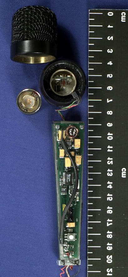
Click to zoom
Application Details
- Equipment Class
- TBF - Licensed Broadcast Transmitter Held to Face
- Date of Grant
- Jul 22, 2001
- Application Purpose
- Original Equipment
- Date of Application
- Jul 22, 2001
- Equipment Note
- Hand Held Radio Microphone
- Frequency Range
- 683.10000000 - 706.90000000
- Company
- Audio Limited
- Country
- United Kingdom
Documents & Files
Document Text
Text extracted from the exhibit documents filed with the FCC. Open a document above to read the original.
Users Manual
1 Operating Instructions HXiR Hand Held Radio Microphone Transmitter The HX iR is the latest innovative microprocessor controlled hand held transmitter from Audio Limited. The transmitter utilises inter-changeable, high quality condenser capsules from the Schoeps ™ Colette range, Thereby allowing a variety of applications where broadcast quality audio is required. The transmitter incorporates a microphone suspension specially designed by Rycote ™, for Audio Limited, to minimize the handling noise. The Hx iR can have up to 32 switchable frequencies over a 24MHz bandwidth. The transmitter antenna has been integrated into the design of the battery compartment to enhance the elegant appearance. The TX is powered from a single “AA” type 1.5 V battery, allowing the transmitter to be used for up to two and a half hours continuously from a good quality alkaline battery. A lithium “AA” type battery is available allowing seven hours continuous use. As with all previous products from Audio Limited, the transmitter has been designed for ease of use, with all user settable functions being controlled by the unique Switch iR. 2 Microphone Windshield 3 Microphone Capsule + Transmitter Body ON / Overload Indicator Microphone Windshield Identifier Infra-red Port ON Button Battery Compartment CoverAA Battery Compartment 4 Microphone Capsule Identification Ring Transmitter Body Infra red Port On Button On/Overload Indicator Battery Compartment Battery Cover 5 1) Battery Access The HX iR uses a single AA 1.5V (LR6, MN1500) type alkaline battery which is universally available. Grip the battery compartment cover and slide it away from the body of the HX iR to expose the battery compartment. Fit the AA battery with the Positive terminal uppermost and the negative terminal at the sprung end. Close the battery cover. Do not twist the cover. 2) Switching the transmitter ON Press and hold the grey “ON” button found below the infra red port, for one second. A red LED will illuminate the translucent ring above the battery compartment. There is no “OFF” switch on the transmitter preventing the transmitter from being turned off accidentally. The transmitter can only be turned off via the Switch iR, or by disconnecting the battery. To turn the transmitter off via the Switch iR [Subsequent or continuous pressing of the “ ON” switch will not have any effect on the transmitter function]: Press MENU followed by down arrow. Align the front of the Switch iR with the iR port on the transmitter and press OK OFF TX 3) Selecting the operating frequency The Switch iR enables the user to check, and change the frequency setting of the transmitter being addressed. To check frequency Step 1. Press MENU - display shows FREQUENCY Fr MHZ Align front of Switch iR with infra red port of TX Step 2 . Press OK - displays the set frequency of TX / RX e.g. 857.950 MHZ ( Pressing the OK button downloads the 32 frequencies from the unit into Switch iR ) 6 To Change Frequency i ) Follow Steps 1 & 2. ii ) Press OK- display will alternatively flash between frequency and channel number e.g. ''''857.95'''' ''''21'''' MHZCHANNEL iii ) Press up/ to scroll through any of the 32 frequencies down arrows pre-programmed into the receiver or transmitter until desired frequency is displayed iv ) Point the Switch iR - directly at the infra red port of the transmitter. v ) Press OK - to change the frequency. Display will show the new frequency of the transmitter. 4) Setting the Gain To Check gain setting: AF LEVEL i ) Press MENU followed- display will indicate: AF by the up arrow once TX Align front of Switch iR with infra red port of TX ii) Press OK - to view gain setting AF LEVEL on transmitter, e.g.: 8 TX To Change gain setting: i ) Follow the above steps 1 & 2 ii ) Press OK - the display will flash the ''''AF LEVEL'''' icon iii) Press up / down arrows - to select any one of ten gain settings once the desired gain setting is selected, Align front of Switch iR with infra red port of TX iv) Press OK - to set the new gain setting. Note: Steps between gain settings are approximately 3 to 4 dB. The “ON” indicator has a dual function. The translucent ring above the battery compartment is normally illuminated while the transmitter is switched on. This red light will turn off indicating an overload if the microphone experiences a loud signal. 7 The gain control should be adjusted to suit the application. Set the gain position such that the overload indicator remains illuminated during normal speech. The HxiR transmitter uses the same ultra low distortion, fast attack, fast decay overload compressor as found in the TX2020 pocket transmitter. In normal use, the gain should be set so that this compressor does not operate. Should an overload occur then the red LED will flash momentarily and the gain switch should be set lower. In the event that overloads occur, however, the only result will be compression rather than distortion. This means that if an interview is disturbed by unexpected aircraft or vehicles passing for example, an otherwise useless recording is rendered useable. The fast recovery of the compressor means that one does not have the problems of feedback associated with automatic gain controls in hand held radio microphone transmitters which are constantly varying their own gain. With the wide dynamic range of the system, however, it is always possible to set the gain control so that the compressor never operates. It is present only for the unexpected. 5) Setting the Low Frequency Cut Filter The LF cut filter gives approximately 10dB cut at 50Hz to reduce handling and wind n To Check status of low frequency filter: i ) Press MENU ii ) Press Up arrow twice - display will indicate LF Cut TX Align front of Switch iR with infra red port of TX iv) Press OK - to view the present status of the LF cut filter e.g.: On To Change the filter setting: i ) Follow the above steps ii ) Press OK - the display will flash ''''On'''' iii ) Press Up/down arrows - to toggle betwe…
Text truncated - open the document above for the full version.
Cover Letter(s)
Mr. David Fisher Cambridge Test and Measurement Limited St. Andrews Road Cambridge CB4 1ZJ 6 th July 2001 Dear Mr. Fisher, We would like to request that the circuit diagrams for the HXiR hand held transmitter, submitted for FCC type approval to part 74, be withheld from public inspection. The circuit diagrams that are held in the circuit diagrams folder, are commercially sensitive, and if they were available for public inspection it would result in substantial competitive harm. Our competitors widely acknowledge that the performance of Audio Limited’s wireless microphone systems, are among the best in the world, and therefore if they were able to freely obtain the information contained within the circuit diagrams folder it would greatly harm our share of the market. We have very tight controls to ensure that this information does not fall into the wrong hands. We would very much appreciate your assistance in this matter. Yours sincerely, Kishore Patel Managing Director.
External Photos
PHOTOGRAPHS OF EQUIPMENT Page No Microphone Front View, without battery cover2 Microphone Internal View with head assembly3 Power and processor PCB components4 RF and Audio PCB components5 RF and Audio PCB with Compander removed6 Microphone Front View, without battery cover Microphone Internal View with head assembly Power and processor PCB components RF and Audio PCB components RF and Audio PCB with Compander removed
ID Label/Location Info
30.0mm Font: Arial Bold Height 6mm Horizontal Scalin g 0.65 FCC ID NRK HXiR 7.5mm
Internal Photos
PHOTOGRAPHS OF EQUIPMENT Page No Microphone Front View, without battery cover2 Microphone Internal View with head assembly3 Power and processor PCB components4 RF and Audio PCB components5 RF and Audio PCB with Compander removed6 Microphone Front View, without battery cover Microphone Internal View with head assembly Power and processor PCB components RF and Audio PCB components RF and Audio PCB with Compander removed
Operational Description
3. Circuit Description. 1. Audio Stages. Audio circuitry is divided into three stages. 1). Input FET stage 2). Second stage 3). Final stage The Input FET stage is on PCB 691. Junction FET TR1 provides an input impedance greater than 1GΩ. The DC conditions of TR1 are set by RP1. The second stage is on PCB-698. TR6, TR7, TR8, TR9 and TR10 are CMOS switches used to control the gain of the operational amplifier IC1 by variation of the effective feed back resistor network. The light dependant resistor contained in the opto device OPTO shunts this network. The output from the IC1 is rectified and amplified in TR11 to control the LED current in device OPTO thus providing more than 20 dB of limited overload margin at full gain. The voltage at base of TR14 is increased via TR11 to switch off a ‘normally on’ LED ‘LED1’ which indicates the overload and the compression is taking place. Note that a wireless microphone is never used in this condition. The overload indication is to facilitate the setting of the gain to prevent such occurrence. The overload margin is thus primarily for type approval purposes and to prevent distortion in the event of unexpected high noises. IC3 is both a high pass and low pass filter. Frequencies below 30Hz and above 20KHz are attenuated. The low pass filter is used to reduce the occupied bandwidth for type approval purposes. IC3 provides a low impedance source required by the next stage. The final stage is on PCB 696. The main part of this stage is the frequency dependant square root companding system comprising IC7 and IC8. R87 and diode clippers D6 and D7 provide bandwidth limiting of overload transients which may be too short to be limited by second stage, thus ensuring the occupied bandwidth is limited even in the transient. Adjustment of deviation is provided by potentiometer RP3. 2. RF Stages. The RF Stages are on PCB 698. TR1 on this PCB is a low noise voltage controlled Colpitts oscillator tuned by varactors VC2 and VC3. VC3 provides the synthesiser locking to the required frequency at half the final output frequency and VC2 enables frequency modulation by audio frequencies from the 696 PCB via Connector 4. The second harmonic of the oscillator is selected in the tuned circuit in the drain of FET. Third and higher harmonics are attenuated by CT2/L4/C10 PI network. The tuned collector TR2 circuit amplifies the required frequency and the fundamental and higher harmonics are attenuated. Some signal from this amplifier is taken to the synthesiser FIN via C87/L6/CT8/C88 filter netw ork. The PI netw ork before the final collector tuned stage TR3 provides further attenuation to higher harmonics. The T-network followed by PI network after the TR3 stage ensures harmonics are satisfactorily reduced. Main tuning is accomplished by trimmer capacitors shown. Power adjustment requires adjustment of R12 and sometimes R15 to allow for variations in the gain of the RF devices. IC4 and IC5 form the synthesiser. A full description of the working of IC5 is available in the technical literature. X1 is the reference crystal to which the synthesiser is locked. The user via infrared interface provided selects one of the thirty-two frequencies on which the transmitter pre-programmed to operate. The unit is default to its last w orking frequency. During initial lock up conditions or after the frequency change has been requested, out of lock pulses from pin2 of IC5 is used to clamp the base of the output device TR3 via TR5 and TR4. Both DC bias and RF drive are removed thereby removing the output during the brief lock up phase. VCO is disabled in the event of wrong data being loaded. VC1 modulates the Reference crystal slightly by 1Hz sine wave (supplied by PIC micro-controller circuitry on PCB 697) via R26. The amplitude of this 1Hz signal once the initial set up done in the factory depends upon the battery voltage thus enables transmitting the battery status to the receiver. The tuned circuit L13 and C54 resonate to the crystal frequency. Its purpose is to step up RF voltage, which is then rectified in a voltage multiplying arrangement. This provides a zero current 50V supply for the condenser microphone capsule. A separate oscillator is not incorporated for this purpose in order to avoid additional unwanted spurious modulations of the RF carrier, thus ensuring the high quality of radiated signal. TR13 is used to eliminate the pulling of the reference frequency. 3. Power and Processor. PIC Micro controller and power supply circuits are on PCB 697. IC4, IC5, IC6 and IC7 form a step up DC-DC regulated –3V, +3V, and 7V supplies from 1.5V AA battery. IC1, IC2 and IC3 form the Micro controller circuitry with infrared interface. The table of thirty-two frequencies and other information such as Serial number are stored and accessed by IC1 in IC2. IC1 controls the correct data loading into the synthesiser (when the user via infrared interface requests frequency changes) and controls CMOS switches for Audio Gain adjustment and LF Cut select. It also outputs information such as unit’s battery voltage, serial number of the unit and notes w hich are pre- programmed in house to the remote infrared controller. In addition, it provides the facility of switching the IR communication off as a precaution against interference during the normal operation of the transmitter. HxiR is default to IR communication enabled.
Parts List/Tune Up Info
FD 1 C1 FD 1 C2 BOM FOR THE 704 BOARD.
Test Report
EQUIPMENT : MICROPHONE TYPE HXIRTEST REPORT NUMBER: CTMS 2001/1128a FCC Identifier : NRKHXIR CTMS FCC Registration Number : 93385 Page 1 of 32 TEST REPORT ON AUDIO LTD. Microphone Type HXIR FCC Authorization Procedures Part 2 subpart J and part 74 TEST REPORT NUMBER CTMS 2001/1128a March 2001 Prepared for: Audio Ltd. Audio House Progress Road High Wycombe Bucks. HP12 4JD England The results in this report refer to the tested unit only EQUIPMENT : MICROPHONE TYPE HXIRTEST REPORT NUMBER: CTMS 2001/1128a FCC Identifier : NRKHXIR CTMS FCC Registration Number : 93385 Page 2 of 32 Certificate of Application Cambridge Test and Measurement Services Ltd., certifies that the product tested was fully compliant with the requirements of Parts 2 & 74 of the FCC Code of Regulations 47CFR, the results of which are contained in this test report No: CTMS 2001/1128a I certify that the application was prepared under my supervision and that to the best of my knowledge and belief, the facts set forth in this application and technical data, are true and correct. Signature : Date: Name: David Fisher Title: Radio Technical Manager EQUIPMENT : MICROPHONE TYPE HXIRTEST REPORT NUMBER: CTMS 2001/1128a FCC Identifier : NRKHXIR CTMS FCC Registration Number : 93385 Page 3 of 32 General Test Information Date Test Sample Received:20 th March 2001 Date Testing Started:20 th March 2001 Date Testing Finished:27 th March 2001 Equipment Serial Number:13160-05 CTMS Project Number :2001/1128a Test Engineer:K. D. Barker Report Copy No 1 EQUIPMENT : MICROPHONE TYPE HXIRTEST REPORT NUMBER: CTMS 2001/1128a FCC Identifier : NRKHXIR CTMS FCC Registration Number : 93385 Page 4 of 32 TABLE OF CONTENTS PartPAGE No 2.1033Application for Certification 5 2.1046RF Power Output at terminals 6 2.1047 (a)Modulation Characteristics 7 2.1047 (b)Modulation limiting characteristic 9 2.1049 (1)Occupied Bandwidth11 2.1051Spurious emissions at antenna terminals13 2.1055 (a)(1)(d)(2)Frequency Stability 16 2.1057Frequency spectrum to be investigated17 General Information and Attachments : 18 Equipment Under Test 18 Photographs of Equipment.19 Company Accreditations & Credentials25 EQUIPMENT : MICROPHONE TYPE HXIRTEST REPORT NUMBER: CTMS 2001/1128a FCC Identifier : NRKHXIR CTMS FCC Registration Number : 93385 Page 5 of 32 2.1033 Application for Certification For use in accordance with FCC Rules and Regulations 47 CFR parts 2 and parts 74. 2.1033 (c) (1)Name of applicant : Audio Ltd. Address of applicant:Audio House, Progress Road, High Wycombe, Bucks. HP12 4JD Contact:Mr. Kishore Patel 2.1033 (c) (2)FCC Identifier:NRKHXIR Model Type Number:HXIR 2.1033 (c) (3)Installation and operating instructions :See attachments. 2.1033 (c) (4)Type(s) of emission:Frequency Modulated 200KF3E 2.1033 (c) (5)Frequency range:683.10 - 706.90 MHz 2.1033 (c) (6)Output power range:10 mW 2.1033 (c) (7)Maximum power rating (part 74):250 mW 2.1033 (c) (8)dc voltage applied to power amplifier:3.0 V dc current to power amplifier: N/A 2.1033 (c) (9)Tune-up procedure for RF power: See attachments. 2.1033 (c) (10)Schematic and description of circuit:See attachments. 2.1033 (c) (11)Photograph of identification plate / label:See attachments. 2.1033 (c) (12)Photographs of equipment:See page 19 2.1033 (c) (14) Measurement data:This report EQUIPMENT : MICROPHONE TYPE HXIRTEST REPORT NUMBER: CTMS 2001/1128a FCC Identifier : NRKHXIR CTMS FCC Registration Number : 93385 Page 6 of 32 47 CFR Part 2.1033 (c) (14) MEASUREMENT DATA. RF Power Output at terminals - 47 CFR 2.1046 The transmitter is operated under standard test conditions, using the standard test voltage from a single AA internal battery. The transmitter is fitted with a temporary 50 ohm antenna socket to allow conducted measurements to be made. The transmitter, tuned by the manufacturer in accordance with the stated procedure, was keyed in an unmodulated condition and the output was connected to a RF Power Meter via a matching Power Sensor. The RF Power Output was observed and recorded. The RF Power Output was measured in accordance with the following test configuration, using the test instruments listed, on the lower, mid and upper frequencies of the switching range. (Calibrated items are indicated in Blue) EUT Power Sensor Power Meter Ambient Conditions.Temperature = 25ºCRelative Humidity = 24 % Test instruments used : RF Power Meter :Hewlett Packard Type HP 435B, S/N 2005A03070. RF Power Sensor :Hewlett Packard Type HP 8481B, S/N 1801A01640 Results in accordance with Part 2.1046 and 74.861. e.(1) Unmodulated Power TRANSMITTER POWER (mWatts) 683.10 MHz 695.00 MHz706.90 MHz 9.8 mW6.32 mW3.8 mW LIMIT in 74.861 (e) (1) (ii)250 mW EQUIPMENT : MICROPHONE TYPE HXIRTEST REPORT NUMBER: CTMS 2001/1128a FCC Identifier : NRKHXIR CTMS FCC Registration Number : 93385 Page 7 of 32 Modulation Characteristics - 47 CFR 2.1047 (a) The transmitter is operated under standard test conditions and the output monitored with a modulation analyzer of normal impedance matching that of the transmitter. A test signal of 1000Hz sine wave is applied to the normal input of the modulation circuit via a dummy capsule to the audio processing circuits, the level adjusted to give ±20kHz deviation. Ensuring the audio input level is maintained constant, the modulation frequency is varied from 50Hz to 25,000Hz. The variation in the depth of modulation is observed and recorded. The modulation characteristic was measured in accordance with the following test configuration, using the test instruments listed. (Calibrated items are indicated in Blue) EUT Modulation Analyzer Audio Analyzer AC Generator Voltmeter Ambient Conditions.Temperature = 25ºCRelative Humidity = 24 % Test instruments used : Audio Analyzer : Hewlett Packard Audio Analyzer Type HP 8903B, S/N2836A05420 Modulation Analyzer: Hewlett Packard Mod Analyzer Type HP 8901B, S/N2642A01009 EQUIPMENT : MICROPHONE TYPE HXIRTEST REPORT NUMBER: CTMS 2001/1128a FCC Identifier : NRKHXIR CTMS FCC Registration Number : 93385…
Text truncated - open the document above for the full version.
Contact Information
Applicant
Lee Stone
Test Firm
Cambridge Test & Measurement ServicesJon Larkin
Technical Specifications
| # | Rule Parts | Frequency Range | Power Output | Emission | Tolerance |
|---|---|---|---|---|---|
| 1 | 74.861 | 683.1 MHz - 706.9 MHz | 10.00 mW | 200KF3E | 10000.0000000000 Hz |
Other Applications from Audio Limited
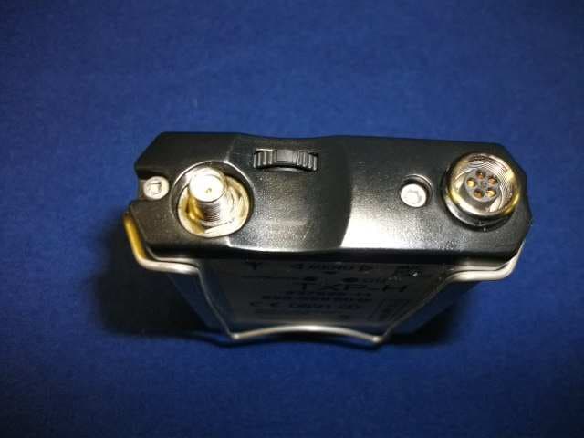
NRKTXP
Dec 18, 2014Professional Body-Worn Wireless Microphone Transmitter
Equipment Class
TBT - Licensed Broadcast Transmitter Worn on Body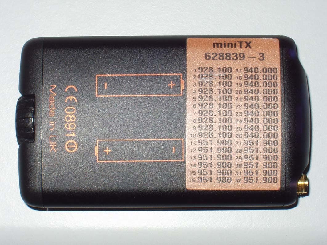
NRKMINITX
Sep 21, 2007MINITX Wireless Microphone Transmitter
Equipment Class
TNT - Licensed Non-Broadcast Transmitter Worn on Body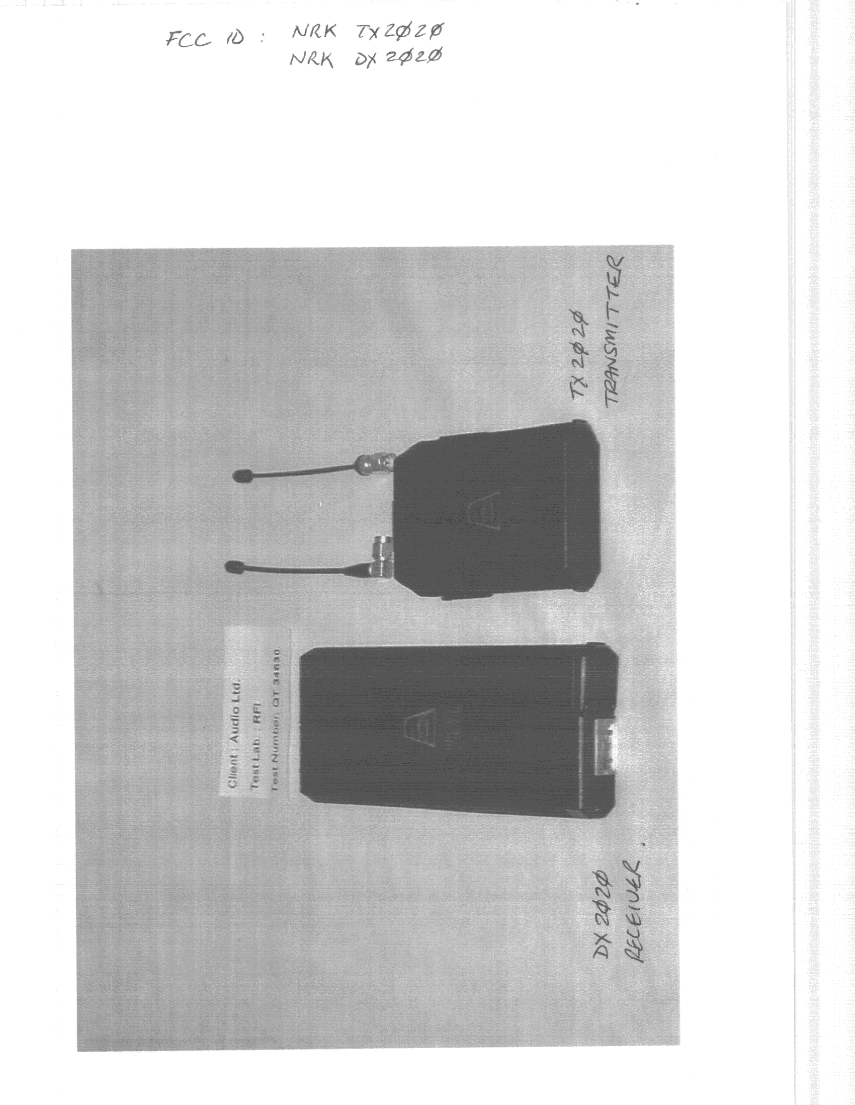
NRKTX2020
Sep 09, 1998TBT - Licensed Broadcast Transmitter Worn on Body
Equipment Class
TBT - Licensed Broadcast Transmitter Worn on Body