Text extracted from the exhibit documents filed with the FCC. Open a document above to read the original.
FCC ID: NSK0016A SECTION 6 USER'S MANUAL FCC ID: NSK0016A FCC ID: NSK0016A Regulatory Interference information Some telephone equipment generates, uses, and can radiate radio frequency energy, and if not installed and used properly, may cause interference to radio or TV reception. This equipment has been tested and found to comply with the limits for a Class B digital device, pursuant to Part 15 of the FCC Rules. These limits are designed to provide reasonable protection against harmful interference in a residential installation. This equipment generates, uses, and can radiate radio frequency energy, and if not installed and used in accordance with the instructions, may cause harmful interference to radio communications. However, there is no guarantee that interference will not occur in a particular installation. If this equipment does cause harmful interference to radio or television reception, which can be determined by turning the equipment off and on, the user is encouraged to try to correct the interference by one or more of the following measures. • Reorient or relocate the receiving antenna. • Increase the separation between the equipment and receiver. • Connect the equipment to an outlet on a circuit different from that to which the receiver is connected. • Consult the dealer or an experienced radio/TV technician for help. This device complies with Part 15 of the FCC Rules. Operation is subject to the following two conditions: 1. This device may not cause harmful interference. 2. This device must accept any interference received, including interference that may cause undesired operation. Note: Privacy of communications may not be ensured when using this phone.
TransPort User Guide TM © 2000 Home Wireless Networks, Inc. All rights reserved. AirWay™ TransPort User Guide Part Number 84-xxxx-000 A0600 Home Wireless Networks, Inc. 3145 Avalon Ridge Place, Suite 200 Norcross, Georgia 30071-1582 The information in this manual is subject to change without notice and should not be construed as a commitment by Home Wireless Networks. Home Wireless Networks assumes no responsibility or liability for any errors or inaccuracies that may appear in this document. The contents of this manual are the property of Home Wireless Networks, Inc. and are copyrighted. Any reproduction in whole or in part is strictly prohibited. AirWay is a trademark of Home Wireless Networks, Inc. Windows ® is a registered trademark of Microsoft ® Corporation. Contents• 3 Contents Getting Started . . . . . . . . . . . . . . . . . . . . . . . . . . . . . . . . . . . . . . . . . . . 4 About AirWay TransPort. . . . . . . . . . . . . . . . . . . . . . . . . . . . . . . . . . 4 Before You Begin . . . . . . . . . . . . . . . . . . . . . . . . . . . . . . . . . . . . . . . 5 Requirements . . . . . . . . . . . . . . . . . . . . . . . . . . . . . . . . . . . . . . . . . 5 Checking Parts. . . . . . . . . . . . . . . . . . . . . . . . . . . . . . . . . . . . . . . . 5 Choosing a Location . . . . . . . . . . . . . . . . . . . . . . . . . . . . . . . . . . . 5 Safety Instructions . . . . . . . . . . . . . . . . . . . . . . . . . . . . . . . . . . . . . . . 6 Use with medical devices . . . . . . . . . . . . . . . . . . . . . . . . . . . . . . . 7 Battery cautions . . . . . . . . . . . . . . . . . . . . . . . . . . . . . . . . . . . . . . . 8 Preventing static electricity damage . . . . . . . . . . . . . . . . . . . . . . . 8 Installing TransPort. . . . . . . . . . . . . . . . . . . . . . . . . . . . . . . . . . . . . . . 9 Adding Computers To The Network . . . . . . . . . . . . . . . . . . . . . . . . 11 Installing Network Cards . . . . . . . . . . . . . . . . . . . . . . . . . . . . . . . . . 11 Installing a PCI card . . . . . . . . . . . . . . . . . . . . . . . . . . . . . . . . . . 11 Installing a PCMCIA Card . . . . . . . . . . . . . . . . . . . . . . . . . . . . . 12 Installing the TransPort drivers and software . . . . . . . . . . . . . . . . . 12 Managing Your TransPort Network . . . . . . . . . . . . . . . . . . . . . . . . 14 Regulatory Statements. . . . . . . . . . . . . . . . . . . . . . . . . . . . . . . . . . . . 16 United States . . . . . . . . . . . . . . . . . . . . . . . . . . . . . . . . . . . . . . . . . . 16 Canada . . . . . . . . . . . . . . . . . . . . . . . . . . . . . . . . . . . . . . . . . . . . . . . 19 4 Getting Started About AirWay TransPort AirWay TransPort is a high-speed 802.11 wireless networking product that allows you to: nBuild a fast, flexible, secure Wireless Local Area Network (WLAN) in your home or small business. nConnect WLAN clients to an existing wired (Ethernet-based) LAN. nEasily add new computers to the network or move existing computers around without the hassle and expense of running new cables between the computers and a network hub. 5 Before You Begin Requirements Each computer in your TransPort network must have the following: nMicrosoft Windows 95/98 nAn AirWay PCMCIA or PCI card nA CD-ROM drive Checking Parts Your AirWay TransPort package contains the following items: nAirWay TransPort (1) nPower Supply Adapter (1) n9’ Ethernet RJ-45 Cable (1) nSheet of self-adhesive protective feet nAirWay TransPort CD-ROM •Configuration Software •Online User Guide nPrinted User Documentation If any parts are missing or broken, contact your equipment supplier. Choosing a Location Remember the following points when deciding where to place TransPort. nTransPort must be located within 6 feet of an electrical outlet that is not controlled by a wall switch. If connecting to a wired Ethernet LAN, you must also place TransPort within 9 feet of a Ethernet jack. nIn general, all computers in your WLAN must be within 100 - 300 feet of TransPort. Although radio waves pass quite readily through most walls as well as glass, they will not pass through metal. If your walls or floors contain metal, or there are metal 6 structures between TransPort and network computers, you will noticed degraded service. nPer FCC guidelines on radio frequency radiation exposure, this product should not be installed within 20 cm (7.8 iuches) of the user or other nearby individuals. nDo not install TransPort in the following locations: •Attics, garages, or other temperature-extreme locations •On top of or immediately adjacent to a TV, VCR, stereo system, or computer, or beside a window facing a street with heavy traffic. •Near radiators or microwave ovens, or in direct sunlight. •Where it might be subject to water splash, dust, or mechanical vibration. Safety Instructions When using your telephone equipment, basic safety precautions should always be followed to reduce the risk of fire, electric shock, and injury. 1.Read and understand all instructions. 2.Follow all warnings and instructions marked on the product. 3.Do not use this product near water or when you are wet (for example, near a bath tub, kitchen sink, laundry tub, wash bowl, wet basement, or swimming pool). Unplug this product from the wall outlet before cleaning. Do not use liquid cleaners or aerosol cleaners. Use a damp cloth for cleaning. Do not plug the product back in until it is thoroughly dry. 4.Avoid using a telephone (other than a cordless one) during an electrical storm. There may be a remote risk of electric shock. 5.Do not use a telephone in the vicinity of a gas leak. If you suspect a gas leak, report it immediately using a telephone located away from the area where the gas is leaking. Also make sure the Controller unit is located away from the area of the suspected leak. 7 6.This product should be operated only from the type of power source indicated on the marking label. If you are not sure of the type of power that i…
Text truncated - open the document above for the full version.
FCC ID: NSK0016A FCC ID: NSK0016A
April 11, 2001 Joe Dichoso Federal Communications Commission Equipment Authorization Division 7435 Oakland Mills Road Columbia, MD 21046 Dear Mr. Dichoso, You have requested information regarding Home Wireless Networks submittal for FCC ID: NSK0016A. After the application was submitted, Home Wireless Networks returned with the same model except that it had been modified to produce higher output power. They had a few minor changes to the digital device circuitry that should only have affected the power line conducted emissions. Only the transmitter tests have been provided in the certification application to the FCC since the digital device was tested and approved under a separate DoC report. The addendum report contains a majority of the data for the final model except for tests that were considered duplicative and are only found in the original report. Therefore the following portions of the original report digital device radiated emissions should still be referenced in order to review all necessary required information. 1.2 Related Submittal(s)/Grant(s) 2.6 Antenna Description 2.13 Processing Gain Additionally all the original internal photographs submitted are accurate, except for 4 which are included in the back of the addendum report. I hope that you find that this information fulfills the necessary FCC requirements for the Part 15 Certification requirements. If you have any questions, please feel free to contact me at (770)741- 0717. Sincerely, Timothy R. Johnson
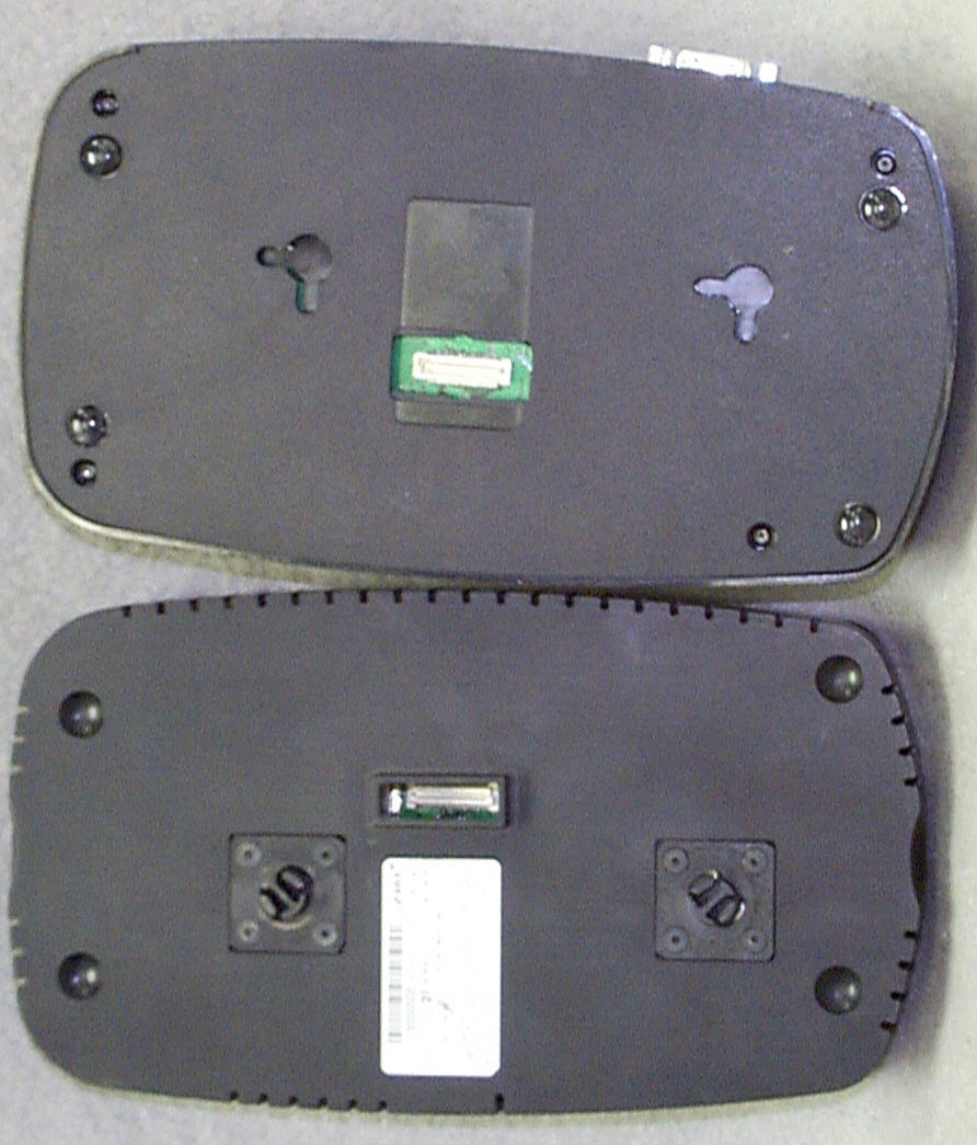
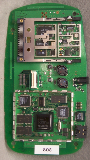
FCC ID: NSK0016A SECTION 5 PHOTOGRAPHS FCC ID: NSK0016A PHOTOS OF THE TESTED EUT The following photos are attached: Photo 1.Front View of EUT as Tested with NCU Photo 2.Rear View of EUT as Tested with NCU Photo 3.Side View of EUT as Tested with NCU, Showing Proper Connection of AC Power Photo 4.EUT (On Right), Separated from NCU Photo 5.EUT, Top View of Board Photo 6.EUT, Top View of Board with Shields Removed Photo 7.EUT, Bottom View of Board Photo 8.EUT, Bottom View of Board with Shields Removed Photo 9.Top of Connector Board Photo 10. Bottom of Connector Board Photo 11.Front View of EUT as a Stand Alone Product Photo 12.Rear View of EUT as a Stand Alone Product Photo 13.Side View of EUT as a Stand Alone Product, Showing Proper Connection of AC Power Photo 14.Top View of EUT as a Stand Alone Product, Top Cover Removed Photo 15.Top View of EUT as a Stand Alone Product, Secondary Cover Removed FCC ID: NSK0016A Photo 1. Front View of EUT as Tested with NCU FCC ID: NSK0016A Photo 2. Rear View of EUT as Tested with NCU FCC ID: NSK0016A Photo 3. Side View of EUT as Tested with NCU, Showing Proper Connection of AC Power FCC ID: NSK0016A Photo 4. EUT (On Right), Separated from NCU FCC ID: NSK0016A Photo 5. EUT, Top View of Board FCC ID: NSK0016A Photo 6. EUT, Top View of Board with Shields Removed FCC ID: NSK0016A Photo 7. EUT, Bottom View of Board FCC ID: NSK0016A Photo 8. EUT, Bottom View of Board with Shields Removed FCC ID: NSK0016A Photo 9. Top of Connector Board FCC ID: NSK0016A Photo 10. Bottom of Connector Board FCC ID: NSK0016A Photo 11. Front View of EUT as a Stand Alone Product FCC ID: NSK0016A Photo 12. Rear View of EUT as a Stand Alone Product FCC ID: NSK0016A Photo 13. Side View of EUT as a Stand Alone Product, Showing Proper Connection of AC Power FCC ID: NSK0016A Photo 14.Top View of EUT as a Stand Alone Product, Top Cover Removed FCC ID: NSK0016A Photo 15.Top View of EUT as a Stand Alone Product, Secondary Cover Removed
FCC ID: NSK0016A SECTION 3 LABELING INFORMATION FCC ID: NSK0016A FCC ID: NSK0016A
Photo 5. EUT, Top View of Board Antenna
Home Wireless Networks, Inc. FCC Part 15, Certification Application 95-0016-XXX November 24, 1999 MEASUREMENT/TECHNICAL REPORT COMPANY NAME:Home Wireless Networks, Inc. MODEL:95-0016-XXX FCC ID:NSK0016A DATE:November 24, 1999 This report concerns (check one): Original grant X Class II change_____ Equipment type: Deferred grant requested per 47 CFR 0.457(d)(1)(ii)? yes_____ No X If yes, defer until:_________________ date N.A. agrees to notify the Commission by N.A. date of the intended date of announcement of the product so that the grant can be issued on that date. Report prepared by: United States Technologies, Inc. 3505 Francis Circle Alpharetta, GA 30004 Phone Number: (770) 740-0717 Fax Number: (770) 740-1508 FCC ID: NSK0016A TABLE OF CONTENTS AGENCY AGREEMENT LETTER OF CONFIDENTIALITY SECTION 1 GENERAL INFORMATION 1.1Product Description 1.2Related Submittal(s) SECTION 2 TESTS AND MEASUREMENTS 2.1Configuration of Tested EUT 2.2Test Facility 2.3Test Equipment 2.4Modifications 2.5Test Procedure and Results 2.6Antenna Description 2.7Peak Power (Antenna Conducted at Antenna Terminal) 2.8Antenna Conducted Spurious Emissions 2.9Peak Radiated Spurious Emissions 2.10Average Radiated Spurious Emissions 2.11Minimum 6 dB Bandwidth 2.12Power Spectral Density 2.13Processing Gain 2.14Power Line Conducted Emissions for Transmitter SECTION 3 LABELING INFORMATION SECTION 4 BLOCK DIAGRAM(S)/ SCHEMATIC(S) SECTION 5 PHOTOGRAPHS SECTION 6 USER'S MANUAL FCC ID: NSK0016A LIST OF FIGURES AND TABLES FIGURES 1)Test Configuration 2) Photograph(s) for Spurious, Fundamental, and Conducted Emissions 3) Peak Power Output 4) Antenna Conducted Spurious Emissions 5) Peak Radiated Spurious Emissions 6) Average Radiated Spurious Emissions 7) 6 dB Bandwidth 8) Power Spectral Density TABLES 1)EUT and Peripherals 2) Test Instruments 3) Peak Power Output 4) Peak Radiated Spurious Emissions 5) Average Radiated Spurious Emissions 6) 6 dB Bandwidth 7) Power Spectral Density 8) Conducted Emissions Data FCC ID: NSK0016A SECTION 1 GENERAL INFORMATION FCC ID: NSK0016A GENERAL INFORMATION 1.1Product Description The Equipment Under Test (EUT) is a Home Wireless Networks, Inc., Model 95-0016-XXX. The Model 95-0016-XXX is an IEEE 802.11 Wireless Ethernet Transceiver Module (2.4 GHz) which may be used as either a self contained unit or attached to Home Wireless Networks, Inc. NCU controller (model 95-0005-XXX) for added functionality and communication with other Home Wireless Networks, Inc. products. When utilized as a self contained unit, the EUT obtains power through use of an external AC adapter. Units used with a NCU controller are connected directly to the bottom side of the NCU and obtain their power from the NCU through the interface connecting the two units. The following is a list of the channels designed into the EUT: RF Frequencies HWN IEEE 802.11 Wireless Ethernet Module RF CHANNEL TRANSMIT/RECEIVE FREQUENCY (MHZ) RF LOCAL OSCILLATOR FREQUENCY (Internal radio version only) 124122038 224172043 324222048 424272053 524322058 624372063 724422068 824472073 924522078 1024572083 1124622088 FCC ID: NSK0016A 1.2Related Submittal(s)/Grant(s) The EUT will be used with part of a system to send/receive data. The transceiver presented in this report will be used with other like transceivers. The EUT may also be used along with a Home Wireless Networks, Inc. Model 95-0005-XXX which has been previously submitted and approved under FCC ID: NSK0005A. The EUT is subject to the following authorizations: a) Certification as a transmitter b) Certification or DoC as a computer peripheral device b)Verification as a receiver and digital device The information contained in this report is presented for the certification portion of the EUT. A separate report (UST # 99-865) has been issued which covers the requirements for the DoC & verification authorization(s) for the EUT. FCC ID: NSK0016A SECTION 2 TESTS AND MEASUREMENTS FCC ID: NSK0016A TEST AND MEASUREMENTS 2.1 Configuration of Tested System The sample was tested per ANSI C63.4, Methods of Measurement from Low-Voltage Electrical and Electronic Equipment in the Range of 9 kHz to 40 GHz (1992). Conducted and radiated emissions data were taken with the test receiver or spectrum analyzer's resolution bandwidth adjusted to 9 kHz and 120 kHz, respectively. All measurements are peak unless stated otherwise. The video filter associated with the spectrum analyzer was off throughout the evaluation process. Interconnecting cables were manipulated as necessary to maximize emissions. Interconnecting cables were manipulated as necessary to maximize emissions. A block diagram of the tested system is shown in Figure 1. Test configuration photographs for spurious and fundamental emissions are shown in Figure 2. The EUT is internally identical for both versions (self contained versus for use with NCU). The unit that connects to a NCU controller was selected for testing since it consists of additional electrical devices connected to the EUT. Since AC power is supplied either directly to the unit in a self contained configuration, or through the NCU when used in it is connected to the EUT, two separate conducted emissions tests were performed. The sample used for testing was received by U.S. Technologies on November 2, 1999 in good condition. 2.2 Test Facility Testing was performed at US Tech's measurement facility at 3505 Francis Circle, Alpharetta, GA. This site has been fully described and submitted to the FCC, and accepted in their letter marked 31040/SIT. Additionally this site has also been fully described and submitted to Industry Canada (IC), and has been approved under file number IC2982. 2.3 Test Equipment Table 2 describes test equipment used to evaluate this product. 2.4 Modifications No modifications were made by US Tech, to bring the EUT into compliance with FCC Part 15 limits for the transmitter portion of the EUT. FCC ID: NSK0005A FIGURE 1a TEST CONFIGURATION Configuration for Radiated and Conducted T…
Text truncated - open the document above for the full version.
FCC ID: NSK0016A 2.6 Antenna Description (Paragraph 15.203) An intentional radiator shall be designed to ensure that no antenna other than that furnished by the responsible party shall be used with the device. The use of a permanently attached antenna or of an antenna that uses a unique coupling to the intentional radiator shall be considered sufficient to comply with the provisions of this section. The Model Home Wireless Networks, Inc. 95-0016-XXX incorporates an internal antenna only. FCC ID: NSK0016A 2.7 Peak power within the band 2.4 – 2.4835 GHz per FCC Section 15.247(b) Peak power within the band 2.4–2.4835 GHz has been measured with a spectrum analyzer by connecting the spectrum analyzer directly via a short cable to the antenna output terminals or across the antenna leads on the PCB as specified by the manufacturer. The spectrum analyzer was set for a 50 Ω impedance with the VBW > RBW 6 dB bandwidth. The results of the measurements are given in Table 3 and Figure 3a through Figure 3c. The spectrum analyzer did not have a RBW greater than the 6 dB bandwidth for the largest fundamental bandwidth, therefore this data was taken using the channel power function of the spectrum analyzer. The EUT did not incorporate any antennas of directional gain greater than 6 dBi, therefore the output power has not been reduced as required by 15.247(b)(3). FCC ID: NSK0016A TABLE 3 PEAK POWER OUTPUT Test Date:November 2 & 3, 1999 UST Project:99-867 Customer:Home Wireless Networks, Inc. Model:95-0016-XXX Frequency of Fundamental (GHz) Measurement (dBm)* Measurement (Watt)* FCC Limit (Watt) 2.41215.00.03161.0 2.43714.00.02511.0 2.46211.80.01511.0 * Measurement includes 0.4 dB cable loss Test Results Reviewed By Signature: Name: Tim R. Johnson FCC ID: NSK0016A Figure 3a. Peak Power per FCC Section 15.247(b) (Low) FCC ID: NSK0016A Figure 3b. Peak Power per FCC Section 15.247(b) (Mid) FCC ID: NSK0016A Figure 3c. Peak Power per FCC Section 15.247( b) (High) FCC ID: NSK0016A 2.8 Antenna Conducted Spurious Emission in the Frequency Range 30 - 25000 MHz (FCC Section 15.247(c)) Antenna conducted spurious emissions in the frequency range 30-25000 MHz have been measured with a spectrum analyzer by connecting the spectrum analyzer directly via a short cable to the antenna output terminals or across the antenna leads on the PCB as specified by the manufacturer. The spectrum analyzer was set for a 50 Ω impedance with the RBW = 100 kHz & VBW > RBW. All spurious emissions were measured to be greater than 20 dB down from the fundamental. The results of conducted spurious emissions are given in Figure 4a through Figure 4l. FCC ID: NSK0016A Figure 4a Antenna Conducted Spurious Emissions 15.247(c) Low FCC ID: NSK0016A Figure 4b Antenna Conducted Spurious Emissions 5.247(c) Low FCC ID: NSK0016A Figure 4c Antenna Conducted Spurious Emissions 15.247(c) Low FCC ID: NSK0016A Figure 4d Antenna Conducted Spurious Emissions 15.247(c) Low FCC ID: NSK0016A Figure 4e Antenna Conducted Spurious Emissions 15.247(c) Mid FCC ID: NSK0016A Figure 4f Antenna Conducted Spurious Emissions 15.247(c) Mid FCC ID: NSK0016A Figure 4g Antenna Conducted Spurious Emissions 15.247(c) Mid FCC ID: NSK0016A Figure 4h Antenna Conducted Spurious Emissions 15.247(c) Mid FCC ID: NSK0016A Figure 4i Antenna Conducted Spurious Emissions 15.247(c) High FCC ID: NSK0016A Figure 4j Antenna Conducted Spurious Emissions 15.247(c) High FCC ID: NSK0016A Figure 4k Antenna Conducted Spurious Emissions 15.247(c) High FCC ID: NSK0016A Figure 4l Antenna Conducted Spurious Emissions 15.247(c) High
FCC ID: NSK0016A 2.9 Peak Radiated Spurious Emission in the Frequency Range 30 - 25000 MHz (FCC Section 15.247(c)) A preliminary scan was performed on the EUT to determine frequencies that were caused by the transmitter portion of the product. Significant emissions that fell within restricted bands were then measured on an OAT’s site. Radiated measurements below 1 GHz were tested with a RBW = 120 kHz. Radiated measurements above 1 GHz were measured using a RBW = VBW = 1 MHz. The results of peak radiated spurious emissions falling within restricted bands are given in Table 4a (low), Table 4b, (mid), Table 4c (high) and Figure 5a-5b (low), Figure 5c-5f (mid) and Table 5g-5j (high). FCC ID: NSK0016A Figure 5a Peak Radiated Spurious Emission 15.247(c) Low FCC ID: NSK0016A Figure 5b Peak Radiated Spurious Emission 15.247(c) Low FCC ID: NSK0016A Figure 5c Peak Radiated Spurious Emission 15.247(c) Mid FCC ID: NSK0016A Figure 5d Peak Radiated Spurious Emission 15.247(c) Mid FCC ID: NSK0016A Figure 5e Peak Radiated Spurious Emission 15.247(c) Mid FCC ID: NSK0016A Figure 5f Peak Radiated Spurious Emission 15.247(c) Mid FCC ID: NSK0016A Figure 5g Peak Radiated Spurious Emission 15.247(c) High FCC ID: NSK0016A Figure 5h Peak Radiated Spurious Emission 15.247(c) High FCC ID: NSK0016A Figure 5i Peak Radiated Spurious Emission 15.247(c) High FCC ID: NSK0016A Figure 5j Peak Radiated Spurious Emission 15.247(c) High FCC ID: NSK0016A TABLE 4a PEAK RADIATED SPURIOUS EMISSIONS (Low) Test Date:November 2 & 3, 1999 UST Project:99-867 Customer:Home Wireless Networks, Inc. Model:95-0016-XXX Freq. (GHz) Test Data (dBm) @3m High Pass Filter Loss (dB) Amp. Gain (dB) Antenna Factor (dB) Cable Loss (dB) Results (uV/m) @3m FCC Limits (uV/m) @3m 2.786-61.21.634.931.44.2254.35000 4.824-67.4**1.034.234.77.9283.55000 ** = Instrumentation ground floor SAMPLE CALCULATION: RESULTS (uV/m @ 3m) = Antilog ((-61.2 + 1.6 - 34.9 + 31.4 + 4.2 + 107)/20) = 254.3 CONVERSION FROM dBm TO dBuV = 107 dB Tester Signature: Name: Tim R. Johnson FCC ID: NSK0016A TABLE 4b PEAK RADIATED SPURIOUS EMISSIONS (Mid) Test Date:November 2 & 3, 1999 UST Project:99-867 Customer:Home Wireless Networks, Inc. Model:95-0016-XXX Freq. (GHz) Test Data (dBm) @3m High Pass Filter Loss (dB) Amp. Gain (dB) Antenna Factor (dB) Cable Loss (dB) Results (uV/m) @3m FCC Limits (uV/m) @3m 1.688-55.91.935.127.83.2278.65000 2.063-58.51.434.829.63.7261.05000 2.811-61.41.634.931.44.2250.25000 4.874-67.3**1.034.134.88.1295.85000 ** = Instrumentation ground floor SAMPLE CALCULATION: RESULTS (uV/m @ 3m) = Antilog ((-55.9 + 1.9 - 35.1 + 27.8 + 3.2 + 107)/20) = 278.6 CONVERSION FROM dBm TO dBuV = 107 dB Tester Signature: Name: Tim R. Johnson FCC ID: NSK0016A TABLE 4c PEAK RADIATED SPURIOUS EMISSIONS (High) Test Date:November 2 & 3, 1999 UST Project:99-867 Customer:Home Wireless Networks, Inc. Model:95-0016-XXX Freq. (GHz) Test Data (dBm) @3m High Pass Filter Loss (dB) Amp. Gain (dB) Antenna Factor (dB) Cable Loss (dB) Results (uV/m) @3m FCC Limits (uV/m) @3m 1.717-53.41.735.128.03.2372.45000 2.093-60.51.434.829.73.7210.05000 2.840-61.91.634.931.44.3238.15000 4.934-67.8**1.034.134.98.2289.75000 ** = Instrumentation ground floor SAMPLE CALCULATION: RESULTS (uV/m @ 3m) = Antilog ((-53.4 + 1.7 - 35.1 + 28.0 + 3.2 + 107)/20) = 372.4 CONVERSION FROM dBm TO dBuV = 107 dB Tester Signature: Name: Tim R. Johnson FCC ID: NSK0016A 2.10 Average Spurious Emission in the Frequency Range 30 - 25000 MHz (FCC Section 15.247(c)) The EUT is capable of transmitting in excess of 100 msec periods, therefore duty cycle corrections were considered not applicable. Additionally, the peak measurements met with the average limits. The results of average radiated spurious emissions falling within restricted bands are given in Table 5a (low), Table 5b, (mid), Table 5c (high) and Figure 6. FCC ID: NSK0016A Figure 6 Average Radiated Spurious Emission 15.247(c) Since the EUT can transmit for longer than 100 msec duration (100% duty cycle) and the peak measurements met with the average limits, further testing was deemed unnecessary. FCC ID: NSK0016A TABLE 5a PEAK RADIATED SPURIOUS EMISSIONS (Low) Test Date:November 2 & 3, 1999 UST Project:99-867 Customer:Home Wireless Networks, Inc. Model:95-0016-XXX Freq. (GHz) Test Data (dBm) @3m High Pass Filter Loss (dB) Amp. Gain (dB) Antenna Factor (dB) Cable Loss (dB) Results (uV/m) @3m FCC Limits (uV/m) @3m 2.786-61.21.634.931.44.2254.3500 4.824-67.4**1.034.234.77.9283.5500 ** = Instrumentation ground floor SAMPLE CALCULATION: RESULTS (uV/m @ 3m) = Antilog ((-61.2 + 1.6 - 34.9 + 31.4 + 4.2 + 107)/20) = 254.3 CONVERSION FROM dBm TO dBuV = 107 dB Tester Signature: Name: Tim R. Johnson FCC ID: NSK0016A TABLE 5b PEAK RADIATED SPURIOUS EMISSIONS (Mid) Test Date:November 2 & 3, 1999 UST Project:99-867 Customer:Home Wireless Networks, Inc. Model:95-0016-XXX Freq. (GHz) Test Data (dBm) @3m High Pass Filter Loss (dB) Amp. Gain (dB) Antenna Factor (dB) Cable Loss (dB) Results (uV/m) @3m FCC Limits (uV/m) @3m 1.688-55.91.935.127.83.2278.6500 2.063-58.51.434.829.63.7261.0500 2.811-61.41.634.931.44.2250.2500 4.874-67.3**1.034.134.88.1295.8500 ** = Instrumentation ground floor SAMPLE CALCULATION: RESULTS (uV/m @ 3m) = Antilog ((-55.9 + 1.9 - 35.1 + 27.8 + 3.2 + 107)/20) = 278.6 CONVERSION FROM dBm TO dBuV = 107 dB Tester Signature: Name: Tim R. Johnson FCC ID: NSK0016A TABLE 5c PEAK RADIATED SPURIOUS EMISSIONS (High) Test Date:November 2 & 3, 1999 UST Project:99-867 Customer:Home Wireless Networks, Inc. Model:95-0016-XXX Freq. (GHz) Test Data (dBm) @3m High Pass Filter Loss (dB) Amp. Gain (dB) Antenna Factor (dB) Cable Loss (dB) Results (uV/m) @3m FCC Limits (uV/m) @3m 1.717-53.41.735.128.03.2372.4500 2.093-60.51.434.829.73.7210.0500 2.840-61.91.634.931.44.3238.1500 4.934-67.8**1.034.134.98.2289.7500 ** = Instrumentation ground floor SAMPLE CALCULATION: RESULTS (uV/m @ 3m) = Antilog ((-53.4 + 1.7 - 35.1 + 28.0 + 3.2 + 107)/20) = 372.4 CONVERSION FROM dBm TO dBuV = 107 dB Tester Signa…
Text truncated - open the document above for the full version.
Home Wireless Networks, Inc. Addendum to 95-0016-XXX FCC Part 15, Certification Application January 21, 2000 FCC ID: NSK0016A TABLE OF CONTENTS SECTION 1 GENERAL INFORMATION 1.1 Product Description SECTION 2 TESTS AND MEASUREMENTS 2.1 Configuration of Tested EUT 2.2 Test Facility 2.3 Test Equipment 2.4 Modifications 2.5 Peak Power (Antenna Conducted at Antenna Terminal) 2.6 Antenna Conducted Spurious Emissions 2.7 Peak Radiated Spurious Emissions 2.8 Average Radiated Spurious Emissions 2.9 Minimum 6 dB Bandwidth 2.10 Power Spectral Density 2.11 Power Line Conducted Emissions for Transmitter SECTION 3 PHOTOGRAPHS FCC ID: NSK0016A LIST OF FIGURES AND TABLES FIGURES 1)Test Configuration 2) Photograph(s) for Spurious and Conducted Emissions 3) Peak Power Output 4) Antenna Conducted Spurious Emissions 5) Peak Radiated Spurious Emissions 6) Average Radiated Spurious Emissions 7) 6 dB Bandwidth 8) Power Spectral Density TABLES 1)EUT and Peripherals 2) Test Instruments 3) Peak Power Output 4) Peak Radiated Spurious Emissions 5) Average Radiated Spurious Emissions 6) Power Spectral Density 7) Conducted Emissions Data FCC ID: NSK0016A SECTION 1 GENERAL INFORMATION FCC ID: NSK0016A GENERAL INFORMATION 1.1Product Description The Equipment Under Test (EUT) is a Home Wireless Networks, Inc., Model 95-0016-XXX. The Model 95-0016-XXX is an IEEE 802.11 Wireless Ethernet Transceiver Module (2.4 GHz) which may be used as either a self contained unit or attached to Home Wireless Networks, Inc. NCU controller (model 95-0005-XXX) for added functionality and communication with other Home Wireless Networks, Inc. products. When utilized as a self contained unit, the EUT obtains power through use of an external AC adapter. Units used with a NCU controller are connected directly to the bottom side of the NCU and obtain their power from the NCU through the interface connecting the two units. The following is a list of the channels designed into the EUT: RF Frequencies HWN IEEE 802.11 Wireless Ethernet Module RF CHANNE L TRANSMIT/RECEIVE FREQUENCY (MHZ) RF LOCAL OSCILLATOR FREQUENCY (Internal radio version only) 124122038 224172043 324222048 424272053 524322058 624372063 724422068 824472073 924522078 1024572083 1124622088 The EUT is identical to a previously approved model with the exception of higher output power and other changes which only affect the digital device circuitry. FCC ID: NSK0016A SECTION 2 TESTS AND MEASUREMENTS FCC ID: NSK0016A TEST AND MEASUREMENTS 2.1 Configuration of Tested System The sample was tested per ANSI C63.4, Methods of Measurement from Low-Voltage Electrical and Electronic Equipment in the Range of 9 kHz to 40 GHz (1992). Conducted and radiated emissions data were taken with the test receiver or spectrum analyzer's resolution bandwidth adjusted to 9 kHz and 120 kHz, respectively. All measurements are peak unless stated otherwise. The video filter associated with the spectrum analyzer was off throughout the evaluation process. Interconnecting cables were manipulated as necessary to maximize emissions. Interconnecting cables were manipulated as necessary to max…
Text truncated - open the document above for the full version.
3505 Francis Circle · Alpharetta, Georgia · United States
| # | Rule Parts | Frequency Range | Power Output |
|---|---|---|---|
| 1 | 15C | 2.41 GHz - 2.46 GHz | 66.00 mW |

802.11B Wireless Ethernet Transceiver Module
Equipment Class
DSS - Part 15 Spread Spectrum Transmitter