Text extracted from the exhibit documents filed with the FCC. Open a document above to read the original.
P RELIM IN ARY 11 Mbps Network User Guide TM © 2000 Home Wireless Networks, Inc. All rights reserved. AirWay™ TransPort User Guide Part Number 84-xxxx-000 A0600 Home Wireless Networks, Inc. 3145 Avalon Ridge Place, Suite 200 Norcross, Georgia 30071-1582 The information in this manual is subject to change without notice and should not be construed as a commitment by Home Wireless Networks. Home Wireless Networks assumes no responsibility or liability for any errors or inaccuracies that may appear in this document. The contents of this manual are the property of Home Wireless Networks, Inc. and are copyrighted. Any reproduction in whole or in part is strictly prohibited. AirWay is a trademark of Home Wireless Networks, Inc. Windows ® is a registered trademark of Microsoft ® Corporation. Contents • iii Contents Introduction . . . . . . . . . . . . . . . . . . . . . . . . . . . . . . . . . . . . . . . . . . . . . 1 About This Manual . . . . . . . . . . . . . . . . . . . . . . . . . . . . . . . . . . . . . . 1 Getting Help. . . . . . . . . . . . . . . . . . . . . . . . . . . . . . . . . . . . . . . . . . . . 2 Getting Started . . . . . . . . . . . . . . . . . . . . . . . . . . . . . . . . . . . . . . . . . . . 3 About the 11 Mbps Airway Network . . . . . . . . . . . . . . . . . . . . . . . . 3 Overview of the Wireless Network . . . . . . . . . . . . . . . . . . . . . . . . 4 Before You Begin . . . . . . . . . . . . . . . . . . . . . . . . . . . . . . . . . . . . . . . 5 Requirements . . . . . . . . . . . . . . . . . . . . . . . . . . . . . . . . . . . . . . . . . 5 Checking Parts. . . . . . . . . . . . . . . . . . . . . . . . . . . . . . . . . . . . . . . . 5 Learning about Your TransPort. . . . . . . . . . . . . . . . . . . . . . . . . . . 6 Choosing a Location . . . . . . . . . . . . . . . . . . . . . . . . . . . . . . . . . . . 6 Safety Instructions . . . . . . . . . . . . . . . . . . . . . . . . . . . . . . . . . . . . . . . 7 Use with medical devices . . . . . . . . . . . . . . . . . . . . . . . . . . . . . . . 8 Preventing static electricity damage . . . . . . . . . . . . . . . . . . . . . . . 8 Installing TransPort. . . . . . . . . . . . . . . . . . . . . . . . . . . . . . . . . . . . . . 10 Setting up Your Network . . . . . . . . . . . . . . . . . . . . . . . . . . . . . . . . . 10 Connecting TransPort . . . . . . . . . . . . . . . . . . . . . . . . . . . . . . . . . . . 10 Adding Computers to the Network . . . . . . . . . . . . . . . . . . . . . . . . . 13 Installing Network Cards . . . . . . . . . . . . . . . . . . . . . . . . . . . . . . . . . 13 Desktop Computer. . . . . . . . . . . . . . . . . . . . . . . . . . . . . . . . . . . . 13 Laptop Computer. . . . . . . . . . . . . . . . . . . . . . . . . . . . . . . . . . . . . 14 Installing the Network Card and TransPort Software . . . . . . . . . . . 15 Adapter Setup . . . . . . . . . . . . . . . . . . . . . . . . . . . . . . . . . . . . . . . 16 Configuring Your Internet Gateway on TransPort . . . . . . . . . . . 17 Installation with Non-Airway Network Adapters . . . . . . . . . . . . . . 19 Monitoring Your Network Connection . . . . . . . . . . . . . . . . . . . . . . 20 Managing Your Computers . . . . . . . . . . . . . . . . . . . . . . . . . . . . . . . 22 Standard Mode . . . . . . . . . . . . . . . . . . . . . . . . . . . . . . . . . . . . . . . . . 22 iv• Contents Viewing Link Information . . . . . . . . . . . . . . . . . . . . . . . . . . . . . 23 Viewing Network Information . . . . . . . . . . . . . . . . . . . . . . . . . . 24 Advanced Mode . . . . . . . . . . . . . . . . . . . . . . . . . . . . . . . . . . . . . . . 26 Viewing Link and Version Information . . . . . . . . . . . . . . . . . . . 26 Changing Your Configuration . . . . . . . . . . . . . . . . . . . . . . . . . . 27 Setting Encryption Keys for Computers . . . . . . . . . . . . . . . . . . . 30 Managing TransPort . . . . . . . . . . . . . . . . . . . . . . . . . . . . . . . . . . . . . 32 Opening the Console for TransPort. . . . . . . . . . . . . . . . . . . . . . . . . 33 View Configuration . . . . . . . . . . . . . . . . . . . . . . . . . . . . . . . . . . . . . 35 Changing Your Internet Gateway Settings . . . . . . . . . . . . . . . . . . . 36 Changing Your Admin PIN. . . . . . . . . . . . . . . . . . . . . . . . . . . . . . . 38 Changing the TransPort Radio Settings . . . . . . . . . . . . . . . . . . . . . 39 Configuring Your Network IP Addresses . . . . . . . . . . . . . . . . . . . . 40 Setting an Encryption Key on TransPort. . . . . . . . . . . . . . . . . . . . . 41 Downloading a Software Upgrade . . . . . . . . . . . . . . . . . . . . . . . . . 42 Attaching TransPort to the Controller . . . . . . . . . . . . . . . . . . . . . . 43 Troubleshooting . . . . . . . . . . . . . . . . . . . . . . . . . . . . . . . . . . . . . . . . . 46 Frequently Asked Questions . . . . . . . . . . . . . . . . . . . . . . . . . . . . . . . 49 Glossary . . . . . . . . . . . . . . . . . . . . . . . . . . . . . . . . . . . . . . . . . . . . . . . 51 Appendix. . . . . . . . . . . . . . . . . . . . . . . . . . . . . . . . . . . . . . . . . . . . . . . 54 Specifications . . . . . . . . . . . . . . . . . . . . . . . . . . . . . . . . . . . . . . . . . 54 Regulatory Statements. . . . . . . . . . . . . . . . . . . . . . . . . . . . . . . . . . . 54 United States . . . . . . . . . . . . . . . . . . . . . . . . . . . . . . . . . . . . . . . . 54 Canada. . . . . . . . . . . . . . . . . . . . . . . . . . . . . . . . . . . . . . . . . . . . . 56 Wall Mounting Instructions. . . . . . . . . . . . . . . . . . . . . . . . . . . . . . . 57 Introduction•1 Introduction About This Manual This User Guide provides detail information on installing, using, and maintaining your AirWay 11 Mbps (Megabits per second) Network. It contains the following sections: nGetting Started - an introduction to the AirWay 11 Mbps Network system, requirements for using the system, and suggestions for choosing a location.…
Text truncated - open the document above for the full version.
FCC ID: NSK0016B FCC ID: NSK0016B
FCC ID: NSK0016B SECTION 3 LABELING INFORMATION FCC ID: NSK0016B
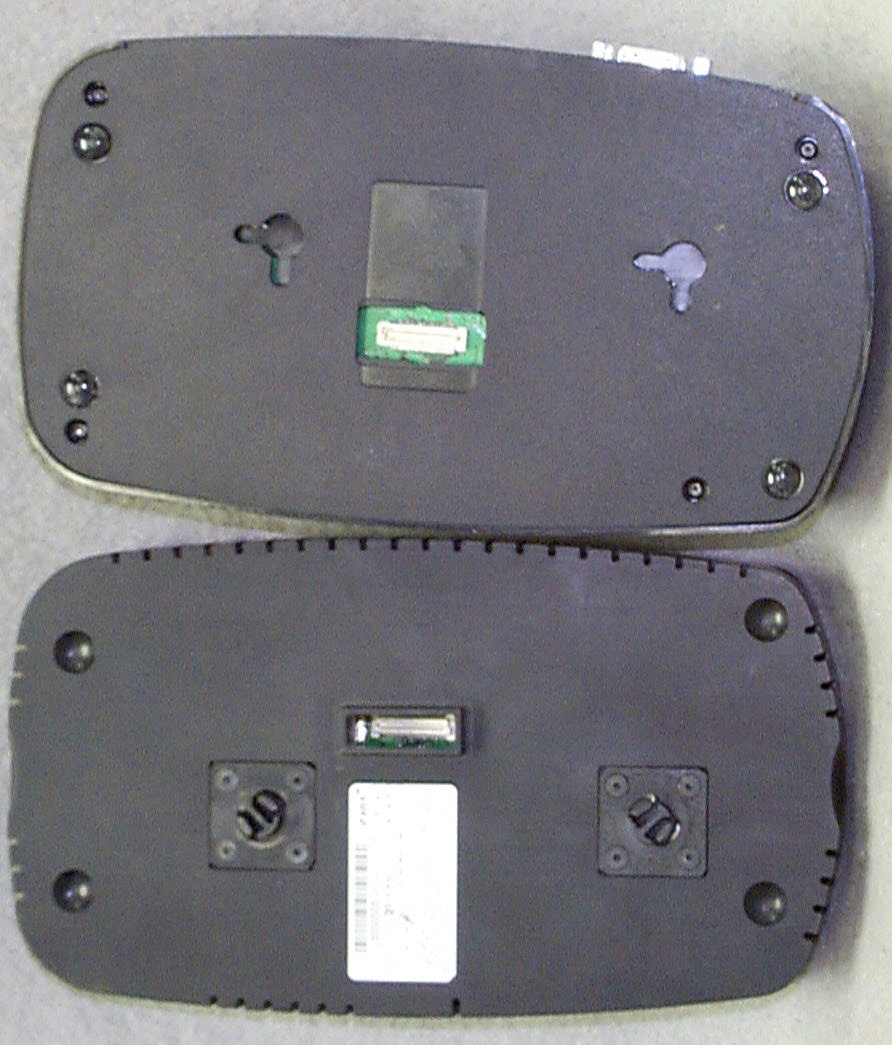
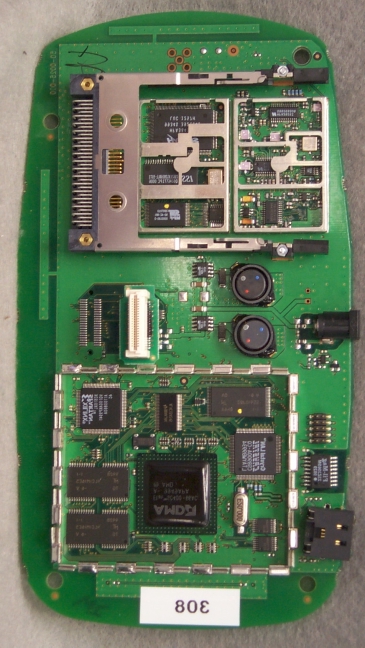
FCC ID: NSK0016B SECTION 5 PHOTOGRAPHS FCC ID: NSK0016B PHOTOS OF THE TESTED EUT The following photos are attached: Photo 1.Front View of EUT as Tested with NCU Photo 2.Rear View of EUT as Tested with NCU Photo 3.Side View of EUT as Tested with NCU, Showing Proper Connection of AC Power Photo 4.EUT (On Right), Separated from NCU Photo 5.EUT, Top View of Board Photo 6.EUT, Top View of Board with PCMCIA Card Removed Photo 7.EUT, Top View of Board with Shields Removed Photo 8.EUT, Bottom View of Board Photo 9.EUT, Bottom View of Board with Shields Removed Photo 10.Top of Connector Board Photo 11. Bottom of Connector Board Photo 12.Front View of EUT as a Stand Alone Product Photo 13.Rear View of EUT as a Stand Alone Product Photo 14.Side View of EUT as a Stand Alone Product, Showing Proper Connection of AC Power Photo 15.Top View of EUT as a Stand Alone Product, Top Cover Removed Photo 16.Top View of EUT as a Stand Alone Product, Secondary Cover Removed FCC ID: NSK0016B Photo 1. Front View of EUT as Tested with NCU FCC ID: NSK0016B Photo 2. Rear View of EUT as Tested with NCU FCC ID: NSK0016B Photo 3. Side View of EUT as Tested with NCU, Showing Proper Connection of AC Power FCC ID: NSK0016B Photo 4. EUT (On Right), Separated from NCU FCC ID: NSK0016B Photo 5. EUT, Top View of Board FCC ID: NSK0016B Photo 6. EUT, Top View of Board with PCMCIA Card Removed FCC ID: NSK0016B Photo 7. EUT, Top View of Board with Shields Removed
FCC ID: NSK0016B Photo 8. EUT, Bottom View of Board FCC ID: NSK0016B Photo 9. EUT, Bottom View of Board with Shields Removed FCC ID: NSK0016B Photo 10. Top of Connector Board FCC ID: NSK0016B Photo 11. Bottom of Connector Board FCC ID: NSK0016B Photo 12. Front View of EUT as a Stand Alone Product FCC ID: NSK0016B Photo 13. Rear View of EUT as a Stand Alone Product FCC ID: NSK0016B Photo 14. Side View of EUT as a Stand Alone Product, Showing Proper Connection of AC Power FCC ID: NSK0016B Photo 15.Top View of EUT as a Stand Alone Product, Top Cover Removed FCC ID: NSK0016B Photo 16.Top View of EUT as a Stand Alone Product, Secondary Cover Removed
RF Safety Requirements to 2.1091 for Mobile Transmitters According to Section 3 of Supplement C to OET Bulletin 65, Part 15 Transmitters are categorically excluded from Routine Environmental Evaluation by measurement or precise computations unless otherwise required by the Commissions The unit under evaluation has 2 internal antennas of 0 dBi gain (for Diversity) with a measured output power output of 0.235 Watts at the antenna terminals. Additionally, page 7 of the users manual specifies to install the device at least 20 cm away from the users or other individuals. Due to the low power of the EUT, environmental evaluation should be deemed unnecessary since the EUT’s operational frequency range is 2.4-2.4835 GHz and the ERP is considerably less than 3 Watts.
Processing Gain for the HWN TransPort The radio transmitter and receiver in the Home Wireless Networks TransPort Wireless LAN Access Point is capable of operation at over-the-air data rates of 1 MBPS, 2 MBPS, 5.5 MBPS, and 11 MBPS. The following table illustrates the differences in modulation, data, and symbol rates for each mode: Data Ra tes and Mod ulation HWN Tra nsPort Data Rate (MBPS) Mod ulationSymbol Rate (MSPS) Chip Rate (MCPS) Spreading Gain (dB) Coding Gain (dB) Theoretical Processing Gain (dB) Theoretical Es/No at 10e-5 BER (dB) Mini mum J/S ratio for 10 dB processing gain (dB) (with 2 dB allowable system loss) 1BPSK11110.4010.411 - 3 2QPSK11110.4010.411-3 5.5CCK1.37589.02.211.216.2-8.2 11CCK1.37589.02.211.216.4-8.4 The performance of the HWN TransPort has been tested in accordance with the CW jamming margin test of FCC rules Part 15.247(e). Below is a summary of the theoretical basis behind the performance of the equipment at the 5.5 and 11 MBPS modes with 8 chips/symbol. Performance of the 1 and 2 MBPS modes is based upon the calculations given in 15.247(e) at 11 chips per symbol and does not require additional theoretical basis. Theoretical calculations for 5.5 and 11 MBPS Modes The processing gain is re lated to the jamming margin as follows [2]: system output p L S J N S G + + = Where BER REFERENCE is the reference bit error ratio with its corresponding, theoretical output signal to noise ratio per symbol, (S/N) output , (J/ S) is the jamming margin (jamming signal power relative to desired signal power), and L system are the system implementation losses. The maximum allowed total system imple mentation loss is 2 dB. The HFA3860B direct sequence spread spectrum baseband processor uses CCK modulation for 5.5 and 11 MBPS modes, which is a form of M-ary Orthogonal Keying. The BER performance curve is given as: “ The probability of error for generalized M-ary Orthogona l signaling using coherent demodulation is given by: PPQz Ez dz ec b M S N =− =−−+ − − − ∞ ∫ 11 1 2 212 2 1 2 1 2 01 0 π η ()exp This integral cannot be solved in closed form, and numerical integration must be used. There are error rate extensions for differential decoding and descrambling that are also to be accounted for. This is done in a MATHCAD environment and is displayed in graphical format below. 1.11000 byte PER vs. Es/No 15.51616.517 10 -2 10 -1 10 0 11 Mbps CCK in Thermal Noise Es/No (dB) 1000 byte Packet Error Rate The reference PER is specified as 8% . The corresponding Es/No (signal to noise ratio per symbol) is 16.4 dB. The Es/No required to achieve the desired BER with maximum system implementation losses is 18.4 dB. The minimum processing gain is again, 10 dB, therefore: dB S J dBdBL S J N E G system output o s p 100.24.16 ≥ ++=+ + = dB S J dBG p 104.18 ≥ += The minimum ja mmer to signal ratio is as follows: dB S J 4.8 −≥ For the case of the HFA3860B, the bit rates are 1, 2, 5.5, and 11 Mbps. The corresponding symbol rates are 1, 1, 1.375, and 1.375 MSps. The chip rate is always 11 MCps, so the ratio of chip rate to symbol rate is 11:1 for the 1 and 2 Mbps rates and 8:1 for the 5.5 and 11 Mbps rates. Since the symbol rate to bit rate is less than 10 for the higher rates, we supply the theoretical processing gain calculation for these cases where spread spectrum processing gain with embedded coding gain is utilized. This is reasonable in that they cannot be separated in the demodulation process. If a separable FEC coding scheme were used, we would not be comfortable making this assertion. As can be seen from the curve of figure 1, the Es/N0 is 16.4 dB at the PER of 8%. This PER can be related to a BER of 1e-5 on 1000 byte packets. With 8 bits per symbol, the Eb/N0 is then 7.4 dB or 9 dB less than the Es/N0. It is well known that the Eb/N0 of BPSK is 9.6 dB for 1e-5 BER, so therefore the coding gain of CCK over BPSK is 2.2 dB. We add this to the processing gain of 9 dB to get 11.2 dB overall processing gain for the CW jammer test. Taking the calculations above, if the J/S >= -8.4 dB then the equipment passes the CW jamming test in 11 MBPS modes. For 5.5 MBPS modes, the HFA3860B data sheet shows that the required Es/No is 0.2 dB less than that required for the 11 MBPS mode. Thus if the J/S >= -8.2 dB then the equipment passes the CW jamming test in 5.5 MBPS modes.
Home Wireless Networks, Inc. FCC Part 15, Certification Application 95-0016-XXX May 25, 2000 MEASUREMENT/TECHNICAL REPORT COMPANY NAME: Home Wireless Networks, Inc. MODEL: 95-0016-XXX FCC ID: NSK0016B DATE: May 25, 2000 This report concerns (check one): Original grant X Class II change_____ Equipment type: Direct Sequence Spread Spectrum Deferred grant requested per 47 CFR 0.457(d)(1)(ii)? yes_____ No X If yes, defer until:_________________ date N.A. agrees to notify the Commission by N.A. date of the intended date of announcement of the product so that the grant can be issued on that date. Report prepared by: United States Technologies, Inc. 3505 Francis Circle Alpharetta, GA 30004 Phone Number: (770) 740-0717 Fax Number: (770) 740-1508 FCC ID: NSK0016B TABLE OF CONTENTS AGENCY AGREEMENT LETTER OF CONFIDENTIALITY SECTION 1 GENERAL INFORMATION 1.1 Product Description 1.2 Related Submittal(s) SECTION 2 TESTS AND MEASUREMENTS 2.1 Configuration of Tested EUT 2.2 Test Facility 2.3 Test Equipment 2.4 Modifications 2.5 Test Procedure and Results 2.6 Antenna Description 2.7 Peak Power (Antenna Conducted at Antenna Terminal) 2.8 Antenna Conducted Spurious Emissions 2.9 Peak Radiated Spurious Emissions 2.10 Average Radiated Spurious Emissions 2.11 Minimum 6 dB Bandwidth 2.12 Power Spectral Density 2.13 Processing Gain 2.14 Power Line Conducted Emissions for Transmitter SECTION 3 LABELING INFORMATION SECTION 4 BLOCK DIAGRAM(S)/ SCHEMATIC(S) SECTION 5 PHOTOGRAPHS SECTION 6 USER'S MANUAL FCC ID: NSK0016B LIST OF FIGURES AND TABLES FIGURES 1)Test Configuration 2) Photograph(s) for Spurious and Conducted Emissions 3) Peak Power Output 4) Antenna Conducted Spurious Emissions 5) Peak Radiated Spurious Emissions 6) Average Radiated Spurious Emissions 7) 6 dB Bandwidth 8) Power Spectral Density TABLES 1)EUT and Peripherals 2) Test Instruments 3) Peak Power Output 4) Peak Radiated Spurious Emissions 5) Average Radiated Spurious Emissions 6) 6 dB Bandwidth 7) Power Spectral Density 8) Conducted Emissions Data FCC ID: NSK0016B SECTION 1 GENERAL INFORMATION FCC ID: NSK0016B GENERAL INFORMATION 1.1Product Description The Equipment Under Test (EUT) is a Home Wireless Networks, Inc., Model 95-0016-XXX. The Model 95-0016-XXX is an IEEE 802.11 Wireless Ethernet Transceiver Module (2.4 GHz) with diversity which may be used as either a self contained unit or attached to Home Wireless Networks, Inc. NCU controller (model 95-0005-XXX) for added functionality and communication with other Home Wireless Networks, Inc. products. When utilized as a self contained unit, the EUT obtains power through use of an external AC adapter. Units used with a NCU controller are connected directly to the bottom side of the NCU and obtain their power from the NCU through the interface connecting the two units. The following is a list of the channels designed into the EUT: RF Frequencies HWN IEEE 802.11 Wireless Ethernet Module RF CHANNEL TRANSMIT/RECEIVE FREQUENCY (MHZ) RF LOCAL OSCILLATOR FREQUENCY (Internal radio version only) 124122038 224172043 324222048 424272053 524322058 624372063 724422068 824472073 924522078 1024572083 1124622088 FCC ID: NSK0016B 1.2Related Submittal(s)/Grant(s) The EUT will be used with part of a system to send/receive data. The transceiver presented in this report will be used with other like transceivers. The EUT may also be used along with a Home Wireless Networks, Inc. Model 95-0005-XXX which has been previously submitted and approved under FCC ID: NSK0005A. The EUT is subject to the following authorizations: a) Certification as a transmitter b) Certification or DoC as a computer peripheral device c) Verification as a receiver and digital device The information contained in this report is presented for the certification portion of the EUT. A separate report (UST # 00-0173) has been issued which covers the requirements for the DoC & verification authorization(s) for the EUT. FCC ID: NSK0005A SECTION 2 TESTS AND MEASUREMENTS FCC ID: NSK0005A TEST AND MEASUREMENTS 2.1 Configuration of Tested System The sample was tested per ANSI C63.4, Methods of Measurement from Low-Voltage Electrical and Electronic Equipment in the Range of 9 kHz to 40 GHz (1992). Conducted and radiated emissions data were taken with the test receiver or spectrum analyzer's resolution bandwidth adjusted to 9 kHz and 120 kHz, respectively. All measurements are peak unless stated otherwise. The video filter associated with the spectrum analyzer was off throughout the evaluation process. Interconnecting cables were manipulated as necessary to maximize emissions. Interconnecting cables were manipulated as necessary to maximize emissions. A block diagram of the tested system is shown in Figure 1. Test configuration photographs for spurious and fundamental emissions are shown in Figure 2. The EUT is internally identical for both versions (self contained versus for use with NCU). The unit that connects to a NCU controller was selected for testing since it consists of additional electrical devices connected to the EUT. Since AC power is supplied either directly to the unit in a self contained configuration, or through the NCU when used in it is connected to the EUT, two separate conducted emissions tests were performed. The sample used for testing was received by U.S. Technologies on April 19, 2000 in good condition. 2.2 Test Facility Testing was performed at US Tech's measurement facility at 3505 Francis Circle, Alpharetta, GA. This site has been fully described and submitted to the FCC, and accepted in their letter marked 31040/SIT. Additionally this site has also been fully described and submitted to Industry Canada (IC), and has been approved under file number IC2982. 2.3 Test Equipment Table 2 describes test equipment used to evaluate this product. 2.4 Modifications No modifications were made by US Tech, to bring the EUT into compliance with FCC Part 15 limits for the transmitter portion of the EUT. FCC ID: NSK0005A FIGURE 1a TEST CONFIGURATION…
Text truncated - open the document above for the full version.
FCC ID: NSK0016B 2.11 Minimum 6 dB Bandwidth per FCC Section 15.247(a)(2) The minimum requirement is given in Figure 7a through 7f. If the EUT incorporates different spreading codes or data rates these were each investigated and the one which produced the smallest 6 dB bandwidth was selected for test. FCC ID: NSK0016B Figure 7a. 6 dB Bandwidth per FCC Section 15.247(a)(2) (Antenna A - Low) FCC ID: NSK0016B Figure 7b. 6 dB Bandwidth per FCC Section 15.247(a)(2) (Antenna A - Mid) FCC ID: NSK0016B Figure 7c. 6 dB Bandwidth per FCC Section 15.247(a)(2) (Antenna A - High) FCC ID: NSK0016B Figure 7d. 6 dB Bandwidth per FCC Section 15.247(a)(2) (Antenna B - Low) FCC ID: NSK0016B Figure 7e. 6 dB Bandwidth per FCC Section 15.247(a)(2) (Antenna B - Mid) FCC ID: NSK0016B Figure 7f. 6 dB Bandwidth per FCC Section 15.247(a)(2) (Antenna B - High) FCC ID: NSK0016B 2.12 Power Spectral Density FCC Section 15.247(b) and 15.247(d) The transmitter power spectral density averaged over any 1 second interval is given in Table 7 and Figure 8a through Figure 8f. If the EUT incorporates different spreading codes or data rates these were each investigated and the one which produced the smallest 6 dB bandwidth was selected for test. The measurement was made using a spectrum analyzer utilizing noise marker mode. A 34.8 dBm adjustment has been added to the measurement to correct from 1 Hz to 3 kHz measurement. FCC ID: NSK0016B TABLE 7 POWER SPECTRAL DENSITY Test Date:April 28 UST Project:00-0161 Customer:Home Wireless Networks, Inc. Model:95-0016-XXX Antenna A Frequency (GHz) Test Data (dBm) Normalized to 1 Hz Results (dBm) FCC Limit (dBm) 2.413-53.7-18.98.0 2.438-51.5-16.78.0 2.461-52.4-17.68.0 Antenna B Frequency (GHz) Test Data (dBm) Normalized to 1 Hz Results (dBm) FCC Limit (dBm) 2.413-56.2-21.48.0 2.438-51.7-16.98.0 2.461-52.7-17.98.0 Note: 34.8 dBm has been added to correct from 1 Hz to 3 kHz Tester Signature: Name: Tim R. Johnson FCC ID: NSK0016B Figure 8a Power Spectral Density 15.247(b) and 15.247(d) (Antenna A – Low) FCC ID: NSK0016B Figure 8b Power Spectral Density 15.247(b) and 15.247(d) (Antenna A – Mid) FCC ID: NSK0016B Figure 8c Power Spectral Density 15.247(b) and 15.247(d) (Antenna A – High) FCC ID: NSK0016B Figure 8d Power Spectral Density 15.247(b) and 15.247(d) (Antenna B – Low) FCC ID: NSK0016B Figure 8e Power Spectral Density 15.247(b) and 15.247(d) (Antenna B – Mid) FCC ID: NSK0016B Figure 8f Power Spectral Density 15.247(b) and 15.247(d) (Antenna B – High) FCC ID: NSK0016B 2.13 Processing Gain Data regarding processing gain has been provided on the following page from Home Wireless Networks, Inc. FCC ID: NSK0016B This has been provided in separate files FCC ID: NSK0016B 2.14 Power Line Conducted Emissions for Transmitter FCC Section 15.207 The conducted voltage measurements have been carried out in accordance with FCC Section 15.207, with a spectrum analyzer connected to a LISN and the EUT placed into a continuous mode of transmit. The results are given in Table 8. FCC ID: NSK0016B TABLE 8a. CONDUCTED EMISSIONS DATA CLASS B Test Date:April 19, 2000 UST Project: 00-0161 Customer: Home Wireless Networks, Inc. Product: 95-0016-XXX Configuration with NCU (AC Adapter attached to NCU) Frequency (MHz) Test Data (dBm) Phase Neutral RESULTS (uV) Phase Neutral FCC Limits (uV) 0.45-81.0-78.719.926.0250 2.9-68.6-67.183.298.9250 5.9-83.6-81.514.818.8250 11.7-83.1-83.515.714.9250 13.7-76.6-71.633.158.9250 15.2-78.0-75.728.236.7250 SAMPLE CALCULATIONS: RESULTS uV = ANTILOG ((-81.0 + 107)/20) = 19.9 CONVERSION FROM dBm TO dBuV = 107 dB Test Results Reviewed By Signature: Name: Tim R. Johnson FCC ID: NSK0016B TABLE 8b. CONDUCTED EMISSIONS DATA CLASS B Test Date:April 19, 2000 UST Project: 00-0161 Customer: Home Wireless Networks, Inc. Product: 95-0016-XXX Configuration as self contained unit (AC Adapter attached to EUT) Frequency (MHz) Test Data (dBm) Phase Neutral RESULTS (uV) Phase Neutral FCC Limits (uV) 0.71-79.2-77.424.530.2250 3.0-69.1-65.978.5113.5250 3.4-72.5-76.653.133.1250 11.7-79.6-76.923.431.9250 13.7-75.2-74.838.940.7250 15.2-79.8-68.522.984.1250 SAMPLE CALCULATIONS: RESULTS uV = ANTILOG ((-79.2 + 107)/20) = 24.5 CONVERSION FROM dBm TO dBuV = 107 dB Test Results Reviewed By Signature: Name: Tim R. Johnson
FCC ID: NSK0016B 2.8 Antenna Conducted Spurious Emission in the Frequency Range 30 - 25000 MHz (FCC Section 15.247(c)) Antenna conducted spurious emissions in the frequency range 30-25000 MHz have been measured with a spectrum analyzer by connecting the spectrum analyzer directly via a short cable to the antenna output terminals or across the antenna leads on the PCB as specified by the manufacturer. The spectrum analyzer was set for a 50 Ω impedance with the RBW = 100 kHz & VBW > RBW. All spurious emissions were measured to be greater than 20 dB down from the fundamental. The results of conducted spurious emissions are given in Figure 4a through Figure 4x. FCC ID: NSK0016B Figure 4a Antenna Conducted Spurious Emissions 15.247(c) (Antenna A - Low) FCC ID: NSK0016B Figure 4b Antenna Conducted Spurious Emissions 5.247(c) (Antenna A - Low) FCC ID: NSK0016B Figure 4c Antenna Conducted Spurious Emissions 15.247(c) (Antenna A - Low) FCC ID: NSK0016B Figure 4d Antenna Conducted Spurious Emissions 15.247(c) (Antenna A - Low) FCC ID: NSK0016B Figure 4e Antenna Conducted Spurious Emissions 15.247(c) (Antenna A - Mid) FCC ID: NSK0016B Figure 4f Antenna Conducted Spurious Emissions 15.247(c) (Antenna A - Mid) FCC ID: NSK0016B Figure 4g Antenna Conducted Spurious Emissions 15.247(c) (Antenna A - Mid) FCC ID: NSK0016B Figure 4h Antenna Conducted Spurious Emissions 15.247(c) (Antenna A - Mid) FCC ID: NSK0016B Figure 4i Antenna Conducted Spurious Emissions 15.247(c) (Antenna A - High) FCC ID: NSK0016B Figure 4j Antenna Conducted Spurious Emissions 15.247(c) (Antenna A - High) FCC ID: NSK0016B Figure 4k Antenna Conducted Spurious Emissions 15.247(c) (Antenna A - High) FCC ID: NSK0016B Figure 4l Antenna Conducted Spurious Emissions 15.247(c) (Antenna A - High) FCC ID: NSK0016B Figure 4m Antenna Conducted Spurious Emissions 15.247(c) (Antenna B - Low) FCC ID: NSK0016B Figure 4n Antenna Conducted Spurious Emissions 5.247(c) (Antenna B - Low) FCC ID: NSK0016B Figure 4o Antenna Conducted Spurious Emissions 15.247(c) (Antenna B - Low) FCC ID: NSK0016B Figure 4p Antenna Conducted Spurious Emissions 15.247(c) (Antenna B - Low) FCC ID: NSK0016B Figure 4q Antenna Conducted Spurious Emissions 15.247(c) (Antenna B - Mid) FCC ID: NSK0016B Figure 4r Antenna Conducted Spurious Emissions 15.247(c) (Antenna B - Mid) FCC ID: NSK0016B Figure 4s Antenna Conducted Spurious Emissions 15.247(c) (Antenna B - Mid) FCC ID: NSK0016B Figure 4t Antenna Conducted Spurious Emissions 15.247(c) (Antenna B - Mid) FCC ID: NSK0016B Figure 4u Antenna Conducted Spurious Emissions 15.247(c) (Antenna B - High) FCC ID: NSK0016B Figure 4v Antenna Conducted Spurious Emissions 15.247(c) (Antenna B - High) FCC ID: NSK0016B Figure 4w Antenna Conducted Spurious Emissions 15.247(c) (Antenna B - High) FCC ID: NSK0016B Figure 4x Antenna Conducted Spurious Emissions 15.247(c) (Antenna B - High)
FCC ID: NSK0016B 2.9 Peak Radiated Spurious Emission in the Frequency Range 30 - 25000 MHz (FCC Section 15.247(c)) A preliminary scan was performed on the EUT to determine frequencies that were caused by the transmitter portion of the product. Significant emissions that fell within restricted bands were then measured on an OAT’s site. Radiated measurements below 1 GHz were tested with a RBW = 120 kHz. Radiated measurements above 1 GHz were measured using a RBW = VBW = 1 MHz. The results of peak radiated spurious emissions falling within restricted bands are given in Table 4a & 4d (low), Table 4b & 4e, (mid), Table 4c & 4f (high) and Figure 5a – 5f. FCC ID: NSK0016B Figure 5a Peak Radiated Spurious Emission 15.247(c) (Antenna A – Low) FCC ID: NSK0016B Figure 5b Peak Radiated Spurious Emission 15.247(c) (Antenna A – Mid) FCC ID: NSK0016B Figure 5c Peak Radiated Spurious Emission 15.247(c) (Antenna A – High) FCC ID: NSK0016B Figure 5d Peak Radiated Spurious Emission 15.247(c) (Antenna B – Low) FCC ID: NSK0016B Figure 5e Peak Radiated Spurious Emission 15.247(c) (Antenna B – Mid) FCC ID: NSK0016B Figure 5f Peak Radiated Spurious Emission 15.247(c) (Antenna B – High) FCC ID: NSK0016B TABLE 4a PEAK RADIATED SPURIOUS EMISSIONS (Antenna A - Low) Test Date:May 1, 2000 UST Project:00-0161 Customer:Home Wireless Networks, Inc. Model:95-0016-XXX Freq. (GHz) Test Data (dBm) @3m High Pass Filter Loss (dB) Amp. Gain (dB) Antenna Factor (dB) Cable Loss (dB) Results (uV/m) @3m FCC Limits (uV/m) @3m 4.824-62.01.034.234.77.9524.85000 SAMPLE CALCULATION: RESULTS (uV/m @ 3m) = Antilog ((-62.0 + 1.0 - 34.2 + 34.7 + 7.9 + 107)/20) = 524.8 CONVERSION FROM dBm TO dBuV = 107 dB Test Results Reviewed By Signature: Name: Tim R. Johnson FCC ID: NSK0016B TABLE 4b PEAK RADIATED SPURIOUS EMISSIONS (Antenna A - Mid) Test Date:May 1, 2000 UST Project:00-0161 Customer:Home Wireless Networks, Inc. Model:95-0016-XXX Freq. (GHz) Test Data (dBm) @3m High Pass Filter Loss (dB) Amp. Gain (dB) Antenna Factor (dB) Cable Loss (dB) Results (uV/m) @3m FCC Limits (uV/m) @3m 4.874-61.91.034.134.88.1555.95000 SAMPLE CALCULATION: RESULTS (uV/m @ 3m) = Antilog ((-61.9 + 1.0 - 34.1 + 34.8 + 8.1 + 107)/20) = 555.9 CONVERSION FROM dBm TO dBuV = 107 dB Test Results Reviewed By Signature: Name: Tim R. Johnson FCC ID: NSK0016B TABLE 4c PEAK RADIATED SPURIOUS EMISSIONS (Antenna A - High) Test Date:May 1, 2000 UST Project:00-0161 Customer:Home Wireless Networks, Inc. Model:95-0016-XXX Freq. (GHz) Test Data (dBm) @3m High Pass Filter Loss (dB) Amp. Gain (dB) Antenna Factor (dB) Cable Loss (dB) Results (uV/m) @3m FCC Limits (uV/m) @3m 4.934-64.31.034.134.98.2431.55000 SAMPLE CALCULATION: RESULTS (uV/m @ 3m) = Antilog ((-64.3 + 1.0 - 34.1 + 34.9 + 8.2 + 107)/20) = 431.5 CONVERSION FROM dBm TO dBuV = 107 dB Test Results Reviewed By Signature: Name: Tim R. Johnson FCC ID: NSK0016B TABLE 4d PEAK RADIATED SPURIOUS EMISSIONS (Antenna B - Low) Test Date:May 1, 2000 UST Project:00-0161 Customer:Home Wireless Networks, Inc. Model:95-0016-XXX Freq. (GHz) Test Data (dBm) @3m High Pass Filter Loss (dB) Amp. Gain (dB) Antenna Factor (dB) Cable Loss (dB) Results (uV/m) @3m FCC Limits (uV/m) @3m 4.824-59.21.034.234.77.9724.45000 SAMPLE CALCULATION: RESULTS (uV/m @ 3m) = Antilog ((-59.2 + 1.0 - 34.2 + 34.7 + 7.9…
Text truncated - open the document above for the full version.
3505 Francis Circle · Alpharetta, Georgia · United States
| # | Rule Parts | Frequency Range | Power Output |
|---|---|---|---|
| 1 | 15.247 | 2.41 GHz - 2.46 GHz | 134.00 mW |

DSS - Part 15 Spread Spectrum Transmitter
Equipment Class
DSS - Part 15 Spread Spectrum Transmitter