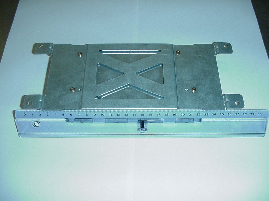
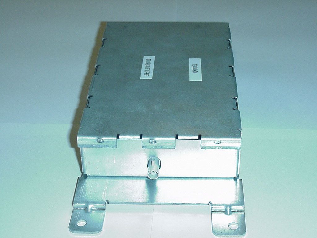
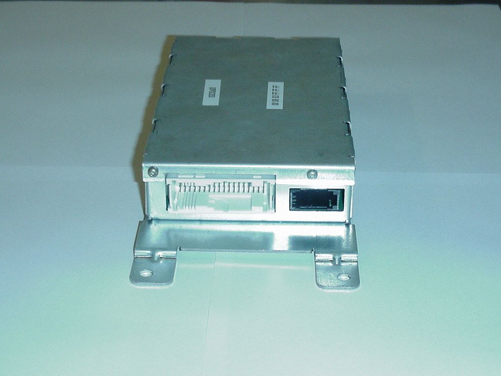
NT8-14B4093KAFSW2MACH Voice Link Bluetooth Subsystem (BT2), ULF
Visteon Corporation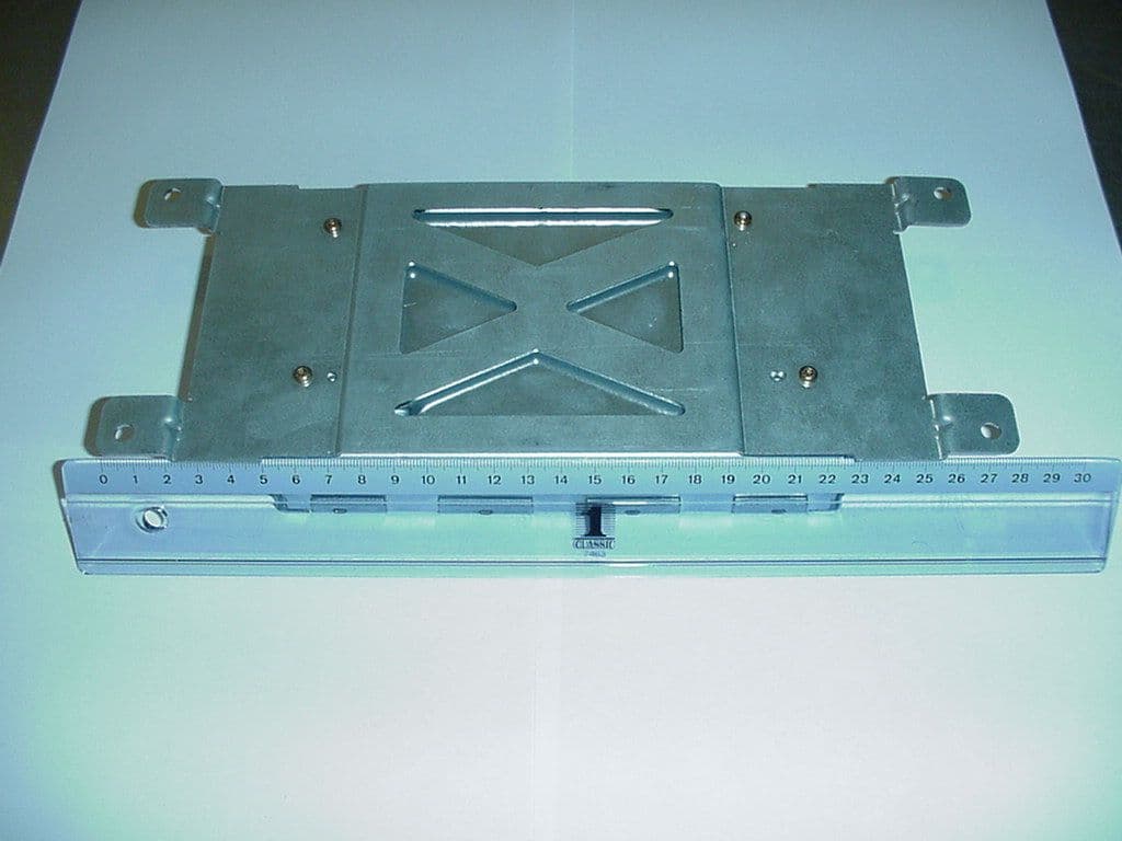
Click to zoom
Application Details
- Equipment Class
- DSS - Part 15 Spread Spectrum Transmitter
- Date of Grant
- Jul 27, 2003
- Application Purpose
- Original Equipment
- Date of Application
- Jul 27, 2003
- Equipment Note
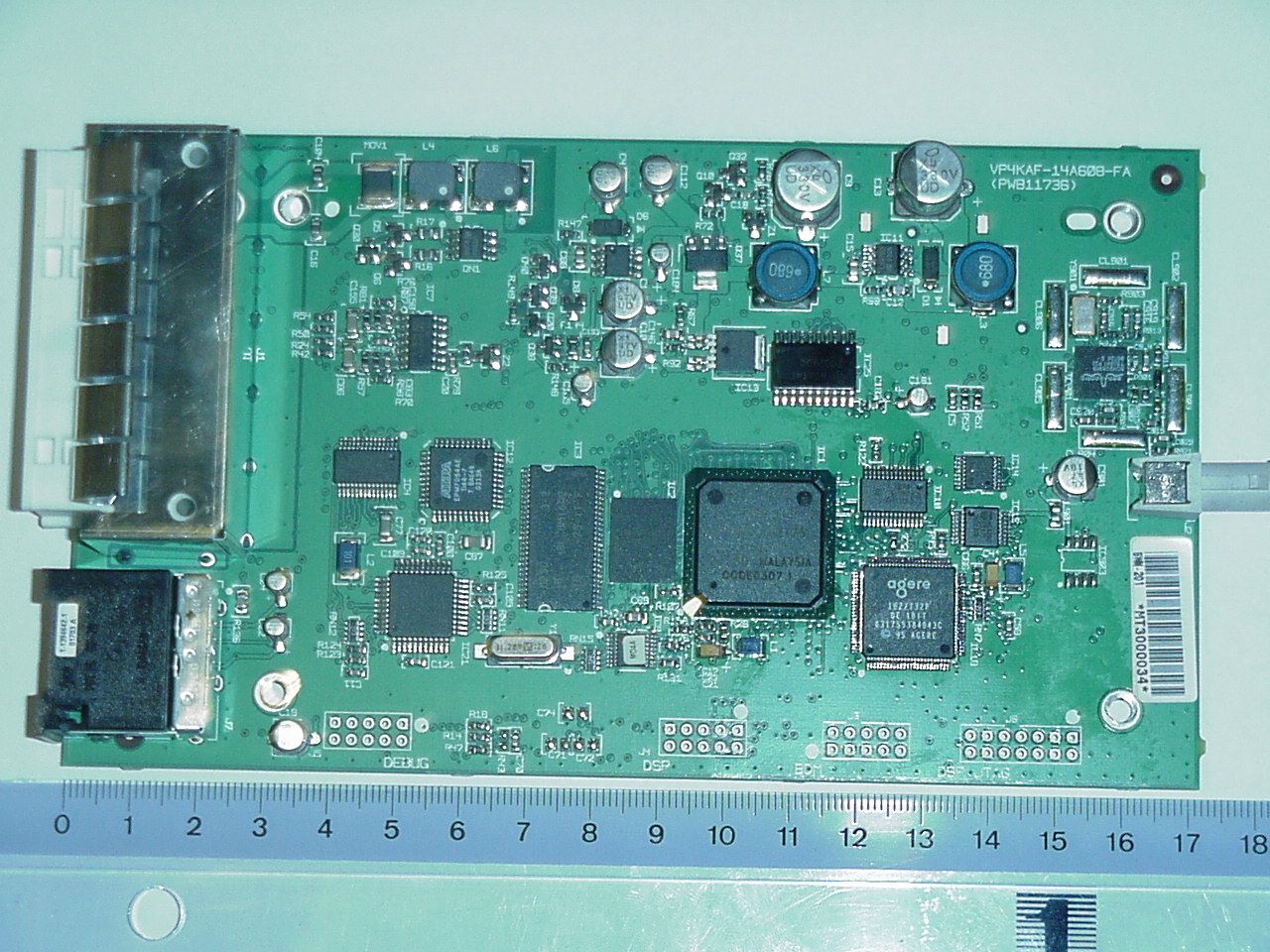
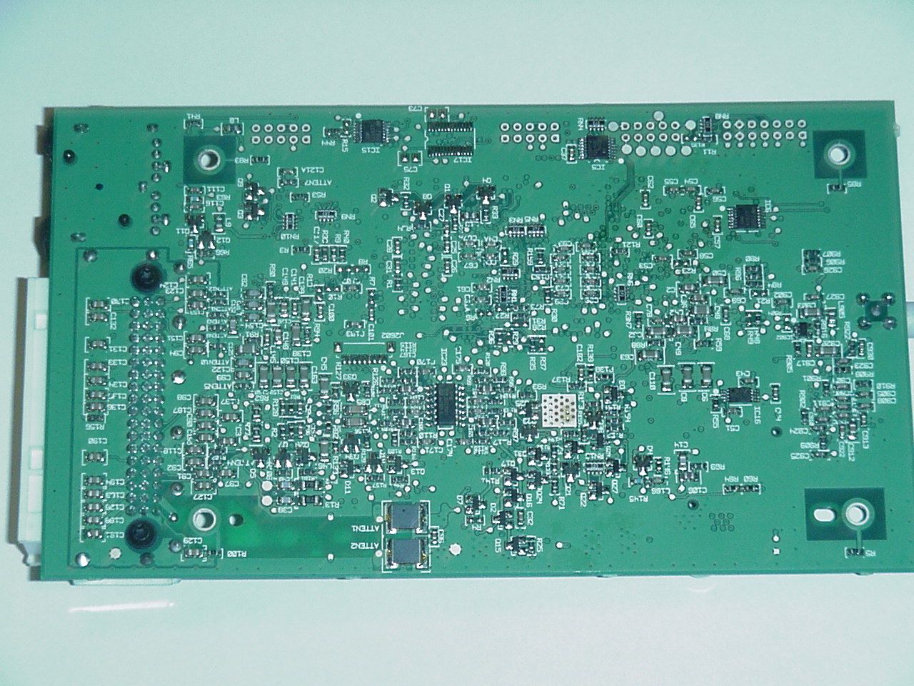
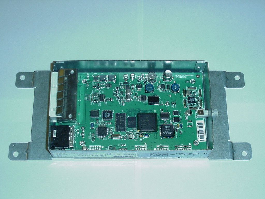
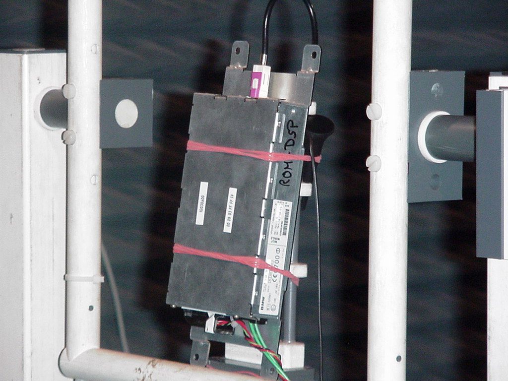
- MACH Voice Link Bluetooth Subsystem (BT2), ULF
- Frequency Range
- 2402.00000000 - 2480.00000000
- Company
- Visteon Corporation
- Country
- United States
Documents & Files
Document Text
Text extracted from the exhibit documents filed with the FCC. Open a document above to read the original.
Users Manual
Visteon Deutschland GmbH Bankverbindung Vorsitzender des Aufsichtsrates: Hans-Ulrich WilsingDeutsche Bank AG, Köln Sitz der Gesellschaft: Köln. Registergericht Köln. HRB 33551. Kto. Nr. 1902121/00 Geschäftsführung: Dr. Wilfried Janke (Vorsitzender), Simon Chau, Heribert DietzlerBLZ 370 700 60 USt. ID: DE 812 949 171 Visteon Deutschland GmbH Technologiezentrum Köln Weinsbergstrasse 195 D-50825 Köln Tel.: +49-(0)221-5406-550 Fax.: +49-(0)221-5406- www.visteon.com Visteon Deutschland GmbH D-50818 Köln 26 September 2002 Declaration for FCC warning statement Visteon Deutschland GmbH hereby declares, that for the product: SWIM XCVRPart Number: VP3KAF-14B409-A with the FCC ID: NT8-14B4093KAFSWM the following statement will be printed into the owners manual: Yours sincerely Gerhard Heyen Manager Body & Security Electronics This device complies with part 15 of the FCC Rules. Operation is subject to the following two conditions: (1) This device may not cause harmful interference, and (2) This device must accept any interference received, including interference that may cause undesired operation. Changes or modifications not expressly approved by the party responsible for compliance could void the user's authority to operate the equipment.
Users Manual
BetriebsanleitungzurUniversal Handy Vorbereitung © 2002 Bayerische Motoren Werke AktiengesellschaftMünchen/DeutschlandNachdruck, auch auszugsweise, nur mit schriftlicher Genehmigung der BMW AG, München. Bestell-Nr. 01 49 0 157 180VIII/02Printed in GermanyGedruckt auf umweltfreundlichem Papier– chlorfrei gebleicht, wiederverwertbar. 1 n Überblick, Kopplung, Entkopplung, Telefonbuch übertragen, Besonderheiten 3 Overview , Pairing, Isolating, Transfering phone book, Special features 9 Aperçu, Couplage, Découplage, Transfert du registre, Particularités 15 Sumario, Acoplamiento, Desacoplamiento, Transmitir listín telefónico, Particularidades 21 Panoramica, Collegamento, Scollegamento, Trasmissione rubrica, Particolarità 27 Överblick, Anslutning, Bortkoppling, Överföring av telefonbok, Speciella egenskaper 33 Overzicht, Koppeling, Ontkoppeling, Telefoonboek overnemen, Bijzonderheden 39 Oversigt, Kobling, Frakobling, Overføring af telefonbog, Egenskaber 45 Sumário, Acoplamento, Desacoplamento, Transmitir agenda, Particularidades 51 2 n 3 n Deutsch Hinweise zur BetriebsanleitungDiese Anleitung dient der Ergänzung der Fahrzeugbetriebsanleitung. Bewah-ren Sie diese zusammen mit Ihren anderen Fahrzeugunterlagen auf.Sollten Sie Ihren BMW eines Tages ver-kaufen wollen, denken Sie bitte daran, auch diese Anleitung zu übergeben – sie ist ein wichtiger Bestandteil des Fahrzeugs.Hinweise zu anderen Fahrzeugaus-stattungen entnehmen Sie bitte den Betriebsanleitungen Ihres Fahrzeugs oder den entsprechenden zusätzlichen Betriebsanleitungen. Bei Fragen hilft Ihnen Ihr BMW Service weiter. Aktualität bei DrucklegungFortschrittliche Technik und das hohe Qualitätsniveau der BMW Ausstattun-gen werden durch eine ständige Wei-terentwicklung gewährleistet. Daraus können sich evtl. Abweichungen zwischen dieser Betriebsanleitung und der Ausstattung Ihres Fahrzeugs erge-ben. Auch Irrtümer können wir nicht ganz ausschließen. Haben Sie deshalb bitte Verständnis dafür, dass aus den Angaben, Abbildungen und Beschrei-bungen keine juristischen Ansprüche hergeleitet werden können. Verwendete Symbole kennzeichnet Warnhinweise, die Sie unbedingt beachten sollten – aus Gründen Ihrer Sicherheit, der Sicherheit anderer und um Ihr Fahrzeug vor Schäden zu bewahren. < kennzeichnet Hinweise, die Sie auf Besonderheiten aufmerksam machen. < < kennzeichnet das Ende eines Hinweises.Wenn Sie weitere Fragen haben, wird Sie Ihr BMW Service jederzeit gern be-raten. 4 n ÜberblickDamit Sie Ihr Handy mit Bluetooth-Schnittstelle über Ihr Autoradio, Ihre Radionavigation oder Ihren Bordmoni-tor bedienen können, erhalten Sie auf den nachfolgenden Seiten Erläuterun-gen> zum Koppeln und Entkoppeln Ihres Handys an die Bluetooth-Schnitt-stelle Ihres Fahrzeugs > zur Übertragung des Telefonbuchs Ihres Handys an Ihr Autoradio, Ihre Radionavigation oder Ihren Bordmo-nitor > zu den Telefon-Funktionen, die Sie abhängig von Ihrem Handy oder Ihrem Autoradio, Ihrer Radionaviga-tion und Ihrem Bordmonitor nicht oder nur eingeschränkt nutzen kön-nen. Alle Eingaben bei stehendem Fahrzeug vornehmen. Sonst kann es zu einer Gefährdung der Insassen und anderer Verkehrsteilnehmer kom-men. < VoraussetzungenWenn Ihr Handy über eine Bluetooth-Schnittstelle verfügt, können Sie Ihr Handy an die Bluetooth-Schnittstelle Ihres Fahrzeugs koppeln. Erkundigen Sie sich beim BMW Service, welche Handys von der Universal Handy Vorbereitung unter-stützt und für welche Handys Handy-Aufnahmen angeboten werden. Diese Handy-Aufnahme ermöglicht Ihnen, das Handy zu laden und gewährleistet ei-nen besseren Netzempfang.Die Bluetooth Technologie darf nicht in allen Ländern verwendet werden. Er-kundigen Sie sich beim BMW Service, in welchen Ländern dies der Fall ist. < 5 n Deutsch KopplungHandy-Aufnahme einlegen Das Handy sollte vor jedem Gebrauch in die Handy-Auf- nahme gelegt werden, um ein einwand-freies Funktionieren sicherzustellen. < 1. Ablagefach entnehmen 2. Handy-Aufnahme für das Handy ein- legen und leicht nach unten drücken, bis es einrastet. Um die Handy-Aufnahme zu entneh-men:unterhalb der Handy-Aufnahme drücken. Handy einlegenHandy mit den Tasten nach oben einle-gen und leicht nach unten drücken, bis es einrastet.Um das Handy zu entnehmen:unterhalb der Handy-Aufnahme drücken.Sie können nun das Handy entnehmen. 6 n KopplungHandy koppeln Sie führen die Anmeldung Ihres Handys an die Bluetooth-Schnitt- stelle Ihres Fahrzeugs nur einmalig durch. Diese Anmeldung wird Kopplung genannt. Ihr gekoppeltes Handy wird in Zukunft automatisch erkannt und Sie können Ihr Handy über Ihr Radio, Ihre Radionavigation oder Ihren Bordmoni-tor bedienen. < Die Anzeigen im Display oder auf dem Bildschirm können je nach genutztem Gerät verschieden sein. < 1. Handy einschalten2. Die Taste oberhalb der Handy-Auf-nahme ca. eine Sekunde gedrückt haltenund gleichzeitig 3. Zündschlüssel in Stellung 1 drehen4. Taste loslassen. Im Display oder auf dem Bildschirm wird „BLUETOOTH KOPPLUNG“ angezeigt. Während des Kopplungsvor-gangs blinken am Bordmonitor oder am Autoradio mit Multi-Informationsdisplay die Kontroll-leuchten. < Abhängig vom verwendeten Handy werden Ihnen im Display Ihres Han-dys verschiedene Schritte vorgege-ben, die von Ihnen auszuwählen und zu bestätigen sind, siehe Betriebsanleitung Ihres Handys. Sie können bis zu vier Handys koppeln. Wenn Sie ein fünftes Handy koppeln, wird das Handy ge-löscht, das zuerst angemeldet wurde. < Während des Kopplungsvorgangs erscheint im Display Ihres Handys die Abfrage nach dem „BLUETOOTH PASSKEY“, einer 4-stelligen Num-mer, die Sie bei Auslieferung des Fahrzeugs erhalten. 5. Geben Sie über die Zifferntasten Ihres Handys den „BLUETOOTH PASSKEY“ ein.Im Display oder auf dem Bildschirm wird „ KOPPLUNG ERFOLGREICH“ angezeigt. Sie können jetzt oder zu einem späteren Zeitpunkt, die Einträge aus dem Telefonbuch Ihres Handys an Ihr Autoradio, Ihre Radio-navigation oder Ihren Bordmonitor übertragen, siehe Seite 8 . < 6. Zündschlüssel in Stellung 0 drehen. Die Kopplung Ihres Handys …
Text truncated - open the document above for the full version.
Users Manual
Registergericht? registered in: Vorstand? Board of Directors: 7 layers AG, Borsigstrasse 11 Düsseldorf, HRB 44096 Dr. Wolfgang Dahm 40880 Ratingen, Germany Aufsichtsratsvorsitzende ? Dr. Hans-Jürgen Meckelburg Phone: +49 (0) 2102 749 0 Chairman of the Supervisory Board: Fax: +49 (0) 2102 749 350 Dr. Sabine Grobecker www.7Layers.com Peter de Wit 27 June 2003 Phone +31 (0) 6 22 47 00 55 Fax +31 (0) 46 442 2192 RE: warning statement in manual of ‘Mach Voice Link Bluetooth Subsystem (BT2)’ model ULF, FCC-ID: NT8-14B4093KAFSW2 and model MULF, FCC-ID: NT8-14B4094KAFSW2 To Whom It May Concern: As formally appointed representative for the company Visteon (see electronic document H_ffc_confidentiality_request.pdf), we declare: A: the new ‘Mach Voice Link Bluetooth Subsystem (BT2)’ is functionally identical to the previously granted ‘Mach Voice Link Bluetooth Subsystem’ B: As the devices are identical the same manual will be provided with the new devices Therefor the declaration on the addition of the FCC warning text, as done by Visteon in electronic document Q_fcc_warning_statement.pdf, remains accurate and valid. Do not hesitate to contact me if you have any additional questions. Best Regards, Peter de Wit, Approvals Manager.
Cover Letter(s)
Registergericht? registered in: Vorstand? Board of Directors: 7 layers AG, Borsigstrasse 11 Düsseldorf, HRB 44096 Dr. Wolfgang Dahm 40880 Ratingen, Germany Aufsichtsratsvorsitzende ? Dr. Hans-Jürgen Meckelburg Phone: +49 (0) 2102 749 0 Chairman of the Supervisory Board: Fax: +49 (0) 2102 749 350 Dr. Sabine Grobecker www.7Layers.com Peter de Wit 27 June 2003 Phone +31 (0) 6 22 47 00 55 Fax +31 (0) 46 442 2192 RE: CONFIDENTIALITY REQUEST FOR ‘Mach Voice Link Bluetooth Subsystem (BT2)’ model ULF, FCC-ID: NT8-14B4093KAFSW2 and model MULF, FCC-ID: NT8-14B4094KAFSW2 To Whom It May Concern: As formally appointed representative for the company Visteon and in line with the confidentiality request from Visteon for the previous version of the ‘Mach Voice Link Bluetooth Subsystem’ (see electronic document H_ffc_confidentiality_request.pdf), this letter serves as an official request for confidentiality under the FCC Rule Section 0.459. We have requested that the schematic diagrams, parts list and block diagram, required to be submitted with this application, be withheld from public review. The reason for this request is that these documents are company proprietary information that should never get into the possession of competitors, which would be harmful for our business. Do not hesitate to contact me if you have any additional questions. Best Regards, Peter de Wit, Approvals Manager. Attn: Reviewing Engineer Federal Communications Commission 7435 Oakland Mills Road Columbia, MD 21046
Cover Letter(s)
Visteon Deutschland GmbH Bankverbindung Vorsitzender des Aufsichtsrates: Hans-Ulrich WilsingDeutsche Bank AG, Köln Sitz der Gesellschaft: Köln. Registergericht Köln. HRB 33551. Kto. Nr. 1902121/00 Geschäftsführung: Dr. Wilfried Janke (Vorsitzender), Simon Chau, Heribert DietzlerBLZ 370 700 60 USt. ID: DE 812 949 171 Visteon Deutschland GmbH Technologiezentrum Köln Weinsbergstrasse 195 D-50825 Köln Tel.: +49-(0)221-5406-550 Fax.: +49-(0)221-5406- www.visteon.com Visteon Deutschland GmbH D-50818 Köln Attn: Reviewing Engineer Federal Communications Commission 7435 Oakland Mills Road Columbia, MD 21046 26 September 2002 RE: CONFIDENTIALITY REQUEST FOR ‘Mach Voice Link Bluetooth Subsystem’, FCC-ID: NT8-14B4093KAFSWM To Whom It May Concern: This letter serves as an official request for confidentiality under the FCC Rule Section 0.459. We have requested that the schematic diagrams, parts list and Block (exhibit E, F, G) required to be submitted with this application be withheld from public review. The reason for this request is that these documents are company proprietary information that should never get into the possession of competitors, which would be harmful for our business. Do not hesitate to contact me if you have any additional questions. Thank you very much. Yours sincerely Gerhard Heyen Manager Body & Security Electronics
RF Exposure Info
Registergericht h registered in:Vorstand h Board of Directors:7 layers AG, Borsigstrasse 11 Ratingen, HRB 3264Dr. Wolfgang Dahm40880 Ratingen, Germany Aufsichtsratsvorsitzende h Dr. Hans-Jürgen MeckelburgPhone: +49 (0) 2102 749 0 Chairman of the Supervisory Board:Fax: +49 (0) 2102 749 350 Dr. Sabine Grobeckerwww.7Layers.com Peter de Wit 27 June 2003 Phone +31 6 22470055 Fax +31 46 4422192 RF exposure requirements - FCC ID: NT8-14B4093KAFSW2 and FCC ID: NT8-14B4094KAFSW2 Dear Application Examiner, The maximum measured power output is 0,703 mW (-1,53 dBm), the maximum antenna gain is 2 dBi = numeric gain 1,585 (see also FCC test report - Exhibit B) The maximum permissable exposure is defined in 47 CFR 1.1310 with 1 mW/cm². The distance from the EUT's transmitting antenna where the exposure level reaches the maximum permitted level is calculated using the general equation: S = P*G / 4πR² S max = 1mW/cm², P = 0,703 mW, linear power gain relative to the isotropic radiator = 2,0 dBi = 1,585 (numeric gain), R = distance in cm Solving for R, the 1mW/cm² limit is reached in a distance of 0,298 cm to the transmitting antenna. The module has to be integrated in a way that the minimum distance of 0,298 cm is ensured so a statement in the users manual is not necessary. Please contact us if you have any additional questions. Best Regards 7layers AG FCC Federal Communications Commission 2_VISGE_1703_TAS
Test Report
EMC Measurement/Technical Report on 2_VISGE_1703_TAS_FCCb 7 Layers AG Borsigstr. 11 40880 Ratingen Germany Note: The following test results relate only to the devices specified in this document. This report shall not be reproduced in parts without the written approval of the testing laboratory. Mach Bluetooth Voice Link Subsystem Most Module Registergericht - registered in: Düsseldorf, HRB 44096 Aufsichtratsvorsitzende - Chairman of the Supervisory Board: Dr. Sabine Grobecker Vorstand - Board of Directors: Dr. Wolfgang Dahm Dr. Hans-Jürgen Meckelburg 7 layers AG, Borsigstrasse 11 40880 Ratingen, Germany Phone: +49 (0) 2102 749 0 Fax: +49 (0) 2102 749 350 http://www.7Layers.com Report Reference: TTI-P-G 178/99 Test Laboratory (Headquarter): Interlab is a registered trademark of 7 layers AG Table of Contents 0. Summary 0.1 Technical Report Summary 0.2 Measurement Summary 1. Administrative Data 1.1 Testing Laboratory 1.2 Project Data 1.3 Applicant Data 1.4 Manufacturer Data 3. Testobject Data 3.1 General EUT Description 3.2 EUT Main Components 3.3 Ancillary Equipment 3.4 EUT Setups 3.5 Operating Modes 4. Measurement Results Conducted Emissions Occupied Bandwidth Peak Power Output Spurious RF Conducted Emissions 5. Testequipment 6. Foto Report 7. Setup Drawings 3 3 4 6 6 6 6 6 8 8 9 9 9 10 11 11 14 17 28 31 32 33 Spurious RF Radiated Emissions 19 2. Product Labeling 2.1 FCC ID Label 2.2 Location of Label on the EUT 7 7 7 Dwell Time Power Density Channel Separation Processing Gain 23 25 27 - 4.1 4.2 4.3 4.4 4.5 4.6 4.7 - 8. Annex Measurement plots25 Pages Page 2 of 58Testreport Reference: 2_VISGE_1703_TAS_FCCb 0 Summary 0.1 Technical Report Summary Type of Authorization Certification for an Intentional Radiator (Frequency Hopping Spread Spectrum) Applicable FCC Rules: Prepared in accordance with the requirements of FCC Rules and Regulations as listed in 47 CFR Ch.1 Parts 0 to 19 (10-1-98 Edition). The following subparts are applicable to the results in this test report. Part 2, Subpart J - Equipment Authorization Procedures, Certification Sections Part 15, Subpart C - Intentional Radiators § 15.201 Equipment authorization requirement § 15.207 Conducted limits § 15.209 Radiated emission limits; general requirements § 15.247 Operation within the bands 902-928 MHz, 2400-2483,5 MHZ and 5725-5850 MHz Summary Test Results: The EUT complied with all the applicable FCC rules as listed above. Note: The tests were selected and performed with reference to the FCC Public Notice DA 00- 705, released March 30, 2000 Page 3 of 58Testreport Reference: 2_VISGE_1703_TAS_FCCb 0.2 Measurement Summary § 15.247 (a) (1) (ii)FCC Part 15, Subpart C ANSI C63.41992 The measurement was performed according to Occupied Bandwidth OP-ModeSetupPortFinal Result setup 1op-mode 1Antenna connectorpassed setup 1op-mode 2Antenna connectorpassed setup 1op-mode 3Antenna connectorpassed setup 1op-mode 4Antenna connectorpassed setup 1op-mode 5Antenna connectorpassed § 15.247 (b) (1)FCC Part 15, Subpart C FCC §15.3110-1-1998 The measurement was performed according to Peak Power Output OP-ModeSetupPortFinal Result setup 1op-mode 1Antenna connectorpassed setup 1op-mode 2Antenna connectorpassed setup 1op-mode 3Antenna connectorpassed setup 1op-mode 4Antenna connectorpassed setup 1op-mode 5Antenna connectorpassed § 15.247 (c)FCC Part 15, Subpart C FCC §15.3110-1-1998 The measurement was performed according to Spurious RF Conducted Emissions OP-ModeSetupPortFinal Result setup 1op-mode 1Antenna connectorpassed setup 1op-mode 2Antenna connectorpassed setup 1op-mode 3Antenna connectorpassed § 15.247 (c), §15.35 (b), § 15.209FCC Part 15, Subpart C ANSI C63.41992 The measurement was performed according to Spurious Radiated Emissions OP-ModeSetupPortFinal Result setup 2op-mode 1Enclosurepassed setup 2op-mode 2Enclosurepassed setup 2op-mode 3Enclosurepassed § 15.247(f)FCC Part 15, Subpart C FCC §15.3110-1-1998 The measurement was performed according to Dwell Time OP-ModeSetupPortFinal Result setup 1op-mode 4Antenna connectorpassed setup 1op-mode 5Antenna connectorpassed § 15.247 (d)FCC Part 15, Subpart C Page 4 of 58Testreport Reference: 2_VISGE_1703_TAS_FCCb FCC §15.3110-1-1998 The measurement was performed according to Power Density OP-ModeSetupPortFinal Result setup 1op-mode 4Antenna connectorpassed setup 1op-mode 5Antenna connectorpassed § 15.247 (a) (1)FCC Part 15, Subpart C FCC §15.3110-1-1998 The measurement was performed according to Channel Separation OP-ModeSetupPortFinal Result setup 1op-mode 6Antenna connectorpassed Responsible for Accreditation Scope: Responsible for Test Report: Page 5 of 58Testreport Reference: 2_VISGE_1703_TAS_FCCb 1. Administrative Data 1.1 Testing Laboratory Company Name: Address: The test facility is also accredited by the following accreditation organisation: Responsible for Accreditation Scope: 7 Layers AG Borsigstr. 11 40880 Ratingen Germany DAR-Registration no. TTI-P-G 178/99 Dipl.-Ing Bernhard Retka Dipl.-Ing Arndt Stöcker Dipl.-Ing Thomas Hoell This facility has been fully described in a report submitted to the FCC and accepted under the registration number 96716. - Deutscher Akkreditierungs Rat 08.05.03 Dipl.-Ing. Thomas Hoell 18.06.03 27.05.-05.06.2003 Responsible for testing and report Receipt of EUT: Date of Test(s): Date of Report: 1.2 Project Data Visteon Automotive Systems Ron Schuchard 17000 Rotunda Drive MI 48121, Dearborn USA please see Applicant data 1.4 Manufacturer Data Company Name: Address: Contact Person: Company Name: Address: Contact Person: 1.3 Applicant Data Page 6 of 58Testreport Reference: 2_VISGE_1703_TAS_FCCb 2.0 Product Labeling 2.1 FCC ID Label: At the time of the report there was no FCC label available. 2.2 Location of Label on the EUT: see above Page 7 of 58Testreport Reference: 2_VISGE_1703_TAS_FCCb 3. Testobject Data Type Designation: Kind of Device: (optional) Voltage Type: Voltage level: Equipment under Test: Most Module Bluetooth transceiver Mach Bluetooth Voice Link Subsyst…
Text truncated - open the document above for the full version.
Test Report
Registergerichth registered in:Vorstandh Board of Directors:7 layers AG, Borsigstrasse 11 Ratingen HRB 3264Dr. Wolfgang Dahm40880 Ratingen, Germany AufsichtsratsvorsitzendehDr. Hans-Jürgen MeckelburgPhone: +49 (0) 2102 749 0 Chairman of the Supervisory Board:Fax: +49 (0) 2102 749 350 Dr. Sabine Grobeckerwww.7layers.com Annex Additional declaration part according FCC 15.247 for Bluetooth TM Devices Version: 2002-06-01 Annex - Additional declaration part according FCC 15.247 for Bluetooth devices Page 2 of 5 pages 1 Output power and channel separation of a Bluetooth device in the different operating modes: The different operating modes (data-mode, acquisition-mode) of a Bluetooth device don’t influence the output power and the channel spacing. There is only one transmitter which is driven by identical input parameters concerning these two parameters. Only a different hopping sequence will be used. For this reason the check of these RF parameters in one op-mode is sufficient. 2 Frequency range of a Bluetooth device: Hereby we declare that the maximum frequency of this device is: 2402 – 2480 MHz. This is according the Bluetooth Core Specification (+ critical errata) for devices which will be operated in the USA. This was checked during the Bluetooth Qualification tests (Test Case: TRM/CA/04-E). Other frequency ranges ( e.g. for Spain, France, Japan) which are allowed according the Core Specification are not supported by this device. 3 Co-ordination of the hopping sequence in data mode to avoid simultaneous occupancy by multiple transmitters: Bluetooth units which want to communicate with other units must be organised in a structure called piconet. This piconet consist of max. 8 Bluetooth units. One unit is the master the other seven are the slaves. The master co-ordinates frequency occupation in this piconet for all units. As the master hop sequence is derived from its BD address which is unique for each Bluetooth device, additional masters intending to establish new piconets will always use different hop sequences. 4 Example of a hopping sequence in data mode: Example of a 79 hopping sequence in data mode: 40, 21, 44, 23, 42, 53, 46, 55, 48, 33, 52, 35, 50, 65, 54, 67, 56, 37, 60, 39, 58, 69, 62, 71, 64, 25, 68, 27, 66, 57, 70, 59, 72, 29, 76, 31, 74, 61, 78, 63, 01, 41, 05, 43, 03, 73, 07, 75, 09, 45, 13, 47, 11, 77, 15, 00, 64, 49, 66, 53, 68, 02, 70, 06, 01, 51, 03, 55, 05, 04 Annex - Additional declaration part according FCC 15.247 for Bluetooth devices Page 3 of 5 pages 5 Equally average use of frequencies in data mode and behaviour for short transmissions: The generation of the hopping sequence in connection mode depends essentially on two input values: 1. LAP/UAP of the master of the connection 2. Internal master clock The LAP (lower address part) are the 24 LSB’s of the 48 BD_ADDRESS. The BD_ADDRESS is an unambiguous number of every Bluetooth unit. The UAP (upper address part) are the 24 MSB’s of the 48 BD_ADDRESS. The internal clock of a Bluetooth unit is derived from a free running clock which is never adjusted and is never turned off. For synchronisation with other units only offset are used. It has no relation to the time of the day. Its resolution is at least half the RX/TX slot length of 312.5 μs. The clock has a cycle of about one day (23h30). In most case it is implemented as 28 bit counter. For the deriving of the hopping sequence the entire LAP (24 bits), 4 LSB’s (4 bits) (Input 1) and the 27 MSB’s of the clock (Input 2) are used. With this input values different mathematical procedures (permutations, additions, XOR- operations) are performed to generate the sequence. This will be done at the beginning of every new transmission. Regarding short transmissions the Bluetooth system has the following behaviour: The first connection between the two devices is established, a hopping sequence was generated. For transmitting the wanted data the complete hopping sequence was not used. The connection ended. The second connection will be established. A new hopping sequence is generated. Due to the fact that the Bluetooth clock has a different value, because the period between the two transmission is longer (and it cannot be shorter) than the minimum resolution of the clock (312.5 μs). The hopping sequence will always differ from the first one. 6 Receiver input bandwidth and behaviour for repeated single or multiple packets: The input bandwidth of the receiver is 1 MHz. In every connection one Bluetooth device is the master and the other one is the slave. The master determines the hopping sequence (see chapter 5). The slave follows this sequence. Both devices shift between RX and TX time slot according to the clock of the master. Additionally the type of connection (e.g. single or multislot packet) is set up at the beginning of the connection. The master adapts its hopping frequency and its TX/RX timing according to the packet type of the connection. Also the slave of the connection will use these settings. Repeating of a packet has no influence on the hopping sequence. The hopping sequence generated by the master of the connection will be followed in any case. That means, a repeated packet will not be send on the same frequency, it is send on the next frequency of the hopping sequence. Annex - Additional declaration part according FCC 15.247 for Bluetooth devices Page 4 of 5 pages 7 Dwell time in data mode The dwell time of 0.3797s within a 30 second period in data mode is independent from the packet type (packet length). The calculation for a 30 second period is a follows: Dwell time = time slot length * hop rate / number of hopping channels *30s Example for a DH1 packet (with a maximum length of one time slot) Dwell time = 625 μs * 1600 1/s / 79 * 30s = 0.3797s (in a 30s period) For multislot packet the hopping is reduced according to the length of the packet. Example for a DH5 packet (with a maximum length of five time slots) Dwell time = 5 * 625 μs * 1600 * 1/5 *1/s / 79 * 30s = …
Text truncated - open the document above for the full version.
Contact Information
Applicant
Terry SanSouci(Product Assurance Test Engineer)
Technical Contact
Visteon Deutschland GmbHWerner Loebach
[email protected]+49 221 5406 0
Weinsbergstr. 195 · Cologne · Germany
Non-Technical Contact
Visteon Deutschland GmbHWerner Loebach
[email protected]+49 221 5406 0
Test Firm
7layers AGRobert Machulec
Technical Specifications
| # | Rule Parts | Frequency Range | Power Output |
|---|---|---|---|
| 1 | 15C | 2.40 GHz - 2.48 GHz | 700.00 µW |
Other Applications from Visteon Corporation
NT8-BPCMFXE
Feb 20, 2026Battery Pack Control Module (BPCM)
Equipment Class
JAB - Part 15 Class B Digital DeviceNT8-BPCMSW
Dec 02, 2024Battery Pack Control Module (BPCM)
Equipment Class
DTS - Digital Transmission System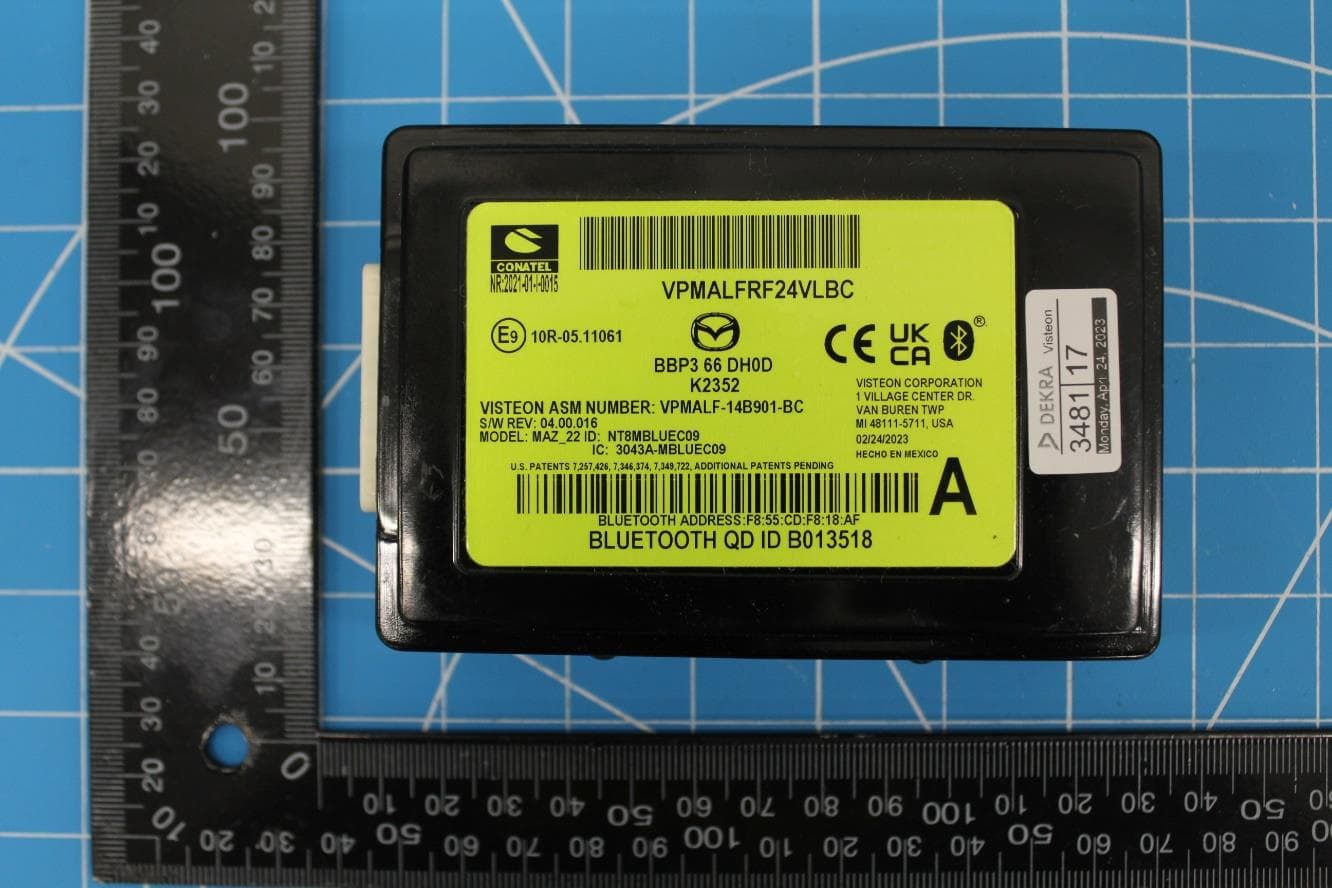
NT8-MAZ22HFT
Feb 15, 2024Bluetooth Telematics Device
Equipment Class
DSS - Part 15 Spread Spectrum Transmitter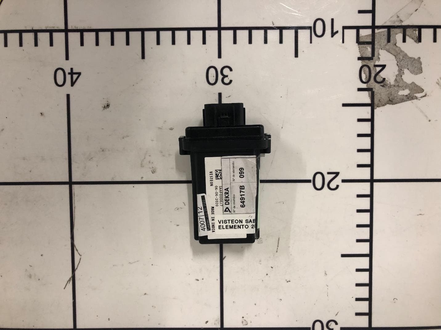
NT8-SAB01
Nov 01, 2023BT Unit
Equipment Class
DSS - Part 15 Spread Spectrum TransmitterNT8-SLA12
Jun 22, 2023Sense Line Assembly (SLA)
Equipment Class
JAB - Part 15 Class B Digital Device