NT8-14WCSCBWireless Charger for Vehicle
Visteon Corporation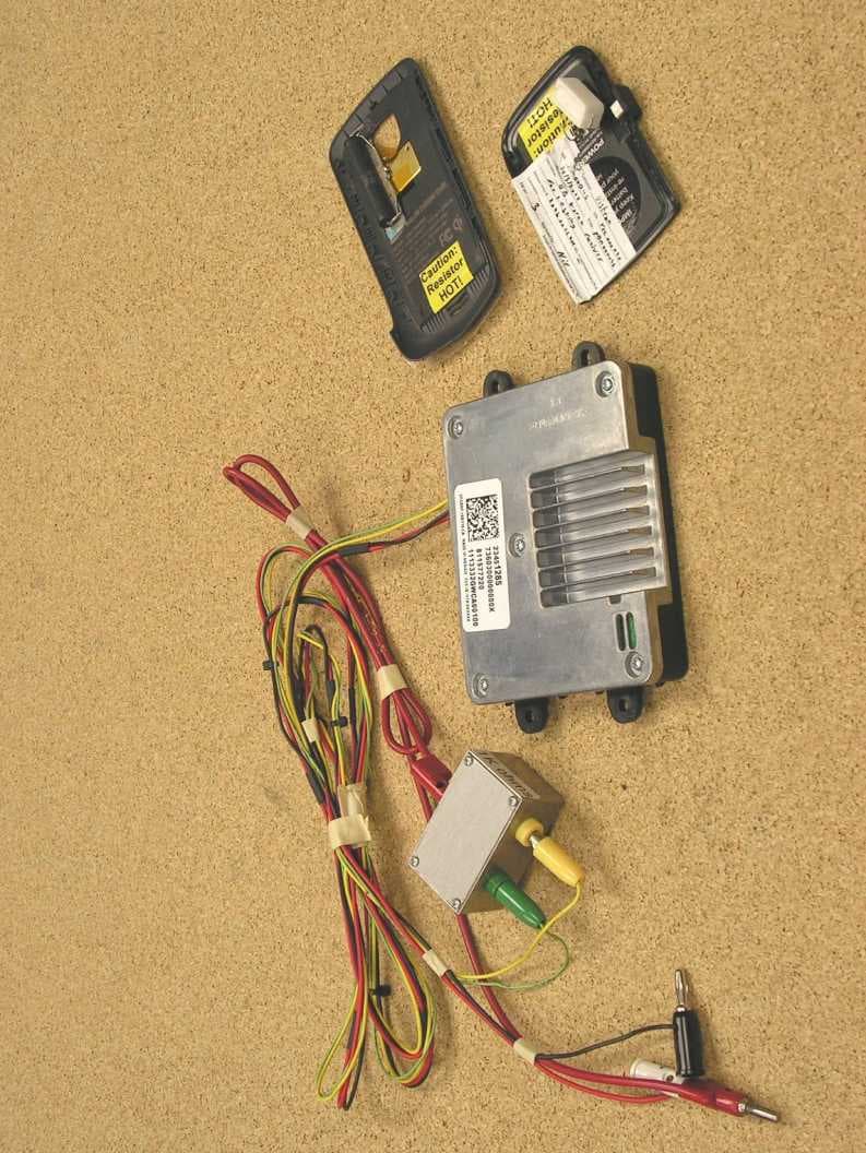
Click to zoom
Application Details
- Equipment Class
- 8CC - Part 18 Consumer Device
- Date of Grant
- Apr 29, 2014
- Application Purpose
- Original Equipment
- Date of Application
- Apr 03, 2014
- Equipment Note
- Wireless Charger for Vehicle
- Frequency Range
- 0.11000000 - 0.19000000
- Company
- Visteon Corporation
- Country
- United States
Documents & Files
Document Text
Text extracted from the exhibit documents filed with the FCC. Open a document above to read the original.
Cover Letter(s)
The University of Michigan Radiation Laboratory 3228 EECS Building Ann Arbor, Michigan 48109-2122 USA Tel: (734) 483-4211 Fax: (734) 647-2106 e-mail: [email protected] Attn.:Federal Communications Commission Equipment Approval Services P.O. Box 358315 Pittsburgh, PA 15251-5315 Re: Certification for Visteon Corporation VECAMF-12A661-AB FCC ID: NT8-14WCSCB Please find enclosed application materials for certification of Visteon Corporation VECAMF-12A661-AB. We tested it and found it to comply with CFR Title 47, Part 18.305. If there are any questions regarding the application or testing performed, please contact us at the above address or call (734) 483-4211, or e-mail [email protected]. Sincerely, Valdis V. Liepa The University of Michigan Radiation Laboratory 11
Cover Letter(s)
The University of Michigan Radiation Laboratory 3228 EECS Building Ann Arbor, Michigan 48109-2122 USA Tel: (734) 483-4211 Fax: (734) 647-2106 e-mail: [email protected] Re: Certification for Visteon Corporation FCC ID: NT8-14WCSCB IC: 3043A-14WCSCB REQUEST FOR CONFIDENTIALITY Pursuant to USA FCC 47 CRF 0.457(d) and 0.459 and Canada IC RSP-100, Section 10, Visteon Corporationrequests that a part of the subject application be held confidential. Visteon Corporation has spent substantial effort in developing this product and it is one of the first of its kind in industry. Having the subject information easily available to ”competition” would negate the advantage they have achieved by developing this product. Not protecting the details of the design will result in financial hardship. Exhibit Conf. TypeRational Exh 04 - Block DiagramPermanentIncludes proprietary internal oscillator frequency information. Exh 05 - SchematicsPermanentIncludes proprietary design information Exh 10 - BOM + PlacementPermanentIncludes proprietary design information Permanent Confidentiality:Visteon Corporation requests that any exhibits listed above as permanently confidential be permanently withheld from public review. Short-Term Confidentiality (FCC Only):Visteon Corporation requests that any exhibits selected above as short term confidential be withheld from public view for a period of 45 days from the date of the Grant of Equipment Authorization and prior to marketing. If there are any questions regarding the application or testing performed, please contact us at the above address or call (734) 483-4211, or e-mail [email protected]. Sincerely, Valdis V. Liepa The University of Michigan Radiation Laboratory 10
Operational Description
Visteon Wireless Charging System (WCS) Product Description The device being submitted, the Wireless Charging System (WCS) is a transmitter base designed to be used as an OEM installed wireless charger in a motor vehicle and uses magnetic inductive coupling to transfer energy from itself to a compatible, portable receiving device, such as a cellular phone. The transmitting device is based upon the Powermat Dual Mode wireless charging consumer product, but will work with both Powermat and WPC (Wireless Power Consortium) compliant receivers. The receiver is a passive transponder that does not produce power on its own. The WCS is designed to work in close proximity to the receiving device (7 mm gap between coils and 12 mm offset between coil centers). The gap between transmitter and receiver coils will be occupied by housing or vehicle plastic material. The Wireless Charging System (WCS) charges a consumer device by using an electromagnetic field to transfer energy. By varying the current in the primary induction coil in the WCS, an alternating electromagnetic field is generated from within a charging base station. A second induction coil in the receiver of the handheld device takes power from the electromagnetic field and converts it back into electrical current to charge the device battery. The two induction coils in proximity combine to form an electrical transformer. Load detection is performed via a low amplitude pulse. The transmitter primary coil voltage/current is monitored to detect a change in the amplitude, indicating the presence of an object in proximity to the charging surface. Once an object is detected, an identification burst of energy is radiated to charge the circuit in the receiver and a response is queried to determine if the object is a compatible device to be charged. Client registration is determined and established either by WPC protocol for WPC compliant devices, or by recognition of response signature from Powermat compatible devices. Communication is achieved by modulation of the reflected impedance by the receiver circuit. Upon confirmation of compatible object, charging commences until the device terminates the charging mode or is removed. Power transfer is controlled through the receiver monitoring the voltage across the load and sending control error values (WPC) or power change requests (PM). Upon confirmation of compatible object, charging commences until the device terminates the charging mode or is removed. Power transfer is controlled through the receiver monitoring the voltage across the load and sending control error values (WPC) or power change requests (PM). The charging pad enters standby upon application of 12V input power and the absence of a device on the charging surface. The presence of a compatible device and input power will initiate charging mode. Charging completion is determined via an End of Charge message from the receiver to the transmitter. The receivers monitor the charge state via different methods/algorithms depending on WPC or Powermat architecture and OEM design. The charging power is variable, depending on the control point error message or power change request from the device.
RF Exposure Info
RF Exposure / SAR / Health Hazard Statement Regulations: According to USA CFR 47 Part 15 §1.1307 (b)(1), systems operating under the provisions of this section shall be operated in a manner that ensures the public is not exposed to radio frequency energy level in excess of the Commission’s guideline. For Canada, IC RSS-102 sets out the requirements and measurement techniques used to evaluate radio frequency (RF) exposure compliance of radiocommunication apparatus designed to be used within the vicinity of the human body. MPE/SAR Testing Requirements: Per FCC KDB 680106 D01 RF Exposure Wireless Charging Apps v02, Section 3, Paragraph 3, RF exposure evaluation of wireless charging pads should be conducted assuming a user separation distance of 10 cm. E and H-field strength measurements or numerical modeling may be used to demonstrate compliance. Measurements should be made from all sides and the top of the primary/client pair, with the 10 cm distance measured from the center of the probe(s) to the edge of the device. Emissions between 100 kHz to 300 kHz should be assessed versus the limits at 300 kHz in Table 1 of Section 1.1310: 614 V/m (175.8 dBuV/m) E-field and 1.63 A/m (124.2 dBuA/m) H-field in a 30 minute averaging time. Per IC RSS-102, emissions between 3 kHz and 1 MHz for use in an uncontrolled environment should be assessed versus the limits in Table 4.2 of Section 4 : 280 V/m (169 dBuV/m) E-field and 2.19A/m (126.8 dBuA/m) H-field in a 6 minute averaging time. Procedure: Since the EUT transmits continuously while charging, the instantaneous measured field values are thus reported in demonstrating compliance.The highest field strengths measured at 0 cm separation from the EUT (as requested by the FCC) in both charging modes on all exposed sides are reported below. Measurements are made using UM OSHA's ETS-Lindgren / Holaday HI-3603 VLF Field Survey meter (UMHI3603), set in max-hold, rotated through three axes, and kept in contact with the surface of the EUT along each face.
Test Report
Date of Issue: April 4, 2014Prepared For: Visteon CorporationTest Report No.: 417124-667r2 The University of Michigan Radiation Laboratory 3228 EECS Building Ann Arbor, Michigan 48109-2122 USA Tel: (734) 483-4211 Fax: (734) 647-2106 e-mail: [email protected] Testing of Electromagnetic Emissions per USA: CFR Title 47, Part 18.305 Canada: ICES-001 are herein reported for Visteon Corporation VECAMF-12A661-AB Test Report No.: 417124-667r2 Copyright c ©2014 Applicant/Provider: Visteon Corporation One Village Center Drive, Van Buren Township Michigan 483111 USA Phone: +1 (734) 710-7137, Fax: +1 (734) 736-5612 Contact Person: Terry SanSouci; [email protected] Report by: Report Date of Issue: April 4, 2014 Valdis V. Liepa, Ph.D. Results of testing completed on (or before) April 4, 2014 are as follows. Emissions:The transmitter intentional emissionsCOMPLYwith the regulatory limit(s) by no less than 24.4 dB. Transmit chain spurious harmonic emissionsCOMPLYby no less than 13.5 dB. The University of Michigan Radiation Laboratory, 3228 EECS Building, Ann Arbor, Michigan 48109-2122 USAPage 1 of 15 Date of Issue: April 4, 2014Prepared For: Visteon CorporationTest Report No.: 417124-667r2 Contents 1 Test Specifications, General Procedures, and Location3 1.1 Test Specification and General Procedures . . . . . . . . . . . . . . . . . . . . . . . . . . . . . . . . . .3 1.2 Test Location and Equipment Used . . . . . . . . . . . . . . . . . . . . . . . . . . . . . . . . . . . . . .4 2 Configuration and Identification of the Equipment Under Test5 2.1 Description and Declarations . . . . . . . . . . . . . . . . . . . . . . . . . . . . . . . . . . . . . . . . .5 2.1.1EUT Configuration . . . . . . . . . . . . . . . . . . . . . . . . . . . . . . . . . . . . . . . . . . .5 2.1.2Modes of Operation . . . . . . . . . . . . . . . . . . . . . . . . . . . . . . . . . . . . . . . . . .5 2.1.3Variants . . . . . . . . . . . . . . . . . . . . . . . . . . . . . . . . . . . . . . . . . . . . . . . . .6 2.1.4Test Samples . . . . . . . . . . . . . . . . . . . . . . . . . . . . . . . . . . . . . . . . . . . . . .6 2.1.5Functional Exerciser . . . . . . . . . . . . . . . . . . . . . . . . . . . . . . . . . . . . . . . . . .6 2.1.6Modifications Made . . . . . . . . . . . . . . . . . . . . . . . . . . . . . . . . . . . . . . . . . .6 2.1.7Production Intent . . . . . . . . . . . . . . . . . . . . . . . . . . . . . . . . . . . . . . . . . . .6 2.1.8Declared Exemptions and Additional Product Notes . . . . . . . . . . . . . . . . . . . . . . . .6 3 Emissions7 3.1 General Test Procedures . . . . . . . . . . . . . . . . . . . . . . . . . . . . . . . . . . . . . . . . . . . .7 3.1.1Radiated Test Setup and Procedures . . . . . . . . . . . . . . . . . . . . . . . . . . . . . . . . .7 3.1.2Conducted Emissions Test Setup and Procedures . . . . . . . . . . . . . . . . . . . . . . . . . .9 3.1.3Power Supply Variation . . . . . . . . . . . . . . . . . . . . . . . . . . . . . . . . . . . . . . . .9 3.2 Intentional Emissions . . . . . . . . . . . . . . . . . . . . . . . . . . . . . . . . . . . . . . . . . . . . . . 10 3.2.1Fundamental Emission Pulsed Operation . . . . . . . . . . . . . . . . . . . . . . . . . . . . . . 10 3.2.2Fundamental Emission Bandwidth . . . . . . . . . . . . . . . . . . . . . . . . . . . . . . . . . . 11 3.2.3Fundamental Emission . . . . . . . . . . . . . . . . . . . . . . . . . . . . . . . . . . . . . . . . . 12 3.3 Unintentional Emissions . . . . . . . . . . . . . . . . . . . . . . . . . . . . . . . . . . . . . . . . . . . . 13 3.3.1Transmit Chain Spurious Emissions . . . . . . . . . . . . . . . . . . . . . . . . . . . . . . . . . 13 List of Tables 1The University of Michigan Radiation Laboratory Equipment List.. . . . . . . . . . . . . . . . . . .4 2EUT Declarations. . . . . . . . . . . . . . . . . . . . . . . . . . . . . . . . . . . . . . . . . . . . . . . .5 3Pulsed Emission Characteristics (Duty Cycle). . . . . . . . . . . . . . . . . . . . . . . . . . . . . . . . 10 4Intentional Emission Bandwidth.. . . . . . . . . . . . . . . . . . . . . . . . . . . . . . . . . . . . . . 11 5Fundamental Radiated Emissions. . . . . . . . . . . . . . . . . . . . . . . . . . . . . . . . . . . . . . . 12 6Transmit Chain Spurious Emissions. . . . . . . . . . . . . . . . . . . . . . . . . . . . . . . . . . . . . . 14 6Transmit Chain Spurious Emissions. . . . . . . . . . . . . . . . . . . . . . . . . . . . . . . . . . . . . . 15 List of Figures 1Photos of EUT.. . . . . . . . . . . . . . . . . . . . . . . . . . . . . . . . . . . . . . . . . . . . . . . .5 2EUT Test Configuration Diagram. . . . . . . . . . . . . . . . . . . . . . . . . . . . . . . . . . . . . . .6 3Radiated Emissions Diagram of the EUT. . . . . . . . . . . . . . . . . . . . . . . . . . . . . . . . . . .7 4Radiated Emissions Test Setup Photograph(s). . . . . . . . . . . . . . . . . . . . . . . . . . . . . . . .8 5Intentional Emission Bandwidth.. . . . . . . . . . . . . . . . . . . . . . . . . . . . . . . . . . . . . . 11 The University of Michigan Radiation Laboratory, 3228 EECS Building, Ann Arbor, Michigan 48109-2122 USAPage 2 of 15 Date of Issue: April 4, 2014Prepared For: Visteon CorporationTest Report No.: 417124-667r2 1 Test Specifications, General Procedures, and Location 1.1 Test Specification and General Procedures The ultimate goal of Visteon Corporation is to demonstrate that the Equipment Under Test (EUT) complies with the Rules and/or Directives below. Detailed in this report are the results of testing the Visteon Corporation VECAMF- 12A661-AB for compliance to: Country/RegionRules or DirectiveReferenced Section(s) United StatesCode of Federal RegulationsCFR Title 47, Part 18.305 CanadaIndustry CanadaICES-001 In association with the rules and directives outlined above, the following specifications and procedures are fol- lowed herein. ANSI C63.4-2003 ”Methods of Measurement of Radio-Noise Emissions from Low-Voltage Electri- cal and Electronic Equipment in the Rang…
Text truncated - open the document above for the full version.
Contact Information
Applicant
Terry SanSouci(Product Assurance Test Engineer)
Technical Contact
University of Michigan Radiation LabValdis V. Liepa
[email protected]734-483-4211
3228 EECS Building · Ann Arbor · United States
Test Firm
University of MichiganValdis Liepa
Technical Specifications
| # | Rule Parts | Frequency Range | Power Output |
|---|---|---|---|
| 1 | 18 | 0.11 MHz - 0.19 MHz | - |
Other Applications from Visteon Corporation
NT8-BPCMFXE
Feb 20, 2026Battery Pack Control Module (BPCM)
Equipment Class
JAB - Part 15 Class B Digital DeviceNT8-BPCMSW
Dec 02, 2024Battery Pack Control Module (BPCM)
Equipment Class
DTS - Digital Transmission System
NT8-MAZ22HFT
Feb 15, 2024Bluetooth Telematics Device
Equipment Class
DSS - Part 15 Spread Spectrum Transmitter
NT8-SAB01
Nov 01, 2023BT Unit
Equipment Class
DSS - Part 15 Spread Spectrum TransmitterNT8-SLA12
Jun 22, 2023Sense Line Assembly (SLA)
Equipment Class
JAB - Part 15 Class B Digital Device