NT8-156071U3FXCVRPassive Anti-Theft System
Visteon Corporation
Click to zoom
Application Details
- Equipment Class
- DSR - Part 15 Remote Control/Security Device Transceiver
- Date of Grant
- Jul 09, 2000
- Application Purpose
- Original Equipment
- Date of Application
- Jun 04, 2000
- Equipment Note
- Passive Anti-Theft System
- Frequency Range
- 0.12300000 - 0.13400000
- Company
- Visteon Corporation
- Country
- United States
Documents & Files
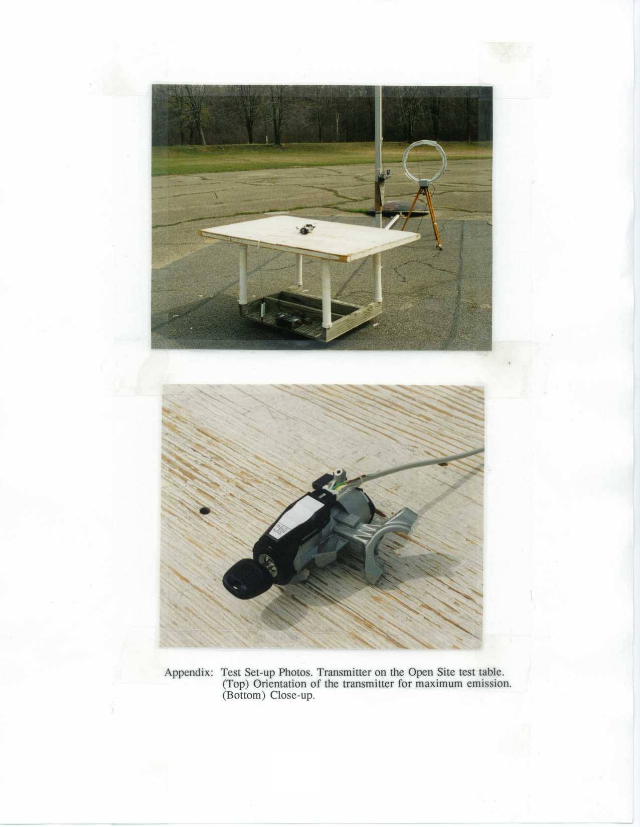
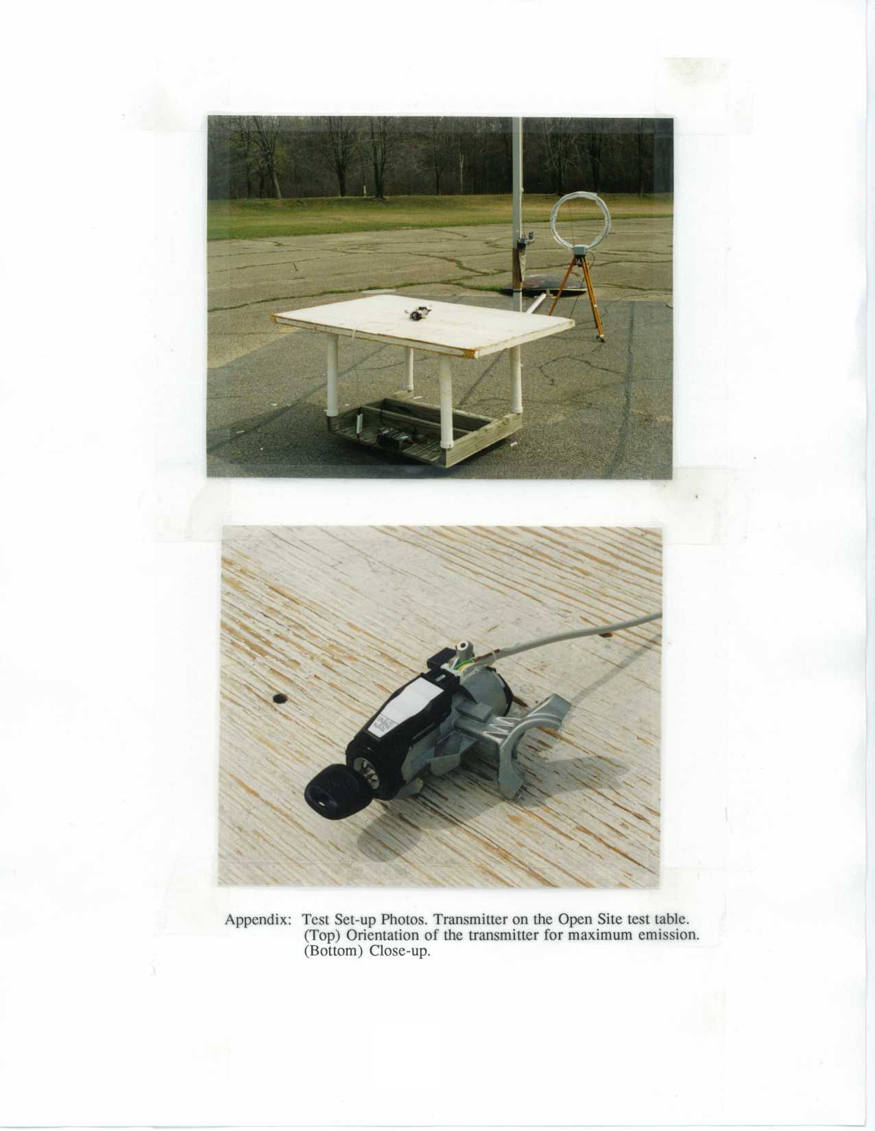
Document Text
Text extracted from the exhibit documents filed with the FCC. Open a document above to read the original.
Operational Description
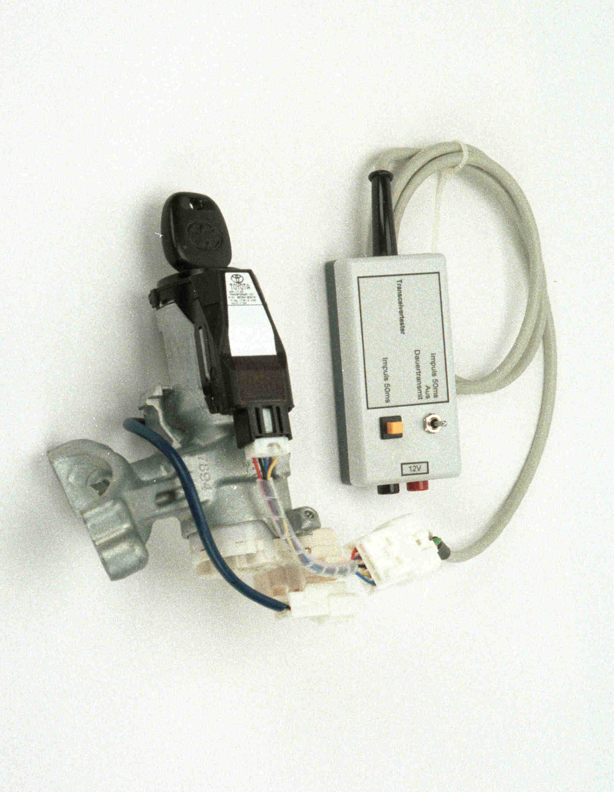
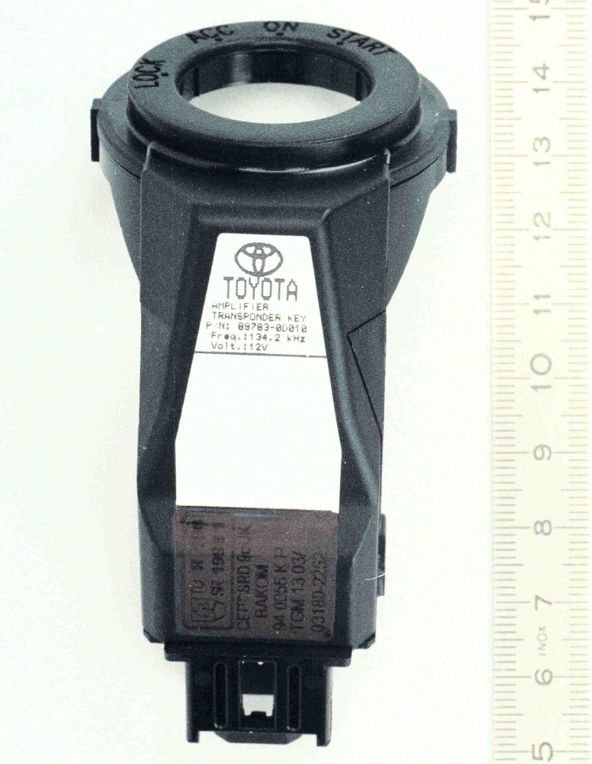
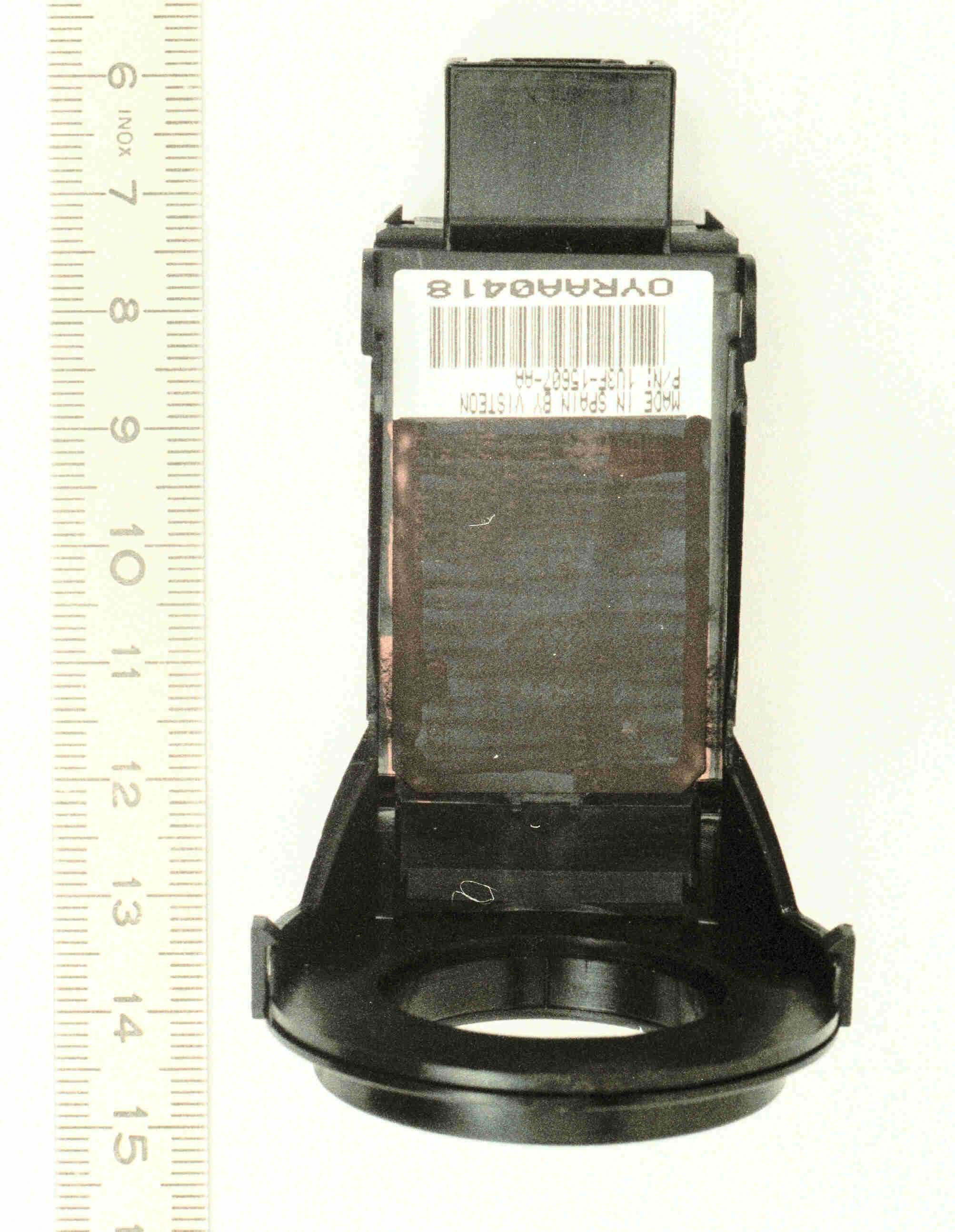
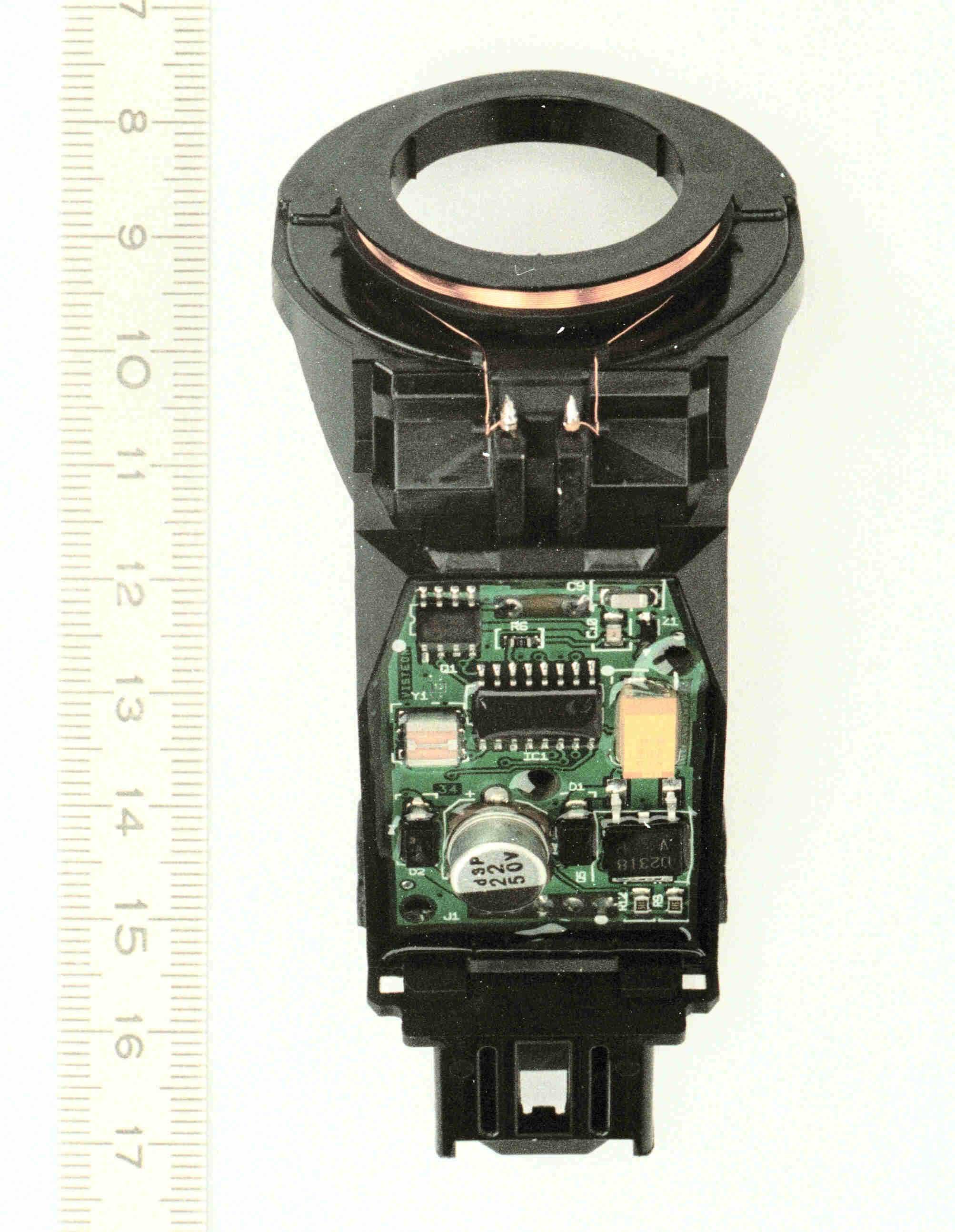
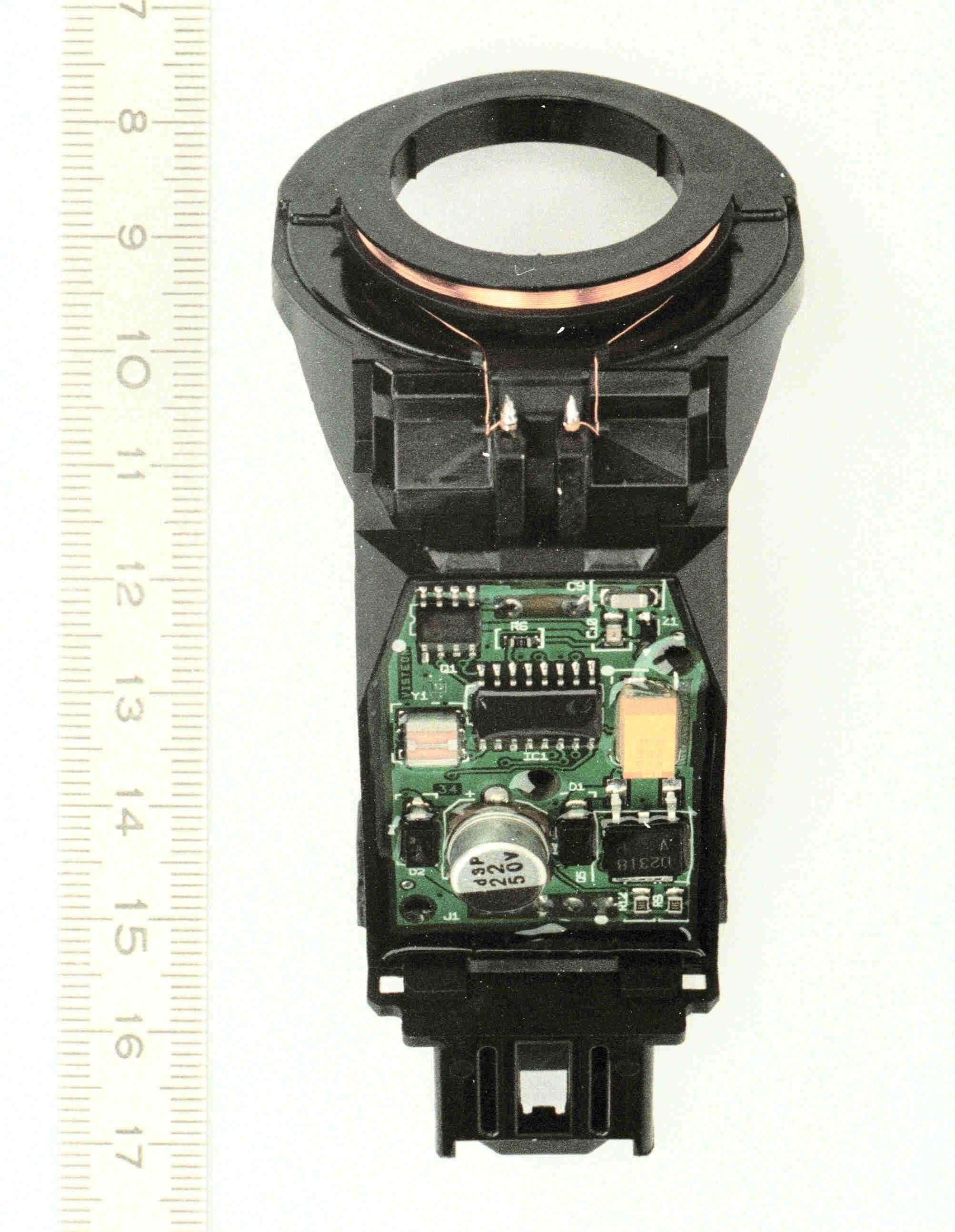
184N JA Function description 27.03.00 Page 1 of 6 J. von Berg 1. 184N Transceiver Function Description: The 184N transceiver is the interface device between an ECU (Electronic Control Unit) and a TIRIS transponder. The ECU interrogates the transponder by first initiating a charge phase. The charge phase generates an electromagnetic field around the antenna coil from which the transponder will accumulate and store energy on its internal charge capacitor. This energy is used to power the transponder in the Read Phase where it sends back a total of 128 bits. In the Read Phase, the data read is validated against a known value and depending on match, the vehicle is enabled. AMP E/G ECU COIL TXCT CODE RXCK B+ B+ E/G ECUR RELAY GNDGND Figure 1 Transceiver to ECU connection 1.1. Charge Phase: The ECU initiates the charge phase by simply pulling the TXCT signal high to +5V nom.. As long as the TXCT stays at a high level, the transceiver will continuously charge the transponder. When the charge time expires (typically about 50 ms), the ECU will than pull the TXCT line low and continue into the read phase. In the charge phase, the ECU is immune to any activity on both RXCK and CODE line. 1.2. Read Phase: The read phase consists of three sub-phases, the waiting time, the watching time and the data processing time. 1.2.1.Waiting: Upon pulling the TXCT line low, the ECU must enter a wait state of not less than 1ms and no more than 1.5 ms after the falling edge of TXCT. In this period of time, no valid data on CODE is present and the ECU must not respond to any transition on CODE or RXCK lines. 1.2.2.Receiving: After the Waiting state, the transponder sends a FSK signal back to the transceiver. The two nominal frequencies are 123,2 kHz representing a logical "1" and 134,2 kHz representing a logical "0". One bit consists of 16 periods of the corresponding frequency. This signal is picked-up by the coil then amplified and decoded. This decoded information is sent to the ECU, using a Synchronous Serial Interface. The ECU starts to check the (data) CODE signal to detect the first low to high transition of the Start Byte (7E). The (clock) RXCK signal is synchronous to the CODE after the first rising edge of CODE. After this event the data on CODE is valid during a low level of RXCK. Since the first transition of the CODE signal is the second bit of the start byte, the first bit (LSB) has to be stuffed with a "0". See Figure 3 The Receiving state must be limited depending on the selected Waiting state. The sum of Waiting time and Receiving time should be equal or less than 20 ms. This is the time in which data on CODE can be expected. 184N JA Function description 27.03.00 Page 2 of 6 J. von Berg 1.2.3.Data Processing : The data sent by the transponder contains16 Bytes, see Figure 5. The evaluation takes place in the ECU. After all bytes are read and the BCC matches the calculated CRC (specified in the CCIT algorithm) and after validation of the identification data, the ECU enables the starting sequence. 184N JA Function description 27.03.00 Page 3 of 6 J. von Berg 2. I/O Timing TXCT RXCK CODE Start of Cycle End of Cycle Charge Time Read Time Figure 2 Normal Transmit/Receive Cycle Note: the state of RXCK and CODE is not defined before and after the complete cycle. 184N JA Function description 27.03.00 Page 4 of 6 J. von Berg TXCT RXCK CODE Figure 3 Synchronization of RXCK to CODE 184N JA Function description 27.03.00 Page 5 of 6 J. von Berg TXCT RXCK CODE t setup t valid t hold Figure 4 CODE setup and hold times during normal transmission 184N JA Function description 27.03.00 Page 6 of 6 J. von Berg 3. Serial Synchronous Communication Interface Protocol Pre Bytes Byte Byte Byte Byte Byte Byte Byte 123456789101112131415 Byte Byte Byte Byte Byte Byte Byte ByteByte 0 7Eh Start BCC Data End o f transm charge time Approx. 2ms after falli edge of TXC 7Eh StopIdentification dataEnd Bytes 010101 10 LSB MSB Note: Data bits are not symetr Bit "0" is shorter t the number of period Logic 1/134,2 kHz = μs Logic 1/123,2 kHz = μs Serial data to ECU Byte value AAh FSK data transmitted by transponder Figure 5 64-bit Read/Only Transponder Read Data Format
Parts List/Tune Up Info
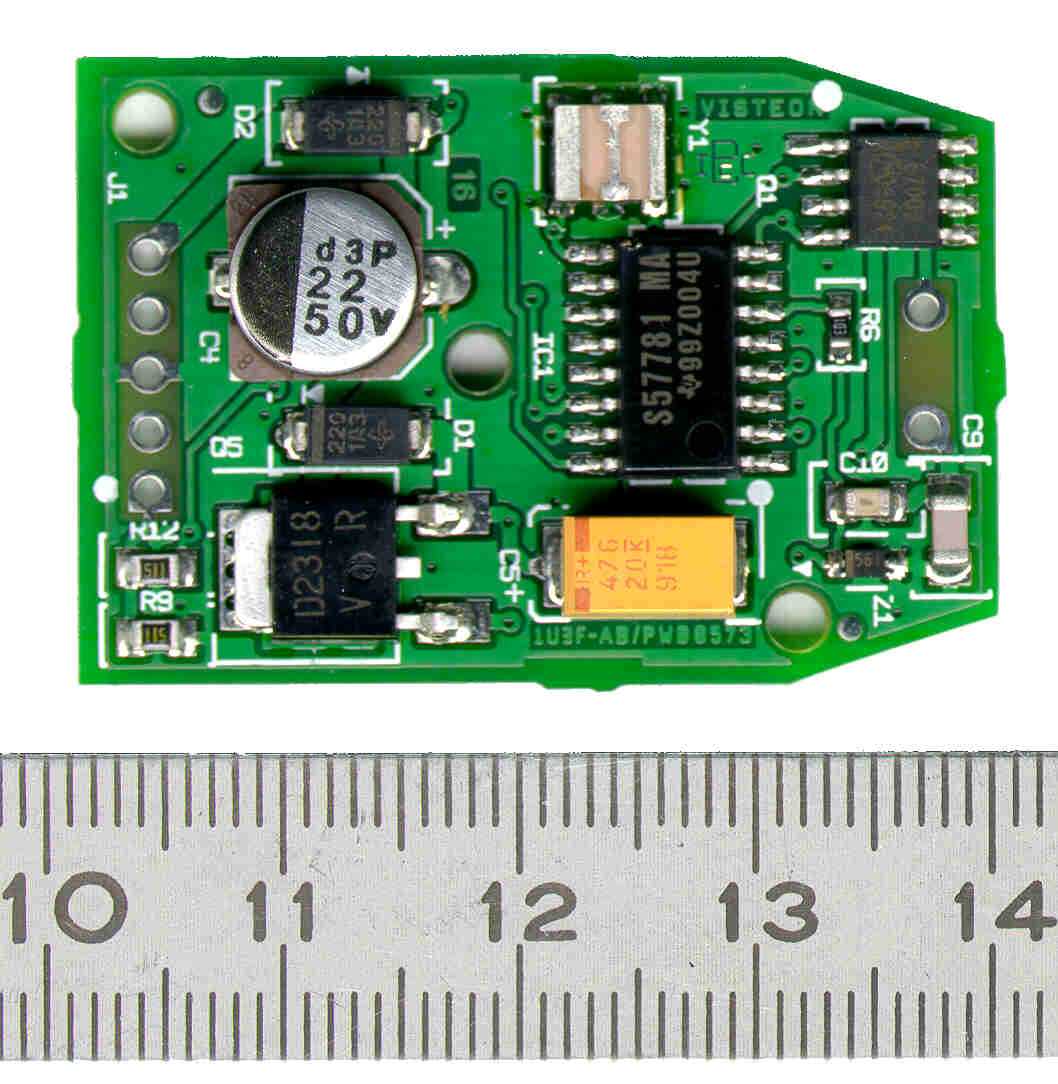
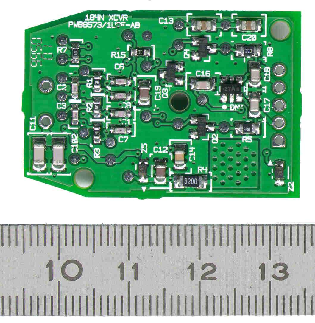
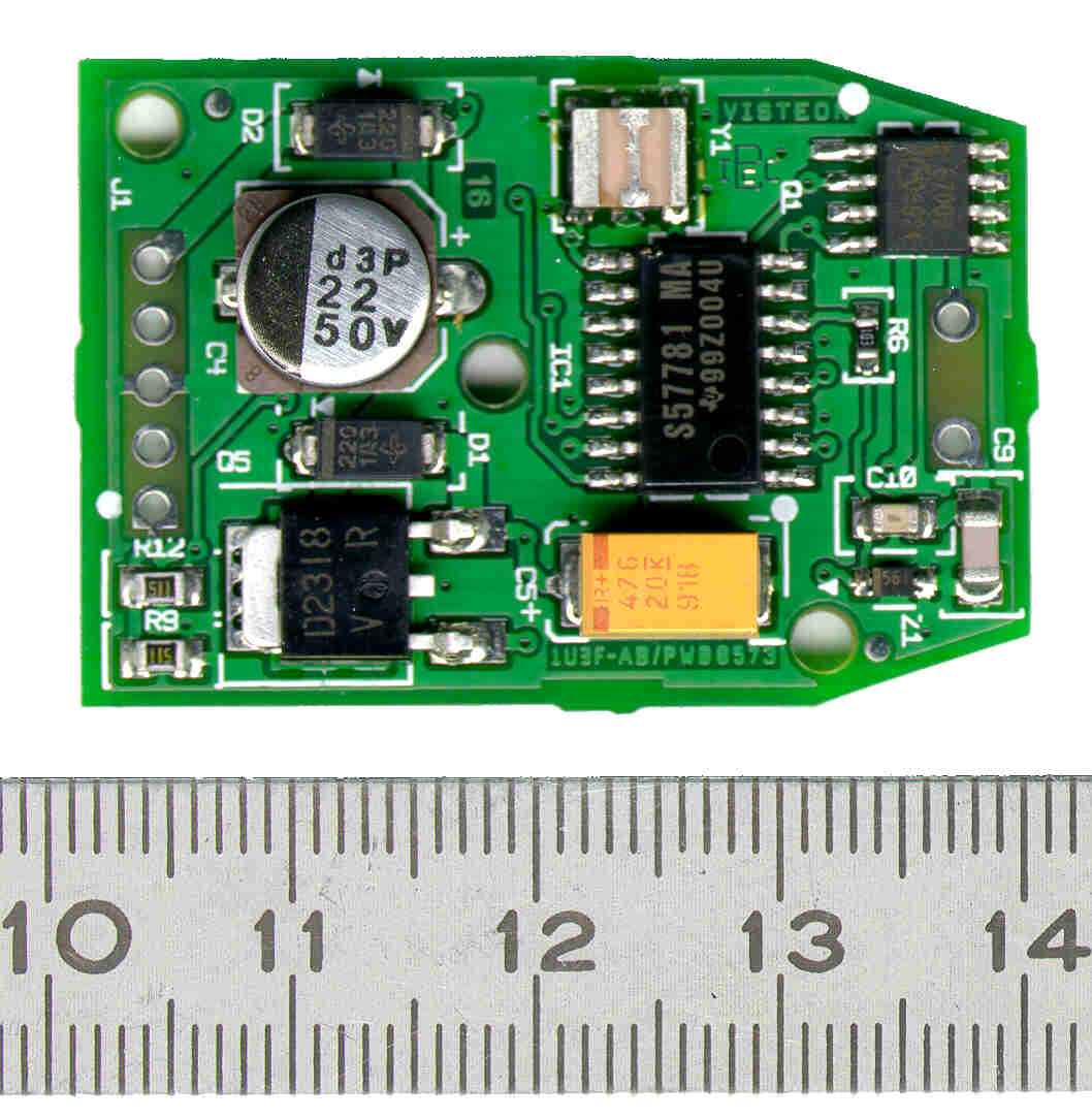
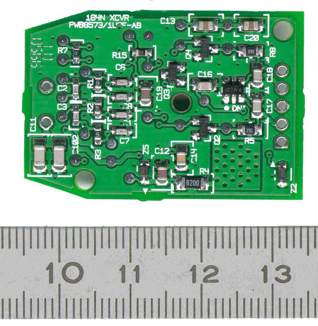
1U3F-15607-A Bill of Material DescriptionSymbolQuantity INTRFC IC, TMS57781NS-MA, SOIC, 16IC11 RES,TF,10KOhms,5%,63mW,0603R61 RES,TF,1MOhms,5%,63mW,0603R11 RES,TF,1MOhms,5%,63mW,0603R21 RES,TF,1MOhms,5%,63mW,0603R31 RES,TF,220Ohms,5%,63mW,0603R71 RES,TF,33KOhms,5%,63mW,0603R151 RES,TF,39Ohms,5%,100mW,0805R51 RES,TF,39Ohms,5%,100mW,0805R81 RES,TF,510Ohms,10%,100mW,0805R91 RES,TF,510Ohms,10%,100mW,0805R121 RES,TF,820Ohms,5%,125mW,1206R41 CAP,CERM,1nF,20%,100V,0805C161 CAP,CERM,1nF,20%,100V,0805C171 CAP,CERM,1nF,20%,100V,0805C181 CAP,CERM,10nF,20%,100V,0805C121 CAP,CERM,10nF,20%,100V,0805C191 CAP,CERM,100nF,10%,50V,0805C141 CAP,CERM,22nF,10%,100V,0805C131 CAP,CERM,22nF,10%,100V,0805C201 CAP,CERM,3.9nF,2%,50V,1206C91 CAP,CERM,3.9nF,2%,50V,1206C111 CAP,CERM,3.9nF,2%,50V,1206C1021 CAP,CERM,68pF,5%,50V,0603C11 CAP,CERM,68pF,5%,50V,0603C21 CAP,CERM,68pF,5%,50V,0603C31 CAP,CERM,68pF,5%,50V,0603C61 CAP,CERM,68pF,5%,50V,0603C71 CAP,CERM,68pF,5%,50V,0603C81 CAP,CERM,680pF,5%,100V,0805C101 CAP,ALUM,22uF,20%,50V,SMDC41 CAP,TANT,47uF,10%,20V,TA-XC51 DIO,VSUP,27V,5%,SC-59,MMQA27VT1DN11 DIO,RECT,400V,1A,GF-1,GF1-GD11 DIO,RECT,400V,1A,GF-1,GF1-GD21 DIO,ZENR,5.6V,2%,200mW,SOD323,RD5.Z51 DIO,ZENR,5.6V,5%,200mW,SOD323,RD5.Z11 DIO,ZENR,6.8V,5%,200mW,SOD323,RD6.Z21 TRANS,PBIP,NPN,3A,1W,D-PAK,2SD2318Q51 TRANS,BRES,NPN,100mA,200mW,SOT-23,Q21 TRANS,BRES,NPN,100mA,200mW,SOT-23,Q31 TRANS,BRES,NPN,100mA,200mW,SOT-23,Q41 TRANS,PMOS,3A,2W,SO-8,MMDF2C03EQ11 RESON,RCERM,17.12MHz,CSTCS_MXY11 IMMOBIL. COVER-PWB1 PLATE-IDENT.LABEL 167W1 PLATE-RTA LABEL 167W1 COIL CONNECTOR HSG.1
Parts List/Tune Up Info
1U3F-15607-A Bill of Material DescriptionSymbolQuantity INTRFC IC, TMS57781NS-MA, SOIC, 16IC11 RES,TF,10KOhms,5%,63mW,0603R61 RES,TF,1MOhms,5%,63mW,0603R11 RES,TF,1MOhms,5%,63mW,0603R21 RES,TF,1MOhms,5%,63mW,0603R31 RES,TF,220Ohms,5%,63mW,0603R71 RES,TF,33KOhms,5%,63mW,0603R151 RES,TF,39Ohms,5%,100mW,0805R51 RES,TF,39Ohms,5%,100mW,0805R81 RES,TF,510Ohms,10%,100mW,0805R91 RES,TF,510Ohms,10%,100mW,0805R121 RES,TF,820Ohms,5%,125mW,1206R41 CAP,CERM,1nF,20%,100V,0805C161 CAP,CERM,1nF,20%,100V,0805C171 CAP,CERM,1nF,20%,100V,0805C181 CAP,CERM,10nF,20%,100V,0805C121 CAP,CERM,10nF,20%,100V,0805C191 CAP,CERM,100nF,10%,50V,0805C141 CAP,CERM,22nF,10%,100V,0805C131 CAP,CERM,22nF,10%,100V,0805C201 CAP,CERM,3.9nF,2%,50V,1206C91 CAP,CERM,3.9nF,2%,50V,1206C111 CAP,CERM,3.9nF,2%,50V,1206C1021 CAP,CERM,68pF,5%,50V,0603C11 CAP,CERM,68pF,5%,50V,0603C21 CAP,CERM,68pF,5%,50V,0603C31 CAP,CERM,68pF,5%,50V,0603C61 CAP,CERM,68pF,5%,50V,0603C71 CAP,CERM,68pF,5%,50V,0603C81 CAP,CERM,680pF,5%,100V,0805C101 CAP,ALUM,22uF,20%,50V,SMDC41 CAP,TANT,47uF,10%,20V,TA-XC51 DIO,VSUP,27V,5%,SC-59,MMQA27VT1DN11 DIO,RECT,400V,1A,GF-1,GF1-GD11 DIO,RECT,400V,1A,GF-1,GF1-GD21 DIO,ZENR,5.6V,2%,200mW,SOD323,RD5.Z51 DIO,ZENR,5.6V,5%,200mW,SOD323,RD5.Z11 DIO,ZENR,6.8V,5%,200mW,SOD323,RD6.Z21 TRANS,PBIP,NPN,3A,1W,D-PAK,2SD2318Q51 TRANS,BRES,NPN,100mA,200mW,SOT-23,Q21 TRANS,BRES,NPN,100mA,200mW,SOT-23,Q31 TRANS,BRES,NPN,100mA,200mW,SOT-23,Q41 TRANS,PMOS,3A,2W,SO-8,MMDF2C03EQ11 RESON,RCERM,17.12MHz,CSTCS_MXY11 IMMOBIL. COVER-PWB1 PLATE-IDENT.LABEL 167W1 PLATE-RTA LABEL 167W1 COIL CONNECTOR HSG.1
Contact Information
Applicant
Terry SanSouci(Product Assurance Test Engineer)
Technical Contact
University of Michigan/EECSValdis V Liepa
[email protected]734-483-4211
1301 Beal Avenue · Ann Arbor, Michigan · United States
Non-Technical Contact
University of Michigan/EECSValdis V Liepa
[email protected]734-483-4211
Test Firm
University of MichiganValdis Liepa
Technical Specifications
| # | Rule Parts | Frequency Range | Power Output |
|---|---|---|---|
| 1 | 15C | 0.123 MHz - 0.134 MHz | - |
Other Applications from Visteon Corporation
NT8-BPCMFXE
Feb 20, 2026Battery Pack Control Module (BPCM)
Equipment Class
JAB - Part 15 Class B Digital DeviceNT8-BPCMSW
Dec 02, 2024Battery Pack Control Module (BPCM)
Equipment Class
DTS - Digital Transmission System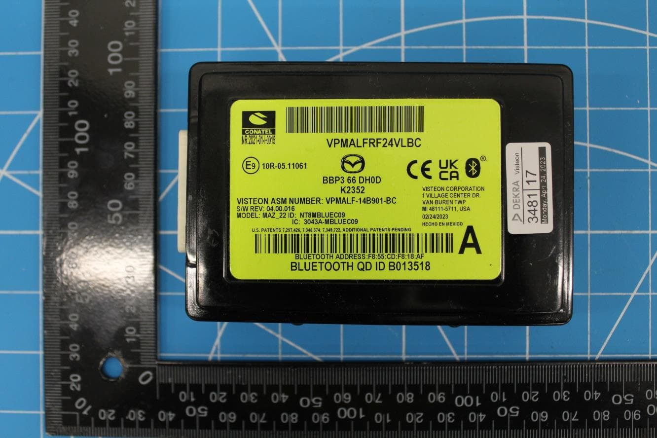
NT8-MAZ22HFT
Feb 15, 2024Bluetooth Telematics Device
Equipment Class
DSS - Part 15 Spread Spectrum Transmitter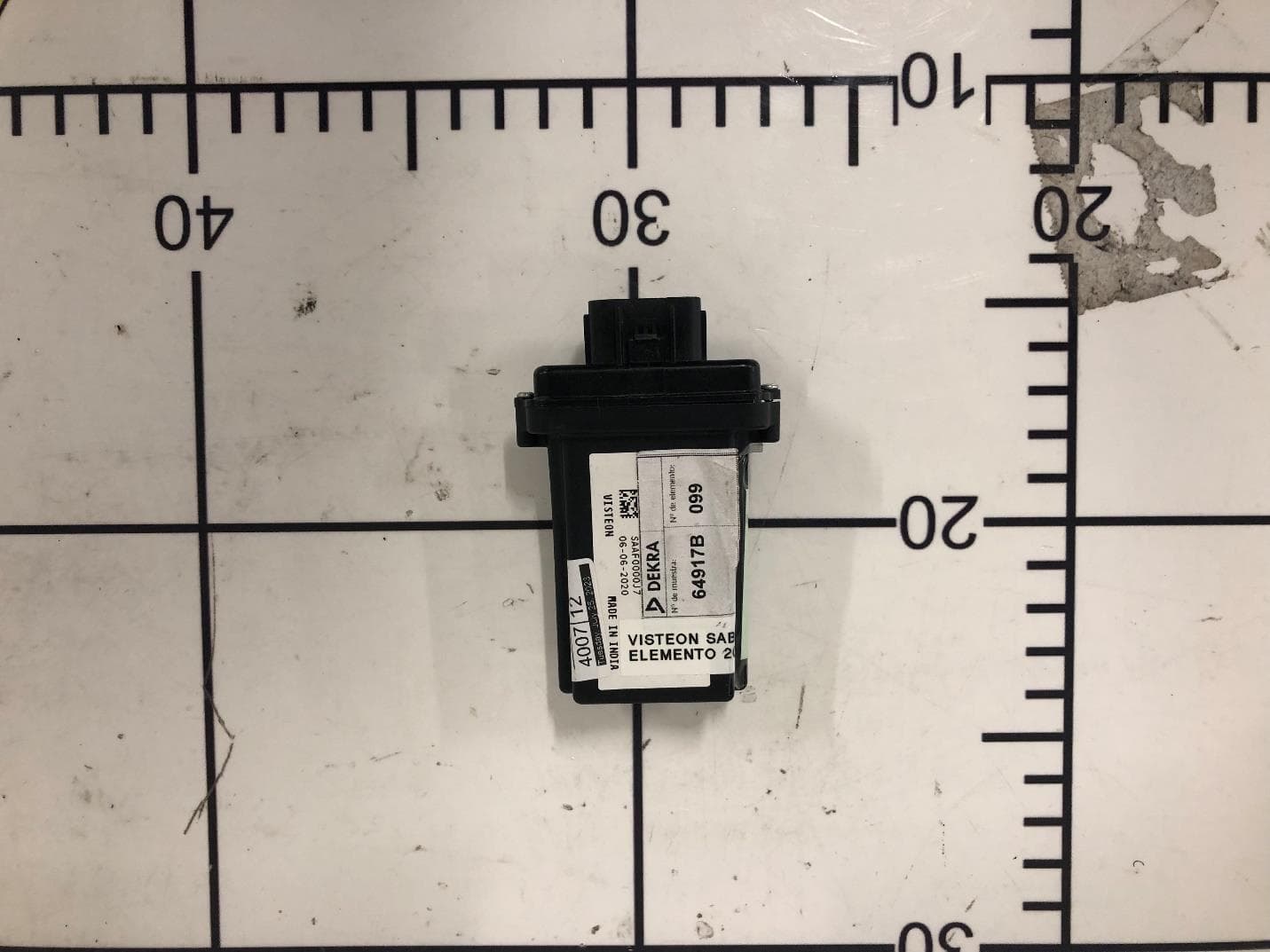
NT8-SAB01
Nov 01, 2023BT Unit
Equipment Class
DSS - Part 15 Spread Spectrum TransmitterNT8-SLA12
Jun 22, 2023Sense Line Assembly (SLA)
Equipment Class
JAB - Part 15 Class B Digital Device