NT8-315BUSTRAutomotive Receiver
Visteon Corporation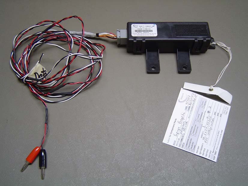
Click to zoom
Application Details
- Equipment Class
- CYY - Communications Receiver used w/Pt 15 Transmitter
- Date of Grant
- Oct 12, 2004
- Application Purpose
- Original Equipment
- Date of Application
- Oct 12, 2004
- Equipment Note
- Automotive Receiver
- Frequency Range
- 315.00000000 - 315.00000000
- Company
- Visteon Corporation
- Country
- United States
Documents & Files
Document Text
Text extracted from the exhibit documents filed with the FCC. Open a document above to read the original.
Block Diagram
Block Diagram Filter = 10.7MHz ceramic bpf Crystal = 10.178125MHz VCO Freq = 32 x Crystal = 315MHz + 10.7MHz = 325.7MHz
Cover Letter(s)
Re: Certification for Visteon BUSTER Receiver Model(s): 6W7T-14B207-A, 6W1T-14B207-A, 6W1T-15K602-A FCC ID: NT8-315BUSTR IC: 3043A-315BUSTR POWER OF ATTORNEY A letter granting Valdis V. Liepa the Power of Attorney is on file and can be provided when so requested. Re: Certification for Visteon BUSTER Receiver Model(s): 6W7T-14B207-A, 6W1T-14B207-A, 6W1T-15K602-A FCC ID: NT8-315BUSTR IC: 3043A-315BUSTR REQUEST FOR CONFIDENTIALITY Pursuant to 47 CRF 0.459, Visteon requests that a part of the subject application be held confidential. This comprises Exhibits (5) Schematics (10) Parts List (Part of Exhibit only) Visteon has spent substantial effort in developing this product and it is one of the first of its kind in industry. Having the subject information easily available to "competition" would negate the advantage they have achieved by developing this product. Not protecting the details of the design will result in financial hardship. If there are any questions regarding this request, please contact me at the above address or call 734-483-4211, fax 734-647-2106 or e-mail [email protected]. Sincerely, Valdis V. Liepa Research Scientist University of Michigan October 7, 2004 Re: Certification for Visteon BUSTER Receiver Model(s): 6W7T-14B207-A, 6W1T-14B207-A, 6W1T-15K602-A FCC ID: NT8-315BUSTR IC: 3043A-315BUSTR STATEMENT OF MODIFICATIONS There were no modifications made to the DUT by this test laboratory. (Also see Section 3.1 of the attached Test Report). _____________________ Valdis V. Liepa Research Scientist Re: Certification for Visteon BUSTER Receiver Model(s): 6W7T-14B207-A, 6W1T-14B207-A, 6W1T-15K602-A FCC ID: NT8-315BUSTR IC: 3043A-315BUSTR GENERAL PRODUCT INFORMATION The device, for which certification is pursued, has been designed by: Visteon Corporation 17000 Rotunda Drive Dearborn, MI 48121 Paul Schreiber Tel: (313) 755-0756 Fax: (313) 755-2810 It will be manufactured by: Visteon Corporation 17000 Rotunda Drive Dearborn, MI 48121 Paul Schreiber Tel: (313) 755-0756 Fax: (313) 755-2810 Canadian Contact: Ford Motor Company of Canada Limited The Canadian Road P.O. Box 2000 Oakville, Ontario, Canada L6J 5E4
Cover Letter(s)
October 11, 2004 RE: Visteon Corporation FCC ID: NT8-315BUSTR The following is in response to the comments made on the above referenced Application. 1) The EUT appears to include a daughter board. Please provide internal photographs of this board as well. Our apologies, the daughter board photos have been uploaded. 2) On the RSP form, one model includes a lower case k. Is this intentional? You are correct, the “k” should be a “K.” The documentation has been corrected and re- submitted. Thank you. 3) Please explain the difference between the 3 models covered in this application. There was a slight miscommunication at our end. The only difference between the models covered in this application is the plastic cases in which each model sits. All circuits and PCB boards are identical for all models. The test report has been modified to reflect this.
Cover Letter(s)
American Telecommunications Certification Body Inc. 6731 Whittier Ave, McLean, VA 22101 October 9, 2004 RE: Visteon Corporation FCC ID: NT8-315BUSTR After a review of the submitted information, I have a few comments on the above referenced Application. 1) The EUT appears to include a daughter board. Please provide internal photographs of this board as well. 2) On the RSP form, one model includes a lower case k. Is this intentional? 3) Please explain the difference between the 3 models covered in this application. Timothy R. Johnson Examining Engineer mailto: [email protected] The items indicated above must be submitted before processing can continue on the above referenced application. Failure to provide the requested information may result in application termination. Correspondence should be considered part of the permanent submission and may be viewed from the Internet after a Grant of Equipment Authorization is issued. Please do not respond to this correspondence using the email reply button. In order for your response to be processed expeditiously, you must submit your documents through the AmericanTCB.com website. Also, please note that partial responses increase processing time and should not be submitted. Any questions about the content of this correspondence should be directed to the sender.
ID Label/Location Info
FCC ID: NT8-315BUSTR IC: 3043A-315BUSTR
Operational Description
Functional Description The Buster radio frequency (RF) receiver is a compact single in-line package (SIP) designed for remote keyless entry (RKE) and tire pressure monitor system (TPMS) applications. An Infineon TDA5211 superheterodyne integrated circuit (IC) demodulates frequency shift keyed (FSK) data or 100% amplitude shift keyed (ASK a.k.a. on-off keyed (OOK)) data. Buster does not contain a microcontroller. Inputs to Buster are power, ground, enable, ASK/FSK* mode select, and the RF signal. When Buster is disabled, an internal polling circuit duty cycles the operating current down by at least half. The output from Buster is an open collector digital data signal that remains in the passive state when no detectable RF signal is present. When RF signal is present, the digital data signal becomes active. An external interrupt circuit to filter the digital data pulses is recommended to wake up the external host microcontroller. Upon wakeup, the microcontroller activates Buster enable and selects ASK or FSK mode to receive subsequent digitized demodulated data packets. The host microcontroller is responsible for decoding the data into commands.
Test Report
The University of Michigan Radiation Laboratory 3228 EECS Building Ann Arbor, MI 48109-2122 Tel: (734) 764-0500 Measured Radio Frequency Emissions From Visteon BUSTER Receiver Model(s): 6W7T-14B207-A, 6W1T-14B207-A, 6W1T-15K602-A Report No. 415031-223 October 5, 2004 Copyright © 2003 For: Visteon Corporation 17000 Rotunda Drive Dearborn, MI 48121 Contact: Ron Schuchard Tel: 313-755-6267 Fax: 313-755-2810 PO: Verbal Tests supervised by: Measurements made by: Report approved by: _____________________ Valdis V. Liepa Valdis V. Liepa Research Scientist Summary Tests for compliance with FCC Regulations Part 15, Subpart B, and Industry Canada RSS-210, were performed on Visteon Buster Receiver. This device is subject to the Rules and Regulations as a Receiver. As a Digital Device it is exempt, but such measurements were made to assess the receiver's overall emissions. In testing completed on September 9, 2004, the device tested in the worst case met the allowed FCC (Class B) specifications for radiated emissions by 11.5 dB (see p. 6). The conducted emissions tests do not apply, since the device is powered from a 12 VDC system. 2 1. Introduction Visteon Buster receiver was tested for compliance with FCC Regulations, Part 15, adopted under Docket 87-389, April 18, 1989, and with Industry Canada RSS-210, Issue 5, November, 2001. The tests were performed at the University of Michigan Radiation Laboratory Willow Run Test Range following the procedures described in ANSI C63.4-1992 "Methods of Measurement of Radio-Noise Emissions from Low-Voltage Electrical and Electronic Equipment in the Range of 9 kHz to 40 GHz". The Site description and attenuation characteristics of the Open Site facility are on file with FCC Laboratory, Columbia, Maryland (FCC Reg. No: 91050) and with Industry Canada, Ottawa, ON (File Ref. No: IC 2057). 2. Test Procedure and Equipment Used The pertinent test equipment commonly used in our facility for measurements is listed in Table 2.1 below. The middle column identifies the specific equipment used in these tests. Table 2.1 Test Equipment. Test Instrument Eqpt. Used Manufacturer/Model Spectrum Analyzer (0.1-1500 MHz) Hewlett-Packard, 182T/8558B Spectrum Analyzer (9kHz-22GHz) X Hewlett-Packard 8593A SN: 3107A01358 Spectrum Analyzer (9kHz-26GHz) X Hewlett-Packard 8593E, SN: 3412A01131 Spectrum Analyzer (9kHz-26GHz) Hewlett-Packard 8563E, SN: 3310A01174 Spectrum Analyzer (9kHz-40GHz) Hewlett-Packard 8564E, SN: 3745A01031 Power Meter Hewlett-Packard, 432A Power Meter Anritsu, ML4803A/MP Harmonic Mixer (26-40 GHz) Hewlett-Packard 11970A, SN: 3003A08327 Harmonic Mixer (40-60 GHz) Hewlett-Packard 11970U, SN: 2332A00500 Harmonic Mixer (75-110 GHz) Hewlett-Packard 11970W, SN: 2521A00179 Harmonic Mixer (140-220 GHz) Pacific Millimeter Prod., GMA, SN: 26 S-Band Std. Gain Horn S/A, Model SGH-2.6 C-Band Std. Gain Horn University of Michigan, NRL design XN-Band Std. Gain Horn University of Michigan, NRL design X-Band Std. Gain Horn S/A, Model 12-8.2 X-band horn (8.2- 12.4 GHz) Narda 640 X-band horn (8.2- 12.4 GHz) Scientific Atlanta , 12-8.2, SN: 730 K-band horn (18-26.5 GHz) FXR, Inc., K638KF Ka-band horn (26.5-40 GHz) FXR, Inc., U638A U-band horn (40-60 GHz) Custom Microwave, HO19 W-band horn(75-110 GHz) Custom Microwave, HO10 G-band horn (140-220 GHz) Custom Microwave, HO5R Bicone Antenna (30-250 MHz) X University of Michigan, RLBC-1 Bicone Antenna (200-1000 MHz) X University of Michigan, RLBC-2 Dipole Antenna Set (30-1000 MHz) X University of Michigan, RLDP-1,-2,-3 Dipole Antenna Set (30-1000 MHz) EMCO 2131C, SN: 992 Active Rod Antenna (30 Hz-50 MHz) EMCO 3301B, SN: 3223 Active Loop Antenna (30 Hz-50 MHz) EMCO 6502, SN:2855 Ridge-horn Antenna (300-5000 MHz) X University of Michigan Amplifier (5-1000 MHz) X Avantak, A11-1, A25-1S Amplifier (5-4500 MHz) X Avantak Amplifier (4.5-13 GHz) Avantek, AFT-12665 Amplifier (6-16 GHz) Trek Amplifier (16-26 GHz) Avantek LISN Box University of Michigan Signal Generator X Hewlett-Packard 8657B 3 3. Configuration and Identification of Device Under Test The DUT is a superheterodyne receiver, designed for onboard automobile TPM and security/convenience applications, and as such, it is powered from an automotive 12 VDC source. It is housed in a plastic case approximately 1 by 1 by 6 inches. Antenna is internal. For testing, a generic harness was provided by the manufacturer. The device VCO operates at 651.4 MHz, and the LO is 325.7 MHz. A 10.7 MHz crystal is used for IF reference. The DUT was designed by Visteon Corporation, 17000 Rotunda Drive, Dearborn, MI 48121. It is identified as: Visteon Corporation BUSTER Receiver Model(s): 6W7T-14B207-A, 6W1T-14B207-A, 6W1T-15K602-A FCC ID: NT8-315-BUSTER IC: 3043A-315BUSTR The worst case model was tested. Only plastic case variations occur between models. 3.1 Modifications Made There were no modifications made to the DUT by this laboratory. 4. Emission Limits The DUT tested falls under Part 15, Subpart B, "Unintentional Radiators". The pertinent test frequencies, with corresponding emission limits, are given in Tables 4.1 and 4.2 below. 4.1 Radiated Emission Limits Table 4.1. Radiated Emission Limits (Ref: 15.33, 15.35, and 15.109). Freq. (MHz) E lim (3m) μV/m E lim dB(μV/m) 30-88 100 40.0 88-216 150 43.5 216-960 200 46.0 960-2000 500 54.0 Note: Quasi-Peak readings apply to 1000 MHz (120 kHz BW) Average readings apply above 1000 MHz (1 MHz BW) 4.2 Conducted Emission Limits Table 4.3 Conducted Emission Limits (FCC:15.107 (CISPR); IC: RSS-210, 6.6). Frequency Class A (dBμV) Class B (dBμV) MHz Quasi-peak Average Quasi-peak Average .150 - 0.50 79 66 66 - 56* 56 - 46* 0.50 - 5 73 60 56 46 5 - 30 73 60 60 50 Notes: 1. The lower limit shall apply at the transition frequency 2. The limit decreases linearly with the logarithm of the frequency in the range 0.15-0.50 MHz: *Class B Quasi-peak: dBμV = 50.25 - 19.12*log( f ) *Class B Average: dBμV = 40.25 - 19.12*log( f ) 3. 9 kHz RBW 4 4.3 Antenna Power Conduction Limits Ref: 1…
Text truncated - open the document above for the full version.
Contact Information
Applicant
Terry SanSouci(Product Assurance Test Engineer)
Technical Contact
University of Michigan/EECSValdis V Liepa
[email protected]734-483-4211
1301 Beal Ave. · Ann Arbor, Michigan · United States
Non-Technical Contact
University of Michigan/EECSValdis V Liepa
[email protected]734-483-4211
Test Firm
University of MichiganValdis Liepa
Technical Specifications
| # | Rule Parts | Frequency Range | Power Output |
|---|---|---|---|
| 1 | 15B | 315 MHz - 315 MHz | - |
Other Applications from Visteon Corporation
NT8-BPCMFXE
Feb 20, 2026Battery Pack Control Module (BPCM)
Equipment Class
JAB - Part 15 Class B Digital DeviceNT8-BPCMSW
Dec 02, 2024Battery Pack Control Module (BPCM)
Equipment Class
DTS - Digital Transmission System
NT8-MAZ22HFT
Feb 15, 2024Bluetooth Telematics Device
Equipment Class
DSS - Part 15 Spread Spectrum Transmitter
NT8-SAB01
Nov 01, 2023BT Unit
Equipment Class
DSS - Part 15 Spread Spectrum TransmitterNT8-SLA12
Jun 22, 2023Sense Line Assembly (SLA)
Equipment Class
JAB - Part 15 Class B Digital Device