NT806NBTHFAVMVL2.1a
Visteon Corporation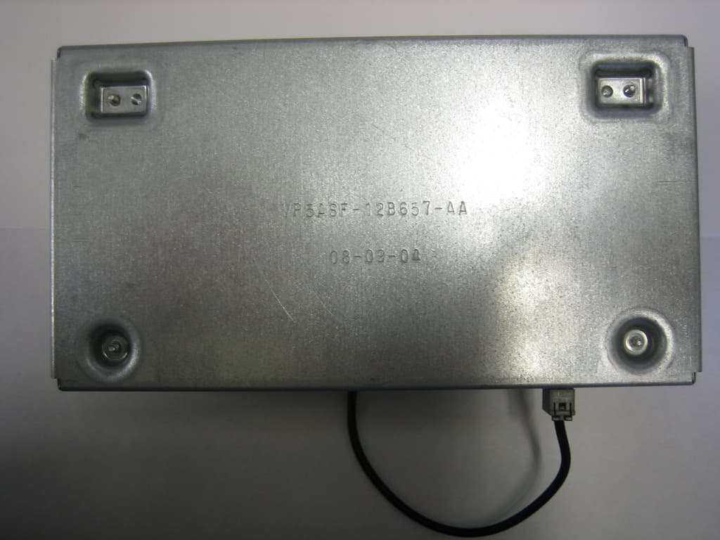
Click to zoom
Application Details
- Equipment Class
- DSS - Part 15 Spread Spectrum Transmitter
- Date of Grant
- Jun 01, 2005
- Application Purpose
- Original Equipment
- Date of Application
- Jun 01, 2005
- Equipment Note
- VMVL2.1a
- Frequency Range
- 2402.00000000 - 2480.00000000
- Company
- Visteon Corporation
- Country
- United States
Documents & Files
Document Text
Text extracted from the exhibit documents filed with the FCC. Open a document above to read the original.
Users Manual
**VISTEON CONFIDENTIAL** Page 1 of 1 See the possibilities Florencio Ceballos Product Design Engineer Infotainment Subsystems May 16, 2005 Visteon Corporation Visteon Technical Center 17000 Rotunda Drive Suite C130-65 Dearborn, MI 48120, USA Tel: 313.755.0380 Fax: 313.755.3577 Email: [email protected] Declaration for FCC warning statement Visteon Corporation, USA hereby declares that for the product: Visteon Part Number: VP5ASF-14B409-B with the FCC ID: NT806NBTHFA the following statement will be printed into the owners manual: This device complies with part 15 of the FCC Rules. Operation is subject to the following two conditions: (1) This device may not cause harmful interference, and (2) this device must accept any interference received, including interference that may cause undesired operation. Changes or modifications not expressly approved by the party responsible for compliance could void the user's authority to operate the equipment. Sincerely, Florencio Ceballos End of Document
Users Manual
VMVL2.1a Hands-Free Operating Instructions for Visteon MACH Voice Link Bluetooth Subsystem version 2.1a Version: March 15 2005 VMVL2.1a Operating Instructions Visteon Confidential Page 2 of 8 Table of Contents 1. SUT Setup ...................................................................................................3 1.1. General SUT Description................................................................................3 1.2. Test Setup...................................................................................................3 1.2.1. Setup : Connection ..................................................................................... 3 2. VMVL2.1a (HF) Functions ..............................................................................5 2.1. Pairing ........................................................................................................5 2.2. Initiate Outgoing Call from HF ........................................................................6 2.3. Initiate Outgoing Call from AG .......................................................................7 2.4. Terminate Call .............................................................................................7 2.5. Accept Incoming call .....................................................................................7 2.6. Reject an incoming call .................................................................................7 2.7. Transfer Call from HF to AG ...........................................................................7 2.8. Transfer Call from AG to HF ...........................................................................7 2.9. Call Waiting .................................................................................................8 VMVL2.1a Operating Instructions Visteon Confidential Page 3 of 8 1. SUT Setup 1.1. General SUT Description Product Name: Visteon MACH Voice Link Bluetooth Subsystem version 2.1a Product ID: VMVL2.1a 1.2. Test Setup 1.2.1. Setup : Connection Test Setup consists of the VMVL2.1a (HF), Bluetooth antenna, load board, microphone and two powered speakers. Load board includes battery switch, ignition switch, Push-To-Talk (PTT) button and End button. VMVL2.1a connects to the load board’s 32way pin connector. Microphone is connected to the load board. Microphone’s green wire is connected to MIC_PWR, red wire to MIC IN+ and white wire to MIC IN-. Speaker’s audio jack is connected to the load board’s AUDOUT connector. System is powered by a 12V DC supply. System may be initialized by flipping BATTERY switch to the ON position followed by flipping the RUN/ACC switch to the ON position. AG device communicates to the VMVL2.1a via the Bluetooth antenna allowing audio to channel through speakers. Bi-directional audio communication is possible by using the attached microphone. Calls can be initiated and transferred through the use of the PTT. Call may be terminated and rejected via the End button. Figure 1: Setup Diagram VMVL2.1a [HF] Load Board Batt Gnd Bluetooth Antenna Mic In Audio Out Run/Acc PTT (button) 12VDC J1850 End (button) Powered Speakers Mic Pwr Audio Out Mic In Mic Pwr Gnd Microphone VMVL2.1a Operating Instructions Visteon Confidential Page 4 of 8 Figure 2: Setup Photo 1) VMVL2.1a (HF) 2) Bluetooth Antenna 3) Load Board 4) Audio Out Jack 5) Speakers 6) Battery Switch 7) Run/Acc Switch 8) End Button 9) PTT Button 10) Microphone 11) Microphone Connection 6 5 2 1 4 9 3 10 7 8 11 VMVL2.1a Operating Instructions Visteon Confidential Page 5 of 8 2. VMVL2.1a (HF) Functions 2.1. Pairing Once system is initialized as described in Section 1.2.1 user may pair an AG device to the HF by following the steps below. 1. Press PTT button and wait for audible beep 2. Release PTT button after audible beep 3. Every voice recognition session begins at the HF’s Main Menu 4. If no AGs are paired, HF will say “No phone paired. Would you like to pair one now?” 5. Say “Yes”. Go to step 7 6. If an AG is already paired to HF, please say “Setup, Pair Phone” after you press PTT and hear audible beep. 7. HF says “Please initiate pairing from your handset. For further instructions refer to your phone’s user manual.” 8. Initiate pairing from AG 9. HF says “Please say the name for the phone” 10. Say name that you wish to give the AG 11. HF says “Please assign a priority level to <Phonename> by saying [1], [2], [3], [4] or [5]” Up to five AGs may be paired to the HF, but only one will have an active Bluetooth connection. 12. Say one number between 1 and 5 13. HF says “<Phonename> saved with a priority of <priority>” 14. HF says “Would you like to set a custom ring tone for <phonename>” 15. Say “No”. This will speed up the pairing process 16. HF says “No. The default ring tone has been assigned” 17. HF exits voice recognition session with ending beep 18. At this point the AG has completed pairing procedures with the HF. A Bluetooth link between the HF and AG is established within 3-5 seconds after pairing procedures are completed 19. HF is now ready to make outgoing handsfree calls or receive handsfree calls Note: Voice recognition session may be terminated at any time by pressing and releasing either PTT or End button or by saying “Cancel” VMVL2.1a Operating Instructions Visteon Confidential Page 6 of 8 2.2. Initiate Outgoing Call from HF In order to initiate an outgoing call. An AG needs to be paired to the HF and have an active Bluetooth link. Follow the steps below in order to place a call in handsfree mode 1. Press PTT button and wait for audible beep 2. Release PTT button after audible beep 3. Every voice recognition session begins at the HF’s Main Menu 4. Say “Dial <continuous digit or single digits>” 5. HF says “<last digit bundle recognized> Continue entering digits, or say dial or correction” 6. User may continue entering digits via voice or say “Dial” to make handsfree call with the current number provided to the HF, or say “Correction” to correct the last set of di…
Text truncated - open the document above for the full version.
Cover Letter(s)
**VISTEON CONFIDENTIAL** Page 1 of 1 See the possibilities Florencio Ceballos Product Design Engineer Infotainment Subsystems May 16, 2005 Visteon Corporation Visteon Technical Center 17000 Rotunda Drive Suite C130-65 Dearborn, MI 48120, USA Tel: 313.755.0380 Fax: 313.755.3577 Email: [email protected] May 16, 2005 Federal Communications Commission Authorization and Evaluation Division 7435 Oakland Mills Road Columbia, Maryland 21046 To whom it may concern, We, Visteon Corporation, USA, hereby authorize Northwest EMC, Inc., to act on our behalf, as our agent, in the following matters related to the FCC and IC approval of our products: report submittal, related correspondence, the signing of all documents relating to these matters, and any other lawful activity necessary to obtain such certification. Any act carried out by Northwest EMC, Inc. within the scope of this authorization shall have the same affect as our own. This authorization shall expire 12 months from original date. Sincerely, Florencio Ceballos Product Design Engineer
Cover Letter(s)
Northwest EMC TCB Compliance Opinion Rev. 9/15/03 7lay0038 Information about the Applicant Company Name Visteon Corporation Grantee Ron Schuchard Address 17000 Rotunda Drive City, State, Zip Dearborn, MI 48121 Job Number 7lay0038 Model VMVL2.1a FCC ID NT806NBTHFA Agent Northwest EMC, Inc. Approval Type Original Equipment Class DTS Digital Transmission System Rule Part Bluetooth Overview This application is for certification of Visteon’s transmitter, FCC ID: NT806NBTHFA. It is a Bluetooth enabled device designed to provide hands free operation of a Bluetooth enabled cellular phone in a motor vehicle. The radio utilizes an antenna with a non-standard connector (Hirose GT16C-1S-HU). This configuration satisfies the requirements of 47 CFR 15.203. Recommendation All items have been resolved and completed to my satisfaction; therefore I recommend this application for approval. Signature 5/31/2005 Dave Tolman, TCB Committee Northwest EMC TCB Compliance Opinion Rev. 9/15/03 7lay0038 Findings Opinions Specification Requirements Description 47 Cfr 2.1033(b)(3) Installation guide, operating instructions,user manual Opinion The device meets the requirements of the rule. Discussion The client has provided the necessary exhibit. Reference User Manual.pdf Specification Requirements Description 47 Cfr 2.1033(b)(4) Operational description Opinion The device meets the requirements of the rule. Discussion The client has provided the necessary exhibit. Reference Operational Description.pdf Specification Requirements Description 47 Cfr 2.1033(b)(5) Frequency block diagram Opinion The device meets the requirements of the rule. Discussion The client has provided the necessary exhibit. Reference Frequency Block Diagram.pdf Specification Requirements Description 47 Cfr 2.1033(b)(5) Schematic diagram Opinion The device meets the requirements of the rule. Discussion The client has provided the necessary exhibit. Reference Schematics.pdf Specification Requirements Description 47 cfr 2.1033(b)(6) Test Report Opinion The device meets the requirements of the rule. Discussion The client has provided the necessary exhibit. Reference Report-7lay0038.pdf Specification Requirements Description 47 Cfr 2.1033(b)(6) Conversions showing how the test results were achieved Opinion The device meets the requirements of the rule. Discussion The client has provided the necessary exhibit. Reference Report-7lay0038.pdf Northwest EMC TCB Compliance Opinion Rev. 9/15/03 7lay0038 Specification Requirements Description 47 Cfr 2.1033(b)(7) Internal and external photos Opinion The device meets the requirements of the rule. Discussion The client has provided the necessary exhibit. Reference Internal Photos.pdf, External Photos.pdf Specification Requirements Description 47 Cfr 1.1307(b),2.1091,2.1093 RF Exposure Hazzard Opinion The device meets the requirements of the rule. Discussion The client has provided the necessary exhibit. Reference RF Exposure.pdf Specification Requirements Description 47 Cfr 15.19 Labeling Opinion The device meets the requirements of the rule. Discussion The client has provided the necessary exhibit. Reference User Manual.pdf, FCC ID Label.pdf,Users Manual FCC Statement and Warning.pdf Specification Requirements Description 47 Cfr 15.21 Information for user Opinion The device meets the requirements of the rule. Discussion The client has provided the necessary exhibit. Reference User Manual.pdf Specification Requirements Description 47 Cfr 15.27 Special accessories Opinion The device meets the requirements of the rule. Discussion The client has provided the necessary exhibit. Reference Report-7lay0038.pdf Specification Requirements Description 47 Cfr 15.33 Frequency range of tests Opinion The device meets the requirements of the rule. Discussion The client has provided the necessary exhibit. Reference Report-7lay0038.pdf Specification Requirements Description 47 Cfr 15.35 Measurement detectors Opinion The device meets the requirements of the rule. Discussion The client has provided the necessary exhibit. Reference Report-7lay0038.pdf Northwest EMC TCB Compliance Opinion Rev. 9/15/03 7lay0038 Specification Requirements Description ANSI C63.4 EUT Ports All EUT ports populated, emissions maximized, Antenna height adjusted Opinion The device meets the requirements of the rule. Discussion The client has provided the necessary exhibit. Reference Report-7lay0038.pdf Specification Requirements Description 47 Cfr 15.203 Antenna Requirements Opinion The device meets the requirements of the rule. Discussion The client has provided the necessary exhibit. Reference Antenna Info.pdf Specification Requirements Description 47 Cfr 15.209 Spurious Emissions Opinion The device meets the requirements of the rule. Discussion The client has provided the necessary exhibit. Reference Report-7lay0038.pdf Specification Requirements Description BLUETOOTH FCC Procedure 2-15-02 Bluetooth Common Items Opinion The device meets the requirements of the rule. Discussion The client has provided the necessary exhibit. Reference Report-7lay0038.pdf Specification Requirements Description 47 cfr 15.247 Operation within specified bands Opinion The device meets the requirements of the rule. Discussion The client has provided the necessary exhibit. Reference Report-7lay0038.pdf Specification Requirements Description 47 Cfr 15.247(a) Occupied Bandwidth Opinion The device meets the requirements of the rule. Discussion The client has provided the necessary exhibit. Reference Report-7lay0038.pdf Specification Requirements Description 47 Cfr 15.247(b) Output Power Opinion The device meets the requirements of the rule. Discussion The client has provided the necessary exhibit. Reference Report-7lay0038.pdf Northwest EMC TCB Compliance Opinion Rev. 9/15/03 7lay0038 Specification Requirements Description 47 Cfr 15.247(d) Band Edge Compliance Opinion The device meets the requirements of the rule. Discussion The client has provided the necessary exhibit. Reference Repo…
Text truncated - open the document above for the full version.
Cover Letter(s)
NORTHWEST EMC, INC. 22975 NW Evergreen Parkway, Suite 400 Hillsboro, OR 97124 May 25, 2005 Dear Application Examiner: On behalf of Visteon Corporation, Northwest EMC, Inc. is submitting this application for the certification of Visteon’s transmitter, FCC ID: NT806NBTHFA. It is a Bluetooth enabled device designed to provide hands free operation of a Bluetooth enabled cellular phone in a motor vehicle. The radio utilizes an antenna with a non-standard connector (Hirose GT16C-1S-HU). This configuration satisfies the requirements of 47 CFR 15.203. The technical reports and exhibits demonstrate compliance with FCC rules 47 CFR 15.247 as a frequency hopping transmitter. Your efforts in reviewing this application are greatly appreciated. Best regards, Northwest EMC, Inc.
Cover Letter(s)
**VISTEON CONFIDENTIAL** Page 1 of 1 See the possibilities Florencio Ceballos Product Design Engineer Infotainment Subsystems May 16, 2005 Visteon Corporation Visteon Technical Center 17000 Rotunda Drive Suite C130-65 Dearborn, MI 48120, USA Tel: 313.755.0380 Fax: 313.755.3577 Email: [email protected] May 16, 2005 Federal Communications Commission Authorization and Evaluation Division 7435 Oakland Mills Road Columbia, Maryland 21046 To whom it may concern, Visteon Corporation, hereby respectfully request that under the provision of 47 CFR 0.459, the documents listed below and attached with this application for certification be provided with confidential status. • 7_Schematics.pdf • 12_Operational Description_A.pdf • 8_Frequency Block Diagram_A.pdf Any exhibit / information for which we have requested confidentiality, but which may not be accorded such treatment by the FCC, should be returned to us. The documents listed above contain trade secrets that are treated as confidential by us. Substantial competitive harm to us could result should they be made available to the public. Sincerely, Florencio Ceballos Product Design Engineer
Operational Description
Page 1 of 1 See the possibilities Florencio Ceballos Product Design Engineer Infotainment Subsystems May 23, 2005 Visteon Corporation Visteon Technical Center 17000 Rotunda Drive Suite C130-65 Dearborn, MI 48120, USA Tel: 313.755.0380 Fax: 313.755.3577 Email: [email protected] Visteon Bluetooth Antenna Information Antenna Type: RHCP Rectangular Patch Part Number: VP5ASF-19C037-AA Max Gain: 4dBic FC End of Document
RF Exposure Info
Compliance with 47 CFR 15.247(i) “Systems operating under the provisions of this section shall be operated in a manner that ensures that the public is not exposed to radio frequency energy levels in excess of the Commission's guidelines. See § 1.1307(b)(1) of this chapter.” The EUT is a Bluetooth enabled device designed to provide hands free operation of a Bluetooth enabled cellular phone in a motor vehicle. The EUT will only be used with a separation distance of 20 centimeters or greater between the antenna and the body of the user or nearby persons and can therefore be considered a mobile transmitter per 47 CFR 2.1091(b). Since the transmit frequency is greater than 1.5 GHz, and the output power is less than 3.0 W ERP, the EUT is categorically excluded from routine environmental evaluation per 47 CFR 2.1091(c). The MPE estimates are as follows: Table 1 in 47 CFR 1.1310 defines the maximum permissible exposure (MPE) for the general population as 1 mW/cm 2 . The exposure level at a 20 cm distance from the EUT’s transmitting antenna is calculated using the general equation: S = (PG)/4πR 2 Where: S = power density (mW/cm 2 ) P = power input to the antenna (mW) G = numeric power gain relative to an isotropic radiator R = distance to the center of the radiation of the antenna (20 cm = limit for MPE estimates) PG = EIRP Solving for S, the maximum power density 20 cm from the transmitting antenna is summarized in the following table: The power density does not exceed 1 mW/cm 2 at 20 cm; therefore, the exposure condition is compliant with FCC rules. The applicant’s radio, FCC ID: NT806NBTHFA, is compliant with the requirements of 15.247(i). MPE Estimate Antenna Type Antenna Manufactur er Antenna Part No. Transmit Frequency Max Peak Conducted Output Power Antenna Gain Minimum Antenna Cable Loss Power Density @ 20 cm General Population Exposure Limit from 1.1310 (MHz)(mW)(dBi)(dB) (mW/cm 2 )(mW/cm 2 ) RHCP Rectangular PatchVisteon VP5ASF-19C037-AA24001.9400.0011 FCC ID: NT806NBTHFA
Test Report
Visteon MACH Voice Link Bluetooth Subsystem Version 2.1a (VMVL2.1a) May 23, 2005 Report No. 7LAY0038 Report Prepared By: www.nwemc.com 1-888-EMI-CERT © 2004 Northwest EMC, Inc 22975 NW Evergreen Parkway Suite 400 Hillsboro, Oregon 97124 Certificate of Test Issue Date: May 23, 2005 Visteon MACH Voice Link Bluetooth Subsystem version 2.1a (VMVL2.1a) Emissions Specification Test Method Pass Fail FCC 15.247(a) Occupied Bandwidth:2004 ANSI C63.4:2003 FCC 15.247(b) Output Power:2004 ANSI C63.4:2003 FCC 15.247(d) Band Edge Compliance:2004 ANSI C63.4:2003 FCC 15.247(d) Spurious Conducted Emissions:2004 ANSI C63.4:2003 FCC 15.247(d) Spurious Radiated Emissions:2004 ANSI C63.4:2003 Modifications made to the product See the Modifications section of this report Test Facility The measurement facility used to collect the data is located at: Northwest EMC, Inc. 41 Tesla Irvine, CA 92618 Phone: (503) 844-4066 Fax: 844-3826 This site has been fully described in a report filed with and accepted by the FCC (Federal Communications Commission) and Industry Canada. Approved By: Dean Ghizzone, President This report must not be used to claim product certification, approval, or endorsement by NVLAP, NIST, or any agency of the federal government of the United States of America. Product compliance is the responsibility of the client, therefore the tests and equipment modes of operation represented in this report were agreed upon by the client, prior to testing. This Report may only be duplicated in its entirety. The results of this test pertain only to the sample(s) tested, the specific description is noted in each of the individual sections of the test report supporting this certificate of test. Northwest EMC Revision History Revision 05/05/03 Revision Number Description Date Page Number 00 None Northwest EMC Accreditations and Authorizations Revision 03/18/05 FCC: Accredited by NVLAP for performance of FCC radio, digital, and ISM device testing. Our Open Area Test Sites, certification chambers, and conducted measurement facilities have been fully described in reports filed with the FCC and accepted by the FCC in letters maintained in our files. Northwest EMC has been accredited by ANSI to ISO / IEC Guide 65 as a product certifier. We have been designated by the FCC as a Telecommunications Certification Body (TCB). This allows Northwest EMC to certify transmitters to FCC specifications in accordance with 47 CFR 2.960 and 2.962. NVLAP: Northwest EMC, Inc. is recognized under the United States Department of Commerce, National Institute of Standards and Technology, and National Voluntary Laboratory Accreditation Program for satisfactory compliance with the requirements of ISO/IEC 17025 for Testing Laboratories. The NVLAP accreditation encompasses Electromagnetic Compatibility Testing in accordance with the European Union EMC Directive 89/336/EEC, ANSI C63.4, MIL- STD 461E, DO-160D and SAE J1113. Additionally, Northwest EMC is accredited by NVLAP to perform radio testing in accordance with the European Union R&TTE Directive 1999/5/EEC, the requirements of FCC, and the RSS radio standards for Industry Canada. 200629-0 200630-0 200676-0 Industry Canada: Accredited by NVLAP for performance of Industry Canada RSS and ICES testing. Our Open Area Test Sites and certification chambers comply with RSS 212, Issue 1 (Provisional) and have been filed with Industry Canada and accepted. Northwest EMC has been accredited by ANSI to ISO / IEC Guide 65 as a product certifier. We have been designated by NIST and recognized by Industry Canada as a Certification Body (CB) per the APEC Mutual Recognition Arrangement (MRA). This allows Northwest EMC to certify transmitters to Industry Canada technical requirements. CAB: Designated by NIST and validated by the European Commission as a Conformity Assessment Body (CAB) to conduct tests and approve products to the EMC directive and transmitters to the R&TTE directive, as described in the U.S. - EU Mutual Recognition Agreement. TÜV Product Service: Included in TUV Product Service Group's Listing of Recognized Laboratories. It qualifies in connection with the TUV Certification after Recognition of Agent's Testing Program for the product categories and/or standards shown in TUV's current Listing of CARAT Laboratories, available from TUV. A certificate was issued to represent that this laboratory continues to meet TUV's CARAT Program requirements. Certificate No. USA0401C. TÜV Rheinland: Authorized to carryout EMC tests by order and under supervision of TÜV Rheinland. This authorization is based on "Conditions for EMC-Subcontractors" of November 1992. Northwest EMC Accreditations and Authorizations Revision 03/18/05 NEMKO: Assessed and accredited by NEMKO (Norwegian testing and certification body) for European emissions and immunity testing. As a result of NEMKO's laboratory assessment, they will accept test results from Northwest EMC, Inc. for product certification (Authorization No. ELA 119). Technology International: Assessed in accordance with ISO Guide 25 defining the general international requirements for the competence of calibration and testing laboratories and with ITI assessment criteria LACO196. Based upon that assessment, Interference Technology International, Ltd., has granted approval for specifications implementing the EU Directive on EMC (89/336/EEC and amendments). The scope of the approval was provided on a Schedule of Assessment supplied with the certificate and is available upon request. Australia/New Zealand: The National Association of Testing Authorities (NATA), Australia has been appointed by the ACA as an accreditation body to accredit test laboratories and competent bodies for EMC standards. Accredited test reports or assessments by competent bodies must carry the NATA logo. Test reports made by an overseas laboratory that has been accredited for the relevant standards by an overseas accreditation body that has a Mutual Recognition Agreement (MRA) with NATA are also acc…
Text truncated - open the document above for the full version.
Test Report
Northwest EMC Spurious Conducted Emissions Revision 10/1/03 Justification The individuals and/or the organization requesting the test provided the modes, configurations and settings available to evaluate. While scanning the radiated emissions, all of the EUT parameters listed below were investigated. This includes, but may not be limited to, antennas, tuned transmit frequency ranges, operating modes, and data rates. Channels in Specified Band Investigated: Low Mid High Operating Modes Investigated: No Hop Data Rates Investigated: Maximum Output Power Setting(s) Investigated: Maximum Power Input Settings Investigated: 12 VDC. Software\Firmware Applied During Test Operating system Unknown Version Unknown Exercise software VACM Utility Software Version 3.0.8 Description The system was tested using special firmware developed to test all functions of the device during the test. The firmware put the radio into a no-hop mode with a modulated carrier. Transmit channels were selectable between the lowest, a middle, and the highest channels in the operating band. EUT and Peripherals in Test Setup Boundary Description Manufacturer Model/Part Number Serial Number SCP Network Analysis Tool Ford N/A 015674 Bluetooth Hands Free Unit Visteon VMVL2.1a MV42001173 Bluetooth Hands Free Unit Visteon VMVL2.1a MV42001005 Control Box w/harness Nissan MVL 2005 N/A 10Amp/13.8VDC Power Supply RadioShack TM CAT. No. 22-506 806977 DC Power Supply Hewlett Packard 6574A US36340150 Northwest EMC Spurious Conducted Emissions Revision 10/1/03 Cables Cable Type Shield Length (m) Ferrite Connection 1 Connection 2 DC Leads No 3.2 No SCP Network Analysis Tool DC Power Supply DC Leads No 0.6 No Control Box w/harness 10Amp/13.8VDC Power Supply AC Power No 1.8 No 10Amp/13.8VDC Power Supply AC Mains AC Power No 2.0 No DC Power Supply AC Mains Serial No 1.4 No SCP Network Analysis Tool Control Box w/harness DC Leads No 3.6 No Control Box w/harness Bluetooth Hands Free Unit Control No 3.6 No Control Box w/harness Bluetooth Hands Free Unit SMA No 1.2 No Spectrum Analyzer RF adapter cable RF adapter cable No 0.2 No SMA cable Bluetooth Hands Free Unit PA = Cable is permanently attached to the device. Shielding and/or presence of ferrite may be unknown. Measurement Equipment Description Manufacturer Model Identifier Last Cal Interval Spectrum Analyzer Hewlett Packard 8593E AAP 12/07/2004 13 mo Spectrum Analyzer Hewlett Packard 8593E AAA 12/06/2004 13 mo Test Description Requirement: Per 47 CFR 15.247(d), in any 100 kHz bandwidth outside the authorized band, the maximum level of radio frequency power must be at least 20dB down from the highest emission level within the authorized band. The measurement is made with the spectrum analyzer’s resolution bandwidth set to 100 kHz, and the video bandwidth set to greater than or equal to the resolution bandwidth. Configuration: The spurious RF conducted emissions were measured with the EUT set to low, medium, and high transmit frequencies. The measurements were made using a direct connection between the RF output of the EUT and the spectrum analyzer. The EUT was transmitting at its maximum data rate in a no hop mode. For each transmit frequency, the spectrum was scanned throughout the specified frequency. Completed by: NORTHWEST2 EMC Rev BETA 01/30/01 EUT: VMVL2.1aWork Order: Serial Number: MV42001173Date: Customer: Visteon Temperature: 70 °F Attendees: NoneTested by: Jonathan PengHumidity: 51% RH Customer Ref. No.: N/APower: 12VDCJob Site: OC11 TEST SPECIFICATIONS Specification: 47 CFR 15.247(d)Year: 2004Method: DA 00-705, ANSI C63.4Year: 2003 SAMPLE CALCULATIONS COMMENTS EUT OPERATING MODES DEVIATIONS FROM TEST STANDARD REQUIREMENTS RESULTS Pass SIGNATURE Tested By: DESCRIPTION OF TEST Maximum level of any spurious emission outside of the authorized band is 20 dB down from the fundamental EMISSIONS DATA SHEET Antenna Conducted Spurious Emissions - Low Channel 0MHz-2.9GHz None Modulated at maximum data rate 7LAY0030 03/18/05 NORTHWEST2 EMC Rev BETA 01/30/01 EUT: VMVL2.1aWork Order: Serial Number: MV42001173Date: Customer: Visteon Temperature: 70 °F Attendees: NoneTested by: Jonathan PengHumidity: 51% RH Customer Ref. No.: N/APower: 12VDCJob Site: OC11 TEST SPECIFICATIONS Specification: 47 CFR 15.247(d)Year: 2004Method: DA 00-705, ANSI C63.4Year: 2003 SAMPLE CALCULATIONS COMMENTS EUT OPERATING MODES DEVIATIONS FROM TEST STANDARD REQUIREMENTS RESULTS Pass SIGNATURE Tested By: DESCRIPTION OF TEST Maximum level of any spurious emission outside of the authorized band is 20 dB down from the fundamental EMISSIONS DATA SHEET Antenna Conducted Spurious Emissions - Low Channel 2.9GHz-6.0GHz None Modulated at maximum data rate 7LAY0030 03/18/05 NORTHWEST2 EMC Rev BETA 01/30/01 EUT: VMVL2.1aWork Order: Serial Number: MV42001173Date: Customer: Visteon Temperature: 70 °F Attendees: NoneTested by: Jonathan PengHumidity: 51% RH Customer Ref. No.: N/APower: 12VDCJob Site: OC11 TEST SPECIFICATIONS Specification: 47 CFR 15.247(d)Year: 2004Method: DA 00-705, ANSI C63.4Year: 2003 SAMPLE CALCULATIONS COMMENTS EUT OPERATING MODES DEVIATIONS FROM TEST STANDARD REQUIREMENTS RESULTS Pass SIGNATURE Tested By: DESCRIPTION OF TEST Maximum level of any spurious emission outside of the authorized band is 20 dB down from the fundamental EMISSIONS DATA SHEET Antenna Conducted Spurious Emissions - Low Channel 6GHz-12.8GHz None Modulated at maximum data rate 7LAY0030 03/18/05 NORTHWEST2 EMC Rev BETA 01/30/01 EUT: VMVL2.1aWork Order: Serial Number: MV42001173Date: Customer: Visteon Temperature: 70 °F Attendees: NoneTested by…
Text truncated - open the document above for the full version.
Contact Information
Applicant
Terry SanSouci(Product Assurance Test Engineer)
Test Firm
Northwest EMC, Inc.Greg Kiemel
Technical Specifications
| # | Rule Parts | Frequency Range | Power Output |
|---|---|---|---|
| 1 | 15C | 2.40 GHz - 2.48 GHz | 1.90 mW |
Other Applications from Visteon Corporation
NT8-BPCMFXE
Feb 20, 2026Battery Pack Control Module (BPCM)
Equipment Class
JAB - Part 15 Class B Digital DeviceNT8-BPCMSW
Dec 02, 2024Battery Pack Control Module (BPCM)
Equipment Class
DTS - Digital Transmission System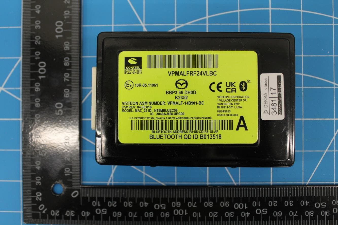
NT8-MAZ22HFT
Feb 15, 2024Bluetooth Telematics Device
Equipment Class
DSS - Part 15 Spread Spectrum Transmitter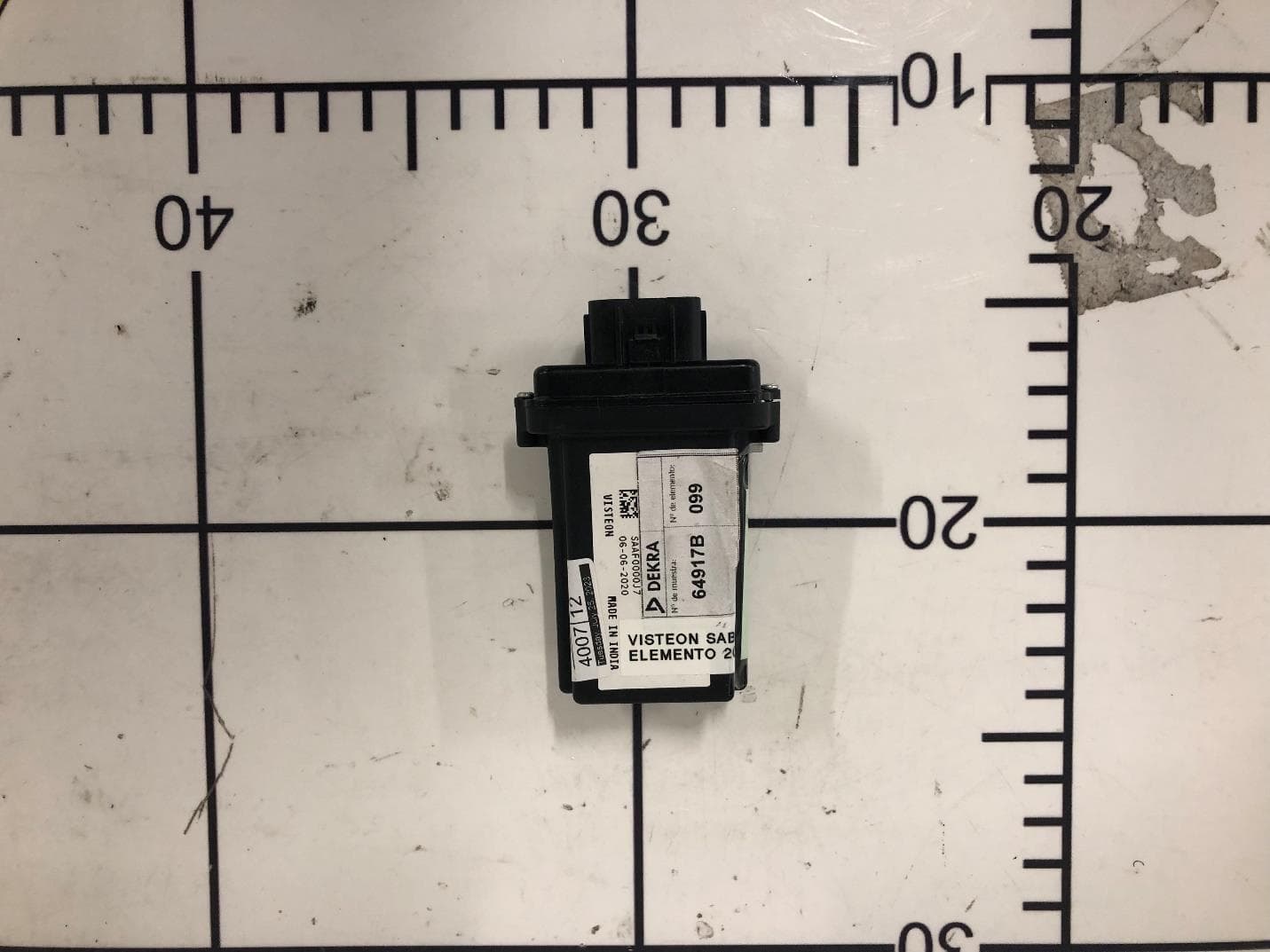
NT8-SAB01
Nov 01, 2023BT Unit
Equipment Class
DSS - Part 15 Spread Spectrum TransmitterNT8-SLA12
Jun 22, 2023Sense Line Assembly (SLA)
Equipment Class
JAB - Part 15 Class B Digital Device